EP1993115B1 - Steuervorrichtung zur Kontaktherstellung oder -unterbrechung zwischen zwei Teilen und mit dieser Vorrichtung ausgestattetes elektrisches Gerät - Google Patents
Steuervorrichtung zur Kontaktherstellung oder -unterbrechung zwischen zwei Teilen und mit dieser Vorrichtung ausgestattetes elektrisches Gerät Download PDFInfo
- Publication number
- EP1993115B1 EP1993115B1 EP20080354019 EP08354019A EP1993115B1 EP 1993115 B1 EP1993115 B1 EP 1993115B1 EP 20080354019 EP20080354019 EP 20080354019 EP 08354019 A EP08354019 A EP 08354019A EP 1993115 B1 EP1993115 B1 EP 1993115B1
- Authority
- EP
- European Patent Office
- Prior art keywords
- spring
- operating shaft
- contact
- parts
- shaft
- Prior art date
- Legal status (The legal status is an assumption and is not a legal conclusion. Google has not performed a legal analysis and makes no representation as to the accuracy of the status listed.)
- Not-in-force
Links
Images


Classifications
-
- H—ELECTRICITY
- H01—ELECTRIC ELEMENTS
- H01H—ELECTRIC SWITCHES; RELAYS; SELECTORS; EMERGENCY PROTECTIVE DEVICES
- H01H3/00—Mechanisms for operating contacts
- H01H3/22—Power arrangements internal to the switch for operating the driving mechanism
- H01H3/30—Power arrangements internal to the switch for operating the driving mechanism using spring motor
- H01H3/3047—Power arrangements internal to the switch for operating the driving mechanism using spring motor adapted for operation of a three-position switch, e.g. on-off-earth
-
- H—ELECTRICITY
- H01—ELECTRIC ELEMENTS
- H01H—ELECTRIC SWITCHES; RELAYS; SELECTORS; EMERGENCY PROTECTIVE DEVICES
- H01H1/00—Contacts
- H01H1/50—Means for increasing contact pressure, preventing vibration of contacts, holding contacts together after engagement, or biasing contacts to the open position
-
- H—ELECTRICITY
- H01—ELECTRIC ELEMENTS
- H01H—ELECTRIC SWITCHES; RELAYS; SELECTORS; EMERGENCY PROTECTIVE DEVICES
- H01H5/00—Snap-action arrangements, i.e. in which during a single opening operation or a single closing operation energy is first stored and then released to produce or assist the contact movement
- H01H5/04—Energy stored by deformation of elastic members
- H01H5/06—Energy stored by deformation of elastic members by compression or extension of coil springs
Definitions
- the present invention relates to a device for controlling the placing in contact or out of contact of two parts, at least one of which is movable relative to the other, comprising an operating shaft connected in an articulated manner relative to a frame, said shaft being adapted to be rotated between a first position corresponding to a position of contact of the two parts and a second position corresponding to a so-called distance position of the two parts, a compression spring adapted to be compressed by said shaft and to act during its decompression on the moving part so as to bring said movable part in a position of contact with the fixed part and means for separating the two parts able to bring the two aforementioned parts in the aforementioned removal position, said spring cooperating by one said one of its ends, with the operating shaft by its opposite end said second, with the piece mo bile.
- This device ensuring the control of a sectioning or a grounding.
- This device comprises an operating shaft rotatably mounted relative to a frame and hingedly connected to one end of a spring system whose opposite end is hingedly connected to an output shaft connected in an articulated manner. auditing and controlling the movement of the moving part.
- the ground is effected by a rotation of the actuating shaft causing compression of the spring until a dead point.
- the operating shaft continues its rotation by a few degrees by releasing a hooking roller via a connecting rod.
- the roller thus released, the output shaft rotates under the action of the spring, and causes the cutting of the contacts.
- the latter drives the latching roller to bring it into contact with a stop.
- the opening to the ground is performed by the reverse rotation of the operating shaft.
- the connecting rod then drives the roller, which in turn drives the output shaft.
- the present invention relates to a device for controlling the contacting and the putting out of contact of two parts relative to each other, of simple design, which allows the two parts to come into contact with a speed independent of each other. the operator and to ensure a significant contact pressure.
- the subject of the present invention is a device for controlling the placing in contact or out of contact of two parts of the kind mentioned above, this device being characterized in that it comprises return means for returning the exerted force by the first end of the spring during its decompression, on the moving part, so that said movable part receives two forces exerted respectively by the two ends of the spring, the resultant of the two forces corresponding to these two forces to ensure a clamping important between the two parts mentioned above.
- these return means comprise a driving rod connected in an articulated manner by one of its ends, said first, to the operating shaft, and by its opposite end said second, to the moving part.
- the maneuvering shaft comprises two ends disposed on either side of its axis of articulation to the frame, the spring is connected in an articulated manner by its so-called first end, on the one so-called second ends of the operating shaft, and its so-called second end, is hingedly connected to the moving part.
- the distance separating, on the one hand, the axis of articulation of the operating shaft from the frame, and, on the other hand, the axis of articulation of the connecting rod to the operating shaft corresponds substantially to the distance separating the axis of articulation of the shaft from the housing and the axis of articulation of the first end of the spring to said shaft.
- the operating shaft, the connecting rod and the spring are dimensioned in such a way that the evolution of the lever arms during the placing in contact of the fixed and moving parts makes it possible to compensate for the decrease in the effort the spring during its elongation, so that a constant force is applied to the movable contact.
- the aforementioned device can take three stable positions, namely a closed equilibrium position in which the parts are in contact and the spring in partially decompressed position, an open equilibrium position in which the parts are separated and the spring in a fully compressed position and a neutral position in which the parts are separated and the three axes of articulation respectively of the connecting rod on the operating shaft, the spring on the operating shaft, and the spring on the movable contact, are aligned in which position the direction of the forces transmitted by the spring is such that no torque is applied to the operating shaft and position beyond which the spring becomes motor and causes the operating shaft and the movable contact.
- the operating shaft comprises a stop adapted to cooperate with the connecting rod to limit the rotational travel of the operating shaft beyond the neutral position of the passage position, after an opening maneuver.
- the present invention also relates to an electrical protection apparatus comprising a fixed contact and a movable contact, the movable contact being controlled by a control device having the aforementioned characteristics taken alone or in combination.
- the movable contact is a ground contact.
- it is an earthing switch having a closing power.
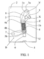
- a control device O of the contacts of an earthing switch comprises an operating shaft 1 connected in an articulated manner along an axis X to a frame 2.
- This operating shaft is also connected in an articulated manner (Y) by one of its ends, at one end 3a of the ends of a drive rod 3, and its opposite end 1b (Z), to a compression spring 4.
- This rod of drive 3 and the compression spring 4 are connected to each other in a manner articulated by their other end 3b, 4b, to a connecting axis U, this connecting axis U being connected in an articulated manner on the one hand, to a movable contact 6, and on the other hand, to a connected connecting rod 7 also articulated to the frame.
- the fixed contact 5 is rigidly connected to the frame to withstand the efforts of maintaining in the closed position the two contacts 5,6.
- This device has two stable equilibrium positions and an unstable equilibrium position.
- the first stable equilibrium position is the open position represented on the figure 1 . In this position, the driving rod 3 is in abutment on an opening stop 8 secured to the operating shaft 1.
- the second stable equilibrium position is the closed position represented on the figure 3 . In this position, the moving contact is in abutment on the fixed contact.
- the unstable equilibrium position represented on the figure 2 is that in which the three axes of articulation respectively, the Y axis of articulation of the connecting rod 3 on the shaft 1, the axis Z of articulation of the shaft 1 to the spring 4 and the axis U of articulation of the connecting rod 3 on the movable contact 6, are aligned.
- this position called the neutral passage
- the direction of the force transmitted by the spring is such that no torque is applied to the operating shaft.
- the assembly can therefore switch either to the open position or to the closed position.
- the mechanism operates autonomously under the action of the compression spring as will be explained in the following.
- the operating shaft is subjected to a torque exerted by two forces, which forces vary according to the length of the spring and according to the evolution of the lever arms D1 ', D2' ( figure 4 ).
- the first force, called F1 is exerted directly by the lower end of the spring 4b and is retransmitted to the operating shaft 1 via the driving rod 3.
- the second force named F2 is the result of the force transmitted to the actuating shaft 1 by the upper end 4a of the spring 4.
- This second force F2 is retransmitted along F3 to the movable contact 6 via the two lever arms D1 and D2.
- the resultant R of the forces applied to the moving contact is therefore about twice the force provided by the first end 4a of the spring 4.
- the value of this effort resultant R varies very little regardless of the position of the fixed contact 5 during the last two thirds of the race as illustrated in FIG. figure 5 .
- the variation of the lever arms D1 'and D2' makes it possible to compensate for the drop in the force of the spring during its elongation. The lower the F1 and F2 forces, the more the effort F3 increases.
- a control device has thus been produced according to the invention making it possible to bring the mobile contact against the fixed contact with a speed independent of the operator.
- this device ensures, thanks to the compression spring, a significant contact pressure to allow the flow of current.
- the system is maintained open position by contacting the drive rod on a workpiece forming a stop of the operating shaft under the action of the compression spring.
- the use of the force of both ends of the spring allows the use of a lower force spring (about half the contact force to obtain).
- the evolution of the lever arms during the closure of the contacts to compensate for the decrease in the spring force on the last two thirds of the race, it follows a retransmitted effort on the contacts that remains constant on a large race.
- This principle is well suited for driving contacts when significant end-of-travel forces are required (eg end-to-end contacts), see all contacts that require overtravel to compensate for wear, matting, etc. It is applicable to all electrical functions without breaking capacity, especially of the disconnector type.
- This principle can be used to simply apply a holding force (ex: clamping), clamping several parts together. It is also well suited for all earthing switch functions with breaking capacity. For other applications, it can be coupled to a shaft to transform the linear output movement into a rotational movement. It can also be associated with a cam system to adapt the efforts transmitted to specific needs. It can also be used, with the disengagement of the operating shaft and the drive rod, for all switch functions, or even circuit breakers with the attachment setting for tripping.
Landscapes
- Driving Mechanisms And Operating Circuits Of Arc-Extinguishing High-Tension Switches (AREA)
- Mechanisms For Operating Contacts (AREA)
Claims (10)
- Antriebsvorrichtung zur Zusammenführung oder Trennung von zwei Schaltstücken, von denen mindestens eines in Bezug zum anderen beweglich ausgebildet ist, welche Vorrichtung eine gelenkig mit einem Gehäuse verbundene Schaltwelle, die zwischen einer ersten, einer Kontaktstellung der beiden Schaltstücke entsprechenden Stellung sowie einer zweiten, einer so genannten Trennstellung der beiden Schaltstücke entsprechenden Stellung drehwirksam mitgeführt werden kann, eine Druckfeder, die durch die genannte Welle komprimiert werden und bei ihrer Entspannung auf das bewegliche Schaltstück einwirken kann, derart dass das genannte bewegliche Schaltstück in eine Kontaktstellung mit dem feststehenden Schaltstück verbracht wird, sowie Trennmittel zur Trennung der beiden Schaltstücke umfasst, welche die beiden genannten Schaltstücke in die genannte Trennstellung verbringen können, wobei die genannte Feder über ihr als erstes Ende bezeichnetes Ende mit der Schaltwelle und über ihr, als zweites Ende bezeichnetes gegenüber liegendes Ende mit dem beweglichen Schaltstück zusammenwirkt, dadurch gekennzeichnet, dass die Vorrichtung Umlenkmittel (1, 3) umfasst, die dazu dienen, die vom ersten Ende der Feder (4a) bei deren Entspannung auf die Schaltwelle (1) ausgeübte Kraft auf das bewegliche Schaltstück (6) umzulenken, derart dass zwei Kräfte, die von jeweils einem Ende (4a, 4b) der Feder (4) ausgeübt werden, auf das genannte bewegliche Schaltstück (6) wirken, wobei die Resultierende der diesen beiden Kräften entsprechenden Kraftvektoren FI, F2 einen hohen Kontaktdruck zwischen den beiden genannten Schaltstücken (5, 6) gewährleistet.
- Antriebsvorrichtung nach Anspruch 1, dadurch gekennzeichnet, dass die Umlenkmittel einen Übertragungshebel (3) umfassen, der über sein, als erstes Ende bezeichnetes Ende (3a) gelenkig mit der Schaltwelle (1) und über sein als zweites Ende bezeichnetes gegenüber liegendes Ende (3b) mit dem beweglichen Schaltstück (6) verbunden ist.
- Antriebsvorrichtung nach Anspruch 2, dadurch gekennzeichnet, dass die Schaltwelle (1) zwei jeweils auf einer Seite der Drehachse X der Gelenkverbindung mit dem Gehäuse angeordnete Enden (1a, 1 b) umfasst und dass die Feder (4) über ihr als erstes Ende bezeichnetes Ende (4a) gelenkig mit einem als zweites Ende bezeichneten Ende (1 b) der Schaltwelle sowie mit ihrem als zweites Ende bezeichneten Ende (4b) gelenkig mit dem beweglichen Schaltstück (6) verbunden ist.
- Antriebsvorrichtung nach Anspruch 3, dadurch gekennzeichnet, dass der Abstand zwischen der Drehachse X der Gelenkverbindung zwischen Schaltwelle (1) und Gehäuse (2) einerseits und zwischen der Drehachse Y der Gelenkverbindung zwischen Übertragungshebel (3) und Schaltwelle (1) andererseits annähernd dem Abstand zwischen der Drehachse X der Gelenkverbindung zwischen Schaltwelle (1) und Gehäuse (2) und der Drehachse Z der Gelenkverbindung zwischen dem ersten Ende (4a) der Feder (4) und der Schaltwelle (1) entspricht.
- Antriebsvorrichtung nach irgendeinem der Ansprüche 2 bis 4, dadurch gekennzeichnet, dass die Schaltwelle (1), der Übertragungshebel (3) und die Feder (4) so dimensioniert sind, dass bei der Zusammenführung des beweglichen und des feststehenden Schaltstücks (5, 6) die Abnahme der Kraft der Feder (4) bei ihrer Entspannung durch die Veränderung der Hebelarme D1' und D2' ausgeglichen werden kann, so dass das bewegliche Schaltstück (6) stets mit einer konstanten Kraft beaufschlagt wird.
- Antriebsvorrichtung nach irgendeinem der Ansprüche 3 bis 5, dadurch gekennzeichnet, dass die genannte Vorrichtung drei stabile Stellungen einnehmen kann, und zwar eine Einschalt-Gleichgewichtsstellung mit Kontaktgabe der Schaltstücke (5, 6) und teilweise entspannter Feder (4), eine Ausschalt-Gleichgewichtsstellung mit Trennung der Schaltstücke (5, 6) und vollständig komprimierter Feder (4) und eine Übertotpunktstellung, in der die Schaltstücke (5, 6) getrennt sind und die drei Drehachsen, d.h. die Drehachse Y der Gelenkverbindung zwischen Übertragungshebel (3) und Schaltwelle (1), die Drehachse Z der Gelenkverbindung zwischen Feder (4) und Schaltwelle (1) sowie die Drehachse U der Gelenkverbindung zwischen Feder (4) und beweglichem Schaltstück (6) miteinander fluchten, wobei in dieser Stellung die von der Feder (4) ausgeübten Kräfte so gerichtet sind, dass keinerlei Kraftmoment auf die Schaltwelle (1) wirkt, und die Feder (4) bei Überwindung dieser Stellung antriebswirksam wird und die Schaltwelle (1) sowie das bewegliche Schaltstück (6) verschiebt.
- Antriebsvorrichtung nach irgendeinem der Ansprüche 2 bis 6, dadurch gekennzeichnet, dass die Schaltwelle (1) einen Endanschlag (8) umfasst, der dazu dient, mit dem Übertragungshebel (3) zusammenzuwirken, um während einer Ausschalthandlung den Drehwinkel der Schaltwelle (1) nach Überwindung der Übertotpunktstellung zu begrenzen.
- Elektrisches Schutzgerät mit einem feststehenden Kontakt (5) und einem beweglichen Kontakt (6), welcher bewegliche Kontakt (6) über eine Antriebsvorrichtung D nach irgendeinem der vorhergehenden Ansprüche angetrieben wird.
- Elektrisches Schutzgerät nach Anspruch 8, dadurch gekennzeichnet, dass der bewegliche Kontakt (6) als Erdungskontakt ausgebildet ist.
- Elektrisches Schutzgerät nach Anspruch 9, dadurch gekennzeichnet, dass es sich um einen Erdungstrenner mit einem bestimmten Einschaltvermögen handelt.
Applications Claiming Priority (1)
| Application Number | Priority Date | Filing Date | Title |
|---|---|---|---|
| FR0703471A FR2916300B1 (fr) | 2007-05-15 | 2007-05-15 | Dispositif de commande de la mise en contact ou hors contact de deux pieces et appareil electrique comportant un tel dispositif |
Publications (2)
| Publication Number | Publication Date |
|---|---|
| EP1993115A1 EP1993115A1 (de) | 2008-11-19 |
| EP1993115B1 true EP1993115B1 (de) | 2012-12-12 |
Family
ID=38812064
Family Applications (1)
| Application Number | Title | Priority Date | Filing Date |
|---|---|---|---|
| EP20080354019 Not-in-force EP1993115B1 (de) | 2007-05-15 | 2008-03-13 | Steuervorrichtung zur Kontaktherstellung oder -unterbrechung zwischen zwei Teilen und mit dieser Vorrichtung ausgestattetes elektrisches Gerät |
Country Status (7)
| Country | Link |
|---|---|
| EP (1) | EP1993115B1 (de) |
| CN (1) | CN101308734B (de) |
| AU (1) | AU2008202132B2 (de) |
| BR (1) | BRPI0801341B1 (de) |
| ES (1) | ES2396742T3 (de) |
| FR (1) | FR2916300B1 (de) |
| RU (1) | RU2453943C2 (de) |
Families Citing this family (4)
| Publication number | Priority date | Publication date | Assignee | Title |
|---|---|---|---|---|
| DE102010033042A1 (de) * | 2010-08-02 | 2012-02-02 | Abb Technology Ag | Antrieb für einen Trennschalter mit C O-Schaltvermögen |
| FR3093227B1 (fr) * | 2019-02-21 | 2021-02-12 | Schneider Electric Ind Sas | Dispositif de commande de contacts d’une ampoule à vide pour appareil de connexion électrique |
| WO2020200951A1 (de) * | 2019-03-29 | 2020-10-08 | Siemens Aktiengesellschaft | Federsystem für ein antriebssystem mit kupplung, federsystem mit kupplung, antriebssystem mit kupplung und federsystem und schaltanlage mit einem solchen antriebssystem |
| CN111653440B (zh) * | 2020-06-19 | 2025-11-04 | 泰安市泰和电力设备有限公司 | 一种开关紧急跳脱装置及其使用方法 |
Family Cites Families (4)
| Publication number | Priority date | Publication date | Assignee | Title |
|---|---|---|---|---|
| DE1160928B (de) * | 1959-11-24 | 1964-01-09 | Erwin Wagner | Schalteinrichtung fuer elektrische Schalter |
| FR2500222A1 (fr) * | 1981-02-13 | 1982-08-20 | Merlin Gerin | Mecanisme de manoeuvre pour appareillage de commutation electrique a trois positions distinctes |
| FR2609839B1 (fr) * | 1987-01-21 | 1989-04-07 | Merlin Gerin | Mecanisme a accrochage de commande d'un disjoncteur a trois positions |
| RU2291512C1 (ru) * | 2005-07-11 | 2007-01-10 | Открытое акционерное общество "Энергомашкорпорация" | Пружинный привод для высоковольтного коммутационного аппарата |
-
2007
- 2007-05-15 FR FR0703471A patent/FR2916300B1/fr not_active Expired - Fee Related
-
2008
- 2008-03-13 EP EP20080354019 patent/EP1993115B1/de not_active Not-in-force
- 2008-03-13 ES ES08354019T patent/ES2396742T3/es active Active
- 2008-05-14 BR BRPI0801341-1A patent/BRPI0801341B1/pt not_active IP Right Cessation
- 2008-05-14 RU RU2008119136/07A patent/RU2453943C2/ru not_active IP Right Cessation
- 2008-05-14 AU AU2008202132A patent/AU2008202132B2/en not_active Ceased
- 2008-05-15 CN CN2008100992660A patent/CN101308734B/zh not_active Expired - Fee Related
Also Published As
| Publication number | Publication date |
|---|---|
| AU2008202132A1 (en) | 2008-12-04 |
| FR2916300A1 (fr) | 2008-11-21 |
| FR2916300B1 (fr) | 2009-07-10 |
| BRPI0801341A2 (pt) | 2009-03-31 |
| RU2453943C2 (ru) | 2012-06-20 |
| RU2008119136A (ru) | 2009-11-20 |
| CN101308734A (zh) | 2008-11-19 |
| EP1993115A1 (de) | 2008-11-19 |
| ES2396742T3 (es) | 2013-02-25 |
| CN101308734B (zh) | 2012-04-18 |
| BRPI0801341B1 (pt) | 2018-10-30 |
| AU2008202132B2 (en) | 2011-06-09 |
Similar Documents
| Publication | Publication Date | Title |
|---|---|---|
| EP2040276B1 (de) | Steuervorrichtung zum Öffnen und/oder Schließen von elektrischen Kontakten in einem Elektrogerät und mit dieser Vorrichtung ausgestattetes Elektrogerät | |
| EP0161120B1 (de) | Anordnung zur Lastunterbrechung und sichtbaren Trennung eines elektrischen Stromkreises | |
| EP2602804B1 (de) | Betätigungsvorrichtung für die Pole in einer elektrischen Mittelspannungsbetätigungseinrichtung | |
| EP1993115B1 (de) | Steuervorrichtung zur Kontaktherstellung oder -unterbrechung zwischen zwei Teilen und mit dieser Vorrichtung ausgestattetes elektrisches Gerät | |
| FR2923099A1 (fr) | Actionneur electromecanique muni d'un frein mecanique de type a ressort a spires enroule | |
| EP1331658B1 (de) | Elektrische Schaltvorrichtung mit Motorbetätigung und sein Steuerungsverfahren | |
| EP0372449B1 (de) | Betätigungsvorrichtung für Schalter | |
| EP3561832A1 (de) | Kraftübertragungsmodul | |
| EP1237169B1 (de) | Hochspannungsschalter mit Federsteuerung und Zusatzfeder für Energie-Rückgewinnung | |
| EP1706880A1 (de) | Steuerung für eine elektrische stromunterbrechereinrichtung | |
| EP2605264B1 (de) | Betätigungseinrichtung eines Hilfskontaktes in einer elektrischen Schaltvorrichtung | |
| EP2605256B1 (de) | Vorrichtung zur Steuerung der Resetvorrichtungs-Motorisierung der Kontaktschließvorrichtung in einem elektrischen Schutzgerät, und eine solche Vorrichtung enthaltendes Gerät | |
| EP2161730A1 (de) | Steuervorrichtung zum Öffnen und/oder Schließen von Kontakten in einem Elektrogerät | |
| EP1412651B1 (de) | Verbindungsvorrichtung für kupplungsmuffe | |
| EP2575150B1 (de) | Vorrichtung zur entkupplung des motorantriebs von der federspannvorrichtung des kontaktantriebs in einem schutzschalter und schutzschalter mit einer entsprechenden vorrichtung. | |
| EP3657522B1 (de) | Betätigungsmechanismus zum öffnen und schliessen einer stromunterbrechungsvorrichtung für einen elektrichen schalter | |
| EP1178506A1 (de) | Betätigungseinrichtung mit Kette und Startvorrichtung für elektrische Hochspannungsschalter | |
| FR3038447A1 (fr) | Dispositif de commutation | |
| FR2980624A1 (fr) | Appareil de protection electrique comportant un palonnier supportant un contact mobile | |
| EP1178505A1 (de) | Betätigungseinrichtung mit einer Zugkette für elektrische Hochspannungsschalter | |
| FR2857779A1 (fr) | Disjoncteur multipolaire | |
| FR3093227A1 (fr) | Dispositif de commande de contacts d’une ampoule à vide pour appareil de connexion électrique | |
| FR2551914A1 (fr) | Auxiliaire de telecommande pour enclenchement a distance d'un disjoncteur a prehenseur d'enclenchement et de declenchement | |
| EP3792949A1 (de) | Elektrische schaltvorrichtung mit trennbaren kontakten | |
| FR2812762A1 (fr) | Mecanisme de manoeuvre muni d'une manette de commande manuelle rotative, pour un appareillage electrique de coupure |
Legal Events
| Date | Code | Title | Description |
|---|---|---|---|
| PUAI | Public reference made under article 153(3) epc to a published international application that has entered the european phase |
Free format text: ORIGINAL CODE: 0009012 |
|
| AK | Designated contracting states |
Kind code of ref document: A1 Designated state(s): AT BE BG CH CY CZ DE DK EE ES FI FR GB GR HR HU IE IS IT LI LT LU LV MC MT NL NO PL PT RO SE SI SK TR |
|
| AX | Request for extension of the european patent |
Extension state: AL BA MK RS |
|
| 17P | Request for examination filed |
Effective date: 20081201 |
|
| RAP1 | Party data changed (applicant data changed or rights of an application transferred) |
Owner name: SCHNEIDER ELECTRIC INDUSTRIES SAS |
|
| AKX | Designation fees paid |
Designated state(s): AT BE BG CH CY CZ DE DK EE ES FI FR GB GR HR HU IE IS IT LI LT LU LV MC MT NL NO PL PT RO SE SI SK TR |
|
| GRAP | Despatch of communication of intention to grant a patent |
Free format text: ORIGINAL CODE: EPIDOSNIGR1 |
|
| RIN1 | Information on inventor provided before grant (corrected) |
Inventor name: PERRIN, DENIS |
|
| GRAS | Grant fee paid |
Free format text: ORIGINAL CODE: EPIDOSNIGR3 |
|
| GRAA | (expected) grant |
Free format text: ORIGINAL CODE: 0009210 |
|
| AK | Designated contracting states |
Kind code of ref document: B1 Designated state(s): AT BE BG CH CY CZ DE DK EE ES FI FR GB GR HR HU IE IS IT LI LT LU LV MC MT NL NO PL PT RO SE SI SK TR |
|
| REG | Reference to a national code |
Ref country code: GB Ref legal event code: FG4D Free format text: NOT ENGLISH |
|
| REG | Reference to a national code |
Ref country code: CH Ref legal event code: EP |
|
| REG | Reference to a national code |
Ref country code: AT Ref legal event code: REF Ref document number: 588677 Country of ref document: AT Kind code of ref document: T Effective date: 20121215 |
|
| REG | Reference to a national code |
Ref country code: IE Ref legal event code: FG4D Free format text: LANGUAGE OF EP DOCUMENT: FRENCH |
|
| REG | Reference to a national code |
Ref country code: DE Ref legal event code: R096 Ref document number: 602008020766 Country of ref document: DE Effective date: 20130207 |
|
| REG | Reference to a national code |
Ref country code: ES Ref legal event code: FG2A Ref document number: 2396742 Country of ref document: ES Kind code of ref document: T3 Effective date: 20130225 |
|
| PG25 | Lapsed in a contracting state [announced via postgrant information from national office to epo] |
Ref country code: NO Free format text: LAPSE BECAUSE OF FAILURE TO SUBMIT A TRANSLATION OF THE DESCRIPTION OR TO PAY THE FEE WITHIN THE PRESCRIBED TIME-LIMIT Effective date: 20130312 Ref country code: SE Free format text: LAPSE BECAUSE OF FAILURE TO SUBMIT A TRANSLATION OF THE DESCRIPTION OR TO PAY THE FEE WITHIN THE PRESCRIBED TIME-LIMIT Effective date: 20121212 Ref country code: LT Free format text: LAPSE BECAUSE OF FAILURE TO SUBMIT A TRANSLATION OF THE DESCRIPTION OR TO PAY THE FEE WITHIN THE PRESCRIBED TIME-LIMIT Effective date: 20121212 Ref country code: FI Free format text: LAPSE BECAUSE OF FAILURE TO SUBMIT A TRANSLATION OF THE DESCRIPTION OR TO PAY THE FEE WITHIN THE PRESCRIBED TIME-LIMIT Effective date: 20121212 |
|
| REG | Reference to a national code |
Ref country code: NL Ref legal event code: VDEP Effective date: 20121212 |
|
| REG | Reference to a national code |
Ref country code: AT Ref legal event code: MK05 Ref document number: 588677 Country of ref document: AT Kind code of ref document: T Effective date: 20121212 |
|
| REG | Reference to a national code |
Ref country code: LT Ref legal event code: MG4D |
|
| PG25 | Lapsed in a contracting state [announced via postgrant information from national office to epo] |
Ref country code: GR Free format text: LAPSE BECAUSE OF FAILURE TO SUBMIT A TRANSLATION OF THE DESCRIPTION OR TO PAY THE FEE WITHIN THE PRESCRIBED TIME-LIMIT Effective date: 20130313 Ref country code: LV Free format text: LAPSE BECAUSE OF FAILURE TO SUBMIT A TRANSLATION OF THE DESCRIPTION OR TO PAY THE FEE WITHIN THE PRESCRIBED TIME-LIMIT Effective date: 20121212 Ref country code: SI Free format text: LAPSE BECAUSE OF FAILURE TO SUBMIT A TRANSLATION OF THE DESCRIPTION OR TO PAY THE FEE WITHIN THE PRESCRIBED TIME-LIMIT Effective date: 20121212 |
|
| PG25 | Lapsed in a contracting state [announced via postgrant information from national office to epo] |
Ref country code: SK Free format text: LAPSE BECAUSE OF FAILURE TO SUBMIT A TRANSLATION OF THE DESCRIPTION OR TO PAY THE FEE WITHIN THE PRESCRIBED TIME-LIMIT Effective date: 20121212 Ref country code: BG Free format text: LAPSE BECAUSE OF FAILURE TO SUBMIT A TRANSLATION OF THE DESCRIPTION OR TO PAY THE FEE WITHIN THE PRESCRIBED TIME-LIMIT Effective date: 20130312 Ref country code: AT Free format text: LAPSE BECAUSE OF FAILURE TO SUBMIT A TRANSLATION OF THE DESCRIPTION OR TO PAY THE FEE WITHIN THE PRESCRIBED TIME-LIMIT Effective date: 20121212 Ref country code: IS Free format text: LAPSE BECAUSE OF FAILURE TO SUBMIT A TRANSLATION OF THE DESCRIPTION OR TO PAY THE FEE WITHIN THE PRESCRIBED TIME-LIMIT Effective date: 20130412 Ref country code: CY Free format text: LAPSE BECAUSE OF FAILURE TO SUBMIT A TRANSLATION OF THE DESCRIPTION OR TO PAY THE FEE WITHIN THE PRESCRIBED TIME-LIMIT Effective date: 20121212 Ref country code: CZ Free format text: LAPSE BECAUSE OF FAILURE TO SUBMIT A TRANSLATION OF THE DESCRIPTION OR TO PAY THE FEE WITHIN THE PRESCRIBED TIME-LIMIT Effective date: 20121212 Ref country code: EE Free format text: LAPSE BECAUSE OF FAILURE TO SUBMIT A TRANSLATION OF THE DESCRIPTION OR TO PAY THE FEE WITHIN THE PRESCRIBED TIME-LIMIT Effective date: 20121212 |
|
| PG25 | Lapsed in a contracting state [announced via postgrant information from national office to epo] |
Ref country code: PT Free format text: LAPSE BECAUSE OF FAILURE TO SUBMIT A TRANSLATION OF THE DESCRIPTION OR TO PAY THE FEE WITHIN THE PRESCRIBED TIME-LIMIT Effective date: 20130412 Ref country code: PL Free format text: LAPSE BECAUSE OF FAILURE TO SUBMIT A TRANSLATION OF THE DESCRIPTION OR TO PAY THE FEE WITHIN THE PRESCRIBED TIME-LIMIT Effective date: 20121212 Ref country code: RO Free format text: LAPSE BECAUSE OF FAILURE TO SUBMIT A TRANSLATION OF THE DESCRIPTION OR TO PAY THE FEE WITHIN THE PRESCRIBED TIME-LIMIT Effective date: 20121212 Ref country code: NL Free format text: LAPSE BECAUSE OF FAILURE TO SUBMIT A TRANSLATION OF THE DESCRIPTION OR TO PAY THE FEE WITHIN THE PRESCRIBED TIME-LIMIT Effective date: 20121212 |
|
| BERE | Be: lapsed |
Owner name: SCHNEIDER ELECTRIC INDUSTRIES SAS Effective date: 20130331 |
|
| PLBE | No opposition filed within time limit |
Free format text: ORIGINAL CODE: 0009261 |
|
| STAA | Information on the status of an ep patent application or granted ep patent |
Free format text: STATUS: NO OPPOSITION FILED WITHIN TIME LIMIT |
|
| PG25 | Lapsed in a contracting state [announced via postgrant information from national office to epo] |
Ref country code: MC Free format text: LAPSE BECAUSE OF NON-PAYMENT OF DUE FEES Effective date: 20130331 Ref country code: DK Free format text: LAPSE BECAUSE OF FAILURE TO SUBMIT A TRANSLATION OF THE DESCRIPTION OR TO PAY THE FEE WITHIN THE PRESCRIBED TIME-LIMIT Effective date: 20121212 |
|
| REG | Reference to a national code |
Ref country code: CH Ref legal event code: PL |
|
| 26N | No opposition filed |
Effective date: 20130913 |
|
| PG25 | Lapsed in a contracting state [announced via postgrant information from national office to epo] |
Ref country code: HR Free format text: LAPSE BECAUSE OF FAILURE TO SUBMIT A TRANSLATION OF THE DESCRIPTION OR TO PAY THE FEE WITHIN THE PRESCRIBED TIME-LIMIT Effective date: 20121212 |
|
| REG | Reference to a national code |
Ref country code: IE Ref legal event code: MM4A |
|
| REG | Reference to a national code |
Ref country code: DE Ref legal event code: R097 Ref document number: 602008020766 Country of ref document: DE Effective date: 20130913 |
|
| PG25 | Lapsed in a contracting state [announced via postgrant information from national office to epo] |
Ref country code: IE Free format text: LAPSE BECAUSE OF NON-PAYMENT OF DUE FEES Effective date: 20130313 Ref country code: CH Free format text: LAPSE BECAUSE OF NON-PAYMENT OF DUE FEES Effective date: 20130331 Ref country code: LI Free format text: LAPSE BECAUSE OF NON-PAYMENT OF DUE FEES Effective date: 20130331 Ref country code: BE Free format text: LAPSE BECAUSE OF NON-PAYMENT OF DUE FEES Effective date: 20130331 |
|
| PG25 | Lapsed in a contracting state [announced via postgrant information from national office to epo] |
Ref country code: MT Free format text: LAPSE BECAUSE OF FAILURE TO SUBMIT A TRANSLATION OF THE DESCRIPTION OR TO PAY THE FEE WITHIN THE PRESCRIBED TIME-LIMIT Effective date: 20121212 |
|
| PG25 | Lapsed in a contracting state [announced via postgrant information from national office to epo] |
Ref country code: TR Free format text: LAPSE BECAUSE OF FAILURE TO SUBMIT A TRANSLATION OF THE DESCRIPTION OR TO PAY THE FEE WITHIN THE PRESCRIBED TIME-LIMIT Effective date: 20121212 |
|
| PG25 | Lapsed in a contracting state [announced via postgrant information from national office to epo] |
Ref country code: LU Free format text: LAPSE BECAUSE OF NON-PAYMENT OF DUE FEES Effective date: 20130313 Ref country code: HU Free format text: LAPSE BECAUSE OF FAILURE TO SUBMIT A TRANSLATION OF THE DESCRIPTION OR TO PAY THE FEE WITHIN THE PRESCRIBED TIME-LIMIT; INVALID AB INITIO Effective date: 20080313 |
|
| REG | Reference to a national code |
Ref country code: FR Ref legal event code: PLFP Year of fee payment: 9 |
|
| PGFP | Annual fee paid to national office [announced via postgrant information from national office to epo] |
Ref country code: ES Payment date: 20160211 Year of fee payment: 9 Ref country code: DE Payment date: 20160310 Year of fee payment: 9 |
|
| PGFP | Annual fee paid to national office [announced via postgrant information from national office to epo] |
Ref country code: GB Payment date: 20160309 Year of fee payment: 9 Ref country code: FR Payment date: 20160308 Year of fee payment: 9 |
|
| PGFP | Annual fee paid to national office [announced via postgrant information from national office to epo] |
Ref country code: IT Payment date: 20160324 Year of fee payment: 9 |
|
| REG | Reference to a national code |
Ref country code: DE Ref legal event code: R119 Ref document number: 602008020766 Country of ref document: DE |
|
| GBPC | Gb: european patent ceased through non-payment of renewal fee |
Effective date: 20170313 |
|
| REG | Reference to a national code |
Ref country code: FR Ref legal event code: ST Effective date: 20171130 |
|
| PG25 | Lapsed in a contracting state [announced via postgrant information from national office to epo] |
Ref country code: FR Free format text: LAPSE BECAUSE OF NON-PAYMENT OF DUE FEES Effective date: 20170331 Ref country code: DE Free format text: LAPSE BECAUSE OF NON-PAYMENT OF DUE FEES Effective date: 20171003 |
|
| PG25 | Lapsed in a contracting state [announced via postgrant information from national office to epo] |
Ref country code: IT Free format text: LAPSE BECAUSE OF NON-PAYMENT OF DUE FEES Effective date: 20170313 Ref country code: GB Free format text: LAPSE BECAUSE OF NON-PAYMENT OF DUE FEES Effective date: 20170313 |
|
| REG | Reference to a national code |
Ref country code: ES Ref legal event code: FD2A Effective date: 20180705 |
|
| PG25 | Lapsed in a contracting state [announced via postgrant information from national office to epo] |
Ref country code: ES Free format text: LAPSE BECAUSE OF NON-PAYMENT OF DUE FEES Effective date: 20170314 |