EP1993190A2 - Palier de butée d'arbre, entraînement électrique et dispositif lève-vitre motorisé - Google Patents
Palier de butée d'arbre, entraînement électrique et dispositif lève-vitre motorisé Download PDFInfo
- Publication number
- EP1993190A2 EP1993190A2 EP08102756A EP08102756A EP1993190A2 EP 1993190 A2 EP1993190 A2 EP 1993190A2 EP 08102756 A EP08102756 A EP 08102756A EP 08102756 A EP08102756 A EP 08102756A EP 1993190 A2 EP1993190 A2 EP 1993190A2
- Authority
- EP
- European Patent Office
- Prior art keywords
- shaft
- contact surface
- arrangement according
- starting arrangement
- recess
- Prior art date
- Legal status (The legal status is an assumption and is not a legal conclusion. Google has not performed a legal analysis and makes no representation as to the accuracy of the status listed.)
- Withdrawn
Links
- 235000001674 Agaricus brunnescens Nutrition 0.000 claims description 4
- 230000005540 biological transmission Effects 0.000 claims description 3
- 230000002441 reversible effect Effects 0.000 claims description 3
- 125000006850 spacer group Chemical group 0.000 abstract 1
- 230000002093 peripheral effect Effects 0.000 description 7
- 238000004519 manufacturing process Methods 0.000 description 3
- 239000011324 bead Substances 0.000 description 2
- 230000006835 compression Effects 0.000 description 1
- 238000007906 compression Methods 0.000 description 1
- 230000008878 coupling Effects 0.000 description 1
- 238000010168 coupling process Methods 0.000 description 1
- 238000005859 coupling reaction Methods 0.000 description 1
- 238000011161 development Methods 0.000 description 1
- 230000018109 developmental process Effects 0.000 description 1
- 238000004512 die casting Methods 0.000 description 1
- 238000005553 drilling Methods 0.000 description 1
- 238000005516 engineering process Methods 0.000 description 1
- 230000005484 gravity Effects 0.000 description 1
- 239000004519 grease Substances 0.000 description 1
- 238000001746 injection moulding Methods 0.000 description 1
- 239000002184 metal Substances 0.000 description 1
- 238000000465 moulding Methods 0.000 description 1
- 239000000243 solution Substances 0.000 description 1
- 230000003068 static effect Effects 0.000 description 1
Images
Classifications
-
- H—ELECTRICITY
- H02—GENERATION; CONVERSION OR DISTRIBUTION OF ELECTRIC POWER
- H02K—DYNAMO-ELECTRIC MACHINES
- H02K7/00—Arrangements for handling mechanical energy structurally associated with dynamo-electric machines, e.g. structural association with mechanical driving motors or auxiliary dynamo-electric machines
- H02K7/10—Structural association with clutches, brakes, gears, pulleys or mechanical starters
- H02K7/102—Structural association with clutches, brakes, gears, pulleys or mechanical starters with friction brakes
-
- B—PERFORMING OPERATIONS; TRANSPORTING
- B60—VEHICLES IN GENERAL
- B60J—WINDOWS, WINDSCREENS, NON-FIXED ROOFS, DOORS, OR SIMILAR DEVICES FOR VEHICLES; REMOVABLE EXTERNAL PROTECTIVE COVERINGS SPECIALLY ADAPTED FOR VEHICLES
- B60J5/00—Doors
- B60J5/04—Doors arranged at the vehicle sides
-
- B—PERFORMING OPERATIONS; TRANSPORTING
- B60—VEHICLES IN GENERAL
- B60J—WINDOWS, WINDSCREENS, NON-FIXED ROOFS, DOORS, OR SIMILAR DEVICES FOR VEHICLES; REMOVABLE EXTERNAL PROTECTIVE COVERINGS SPECIALLY ADAPTED FOR VEHICLES
- B60J1/00—Windows; Windscreens; Accessories therefor
- B60J1/08—Windows; Windscreens; Accessories therefor arranged at vehicle sides
- B60J1/12—Windows; Windscreens; Accessories therefor arranged at vehicle sides adjustable
- B60J1/16—Windows; Windscreens; Accessories therefor arranged at vehicle sides adjustable slidable
-
- E—FIXED CONSTRUCTIONS
- E05—LOCKS; KEYS; WINDOW OR DOOR FITTINGS; SAFES
- E05F—DEVICES FOR MOVING WINGS INTO OPEN OR CLOSED POSITION; CHECKS FOR WINGS; WING FITTINGS NOT OTHERWISE PROVIDED FOR, CONCERNED WITH THE FUNCTIONING OF THE WING
- E05F15/00—Power-operated mechanisms for wings
- E05F15/60—Power-operated mechanisms for wings using electrical actuators
- E05F15/603—Power-operated mechanisms for wings using electrical actuators using rotary electromotors
- E05F15/665—Power-operated mechanisms for wings using electrical actuators using rotary electromotors for vertically-sliding wings
- E05F15/689—Power-operated mechanisms for wings using electrical actuators using rotary electromotors for vertically-sliding wings specially adapted for vehicle windows
- E05F15/697—Motor units therefor, e.g. geared motors
-
- F—MECHANICAL ENGINEERING; LIGHTING; HEATING; WEAPONS; BLASTING
- F16—ENGINEERING ELEMENTS AND UNITS; GENERAL MEASURES FOR PRODUCING AND MAINTAINING EFFECTIVE FUNCTIONING OF MACHINES OR INSTALLATIONS; THERMAL INSULATION IN GENERAL
- F16C—SHAFTS; FLEXIBLE SHAFTS; ELEMENTS OR CRANKSHAFT MECHANISMS; ROTARY BODIES OTHER THAN GEARING ELEMENTS; BEARINGS
- F16C17/00—Sliding-contact bearings for exclusively rotary movement
- F16C17/04—Sliding-contact bearings for exclusively rotary movement for axial load only
- F16C17/08—Sliding-contact bearings for exclusively rotary movement for axial load only for supporting the end face of a shaft or other member, e.g. footstep bearings
-
- F—MECHANICAL ENGINEERING; LIGHTING; HEATING; WEAPONS; BLASTING
- F16—ENGINEERING ELEMENTS AND UNITS; GENERAL MEASURES FOR PRODUCING AND MAINTAINING EFFECTIVE FUNCTIONING OF MACHINES OR INSTALLATIONS; THERMAL INSULATION IN GENERAL
- F16H—GEARING
- F16H57/00—General details of gearing
- F16H57/02—Gearboxes; Mounting gearing therein
- F16H57/021—Shaft support structures, e.g. partition walls, bearing eyes, casing walls or covers with bearings
-
- H—ELECTRICITY
- H02—GENERATION; CONVERSION OR DISTRIBUTION OF ELECTRIC POWER
- H02K—DYNAMO-ELECTRIC MACHINES
- H02K7/00—Arrangements for handling mechanical energy structurally associated with dynamo-electric machines, e.g. structural association with mechanical driving motors or auxiliary dynamo-electric machines
- H02K7/08—Structural association with bearings
- H02K7/081—Structural association with bearings specially adapted for worm gear drives
-
- E—FIXED CONSTRUCTIONS
- E05—LOCKS; KEYS; WINDOW OR DOOR FITTINGS; SAFES
- E05F—DEVICES FOR MOVING WINGS INTO OPEN OR CLOSED POSITION; CHECKS FOR WINGS; WING FITTINGS NOT OTHERWISE PROVIDED FOR, CONCERNED WITH THE FUNCTIONING OF THE WING
- E05F11/00—Man-operated mechanisms for operating wings, including those which also operate the fastening
- E05F11/38—Man-operated mechanisms for operating wings, including those which also operate the fastening for sliding windows, e.g. vehicle windows, to be opened or closed by vertical movement
- E05F11/50—Crank gear with clutches or retaining brakes, for operating window mechanisms
- E05F11/505—Crank gear with clutches or retaining brakes, for operating window mechanisms for vehicle windows
-
- E—FIXED CONSTRUCTIONS
- E05—LOCKS; KEYS; WINDOW OR DOOR FITTINGS; SAFES
- E05Y—INDEXING SCHEME ASSOCIATED WITH SUBCLASSES E05D AND E05F, RELATING TO CONSTRUCTION ELEMENTS, ELECTRIC CONTROL, POWER SUPPLY, POWER SIGNAL OR TRANSMISSION, USER INTERFACES, MOUNTING OR COUPLING, DETAILS, ACCESSORIES, AUXILIARY OPERATIONS NOT OTHERWISE PROVIDED FOR, APPLICATION THEREOF
- E05Y2900/00—Application of doors, windows, wings or fittings thereof
- E05Y2900/50—Application of doors, windows, wings or fittings thereof for vehicles
- E05Y2900/53—Type of wing
- E05Y2900/55—Windows
-
- F—MECHANICAL ENGINEERING; LIGHTING; HEATING; WEAPONS; BLASTING
- F16—ENGINEERING ELEMENTS AND UNITS; GENERAL MEASURES FOR PRODUCING AND MAINTAINING EFFECTIVE FUNCTIONING OF MACHINES OR INSTALLATIONS; THERMAL INSULATION IN GENERAL
- F16C—SHAFTS; FLEXIBLE SHAFTS; ELEMENTS OR CRANKSHAFT MECHANISMS; ROTARY BODIES OTHER THAN GEARING ELEMENTS; BEARINGS
- F16C2380/00—Electrical apparatus
- F16C2380/26—Dynamo-electric machines or combinations therewith, e.g. electro-motors and generators
- F16C2380/27—Motor coupled with a gear, e.g. worm gears
-
- F—MECHANICAL ENGINEERING; LIGHTING; HEATING; WEAPONS; BLASTING
- F16—ENGINEERING ELEMENTS AND UNITS; GENERAL MEASURES FOR PRODUCING AND MAINTAINING EFFECTIVE FUNCTIONING OF MACHINES OR INSTALLATIONS; THERMAL INSULATION IN GENERAL
- F16H—GEARING
- F16H1/00—Toothed gearings for conveying rotary motion
- F16H1/02—Toothed gearings for conveying rotary motion without gears having orbital motion
- F16H1/04—Toothed gearings for conveying rotary motion without gears having orbital motion involving only two intermeshing members
- F16H1/12—Toothed gearings for conveying rotary motion without gears having orbital motion involving only two intermeshing members with non-parallel axes
- F16H1/16—Toothed gearings for conveying rotary motion without gears having orbital motion involving only two intermeshing members with non-parallel axes comprising worm and worm-wheel
-
- F—MECHANICAL ENGINEERING; LIGHTING; HEATING; WEAPONS; BLASTING
- F16—ENGINEERING ELEMENTS AND UNITS; GENERAL MEASURES FOR PRODUCING AND MAINTAINING EFFECTIVE FUNCTIONING OF MACHINES OR INSTALLATIONS; THERMAL INSULATION IN GENERAL
- F16H—GEARING
- F16H57/00—General details of gearing
- F16H57/02—Gearboxes; Mounting gearing therein
- F16H57/021—Shaft support structures, e.g. partition walls, bearing eyes, casing walls or covers with bearings
- F16H2057/0213—Support of worm gear shafts
-
- H—ELECTRICITY
- H02—GENERATION; CONVERSION OR DISTRIBUTION OF ELECTRIC POWER
- H02K—DYNAMO-ELECTRIC MACHINES
- H02K2205/00—Specific aspects not provided for in the other groups of this subclass relating to casings, enclosures, supports
- H02K2205/03—Machines characterised by thrust bearings
Definitions
- the invention relates to a shaft starting arrangement according to the preamble of claim 1, an actuator having a shaft starting arrangement according to claim 11 and a window lifting device having an actuating drive according to claim 12.
- Shaft starting arrangements in which a, in particular cantilevered, shaft is supported in the axial direction on a contact surface, are well known.
- a shaft formed as an armature shaft with worm gear shaft is supported depending on the direction of rotation of an electric drive motor either in one or the other axial direction of a respective contact surface.
- the contact surface arranged in the pole housing runs exactly perpendicular to the longitudinal central axis of the shaft, whereas the contact surface arranged outside the pole housing is curved in order to minimize a deflection of the shaft with respect to a gear meshing with the gear worm section of the shaft during operation.
- the actuator comprising a shaft starting arrangement has sufficient self-locking, in order to prevent the window pane in the vehicle door from moving inadvertently downwards as a result of gravity.
- additional internal engine components such as a clutch or a wrap spring.
- Special grease used, which realize a high static friction with low sliding friction.
- the invention has the object to provide a wave starting arrangement in which a simple way, a sufficient self-locking is realized. Furthermore, the object is to realize a sufficient self-locking in an actuator and a window regulator, in particular in a motor vehicle.
- the invention is based on the finding that the friction forces acting on the shaft and thus the self-locking of the system can be increased by increasing the friction radius, that is to say the distance of the contact surface from the longitudinal central axis of the shaft.
- the invention proposes to arrange the contact surface for supporting a shaft end in an annular manner, ie at a radial distance from the longitudinal central axis of the shaft. If necessary, an additional, in particular circular, contact surface in the region of the longitudinal central axis can be provided. However, an embodiment in which only an annular contact surface is provided is preferred.
- the self-locking of the wave starting arrangement can be influenced, the self-locking becomes larger with increasing distance and increasing radial extent. Due to the inventive design of the contact surface can be dispensed with additional motor components, such as a clutch or a wrap, to increase the self-locking. It is also conceivable on the basis of the invention to dispense with the special greases used in the prior art.
- the abutment surface is arranged concentrically to the longitudinal central axis of the shaft, that is, the longitudinal center axis is perpendicular to an imaginary, the stop surface receiving plane.
- an imaginary, the stop surface receiving plane with the longitudinal central axis of the shaft forms an angle of not equal to 90 °.
- acting on the shaft and thus radial bearings of the shaft transverse forces can be effected, which further increase the self-locking of the shaft assembly.
- the oblique arrangement of the run-on surface relative to the longitudinal center axis of the shaft can be realized either by the component carrying the run-on surface being inclined relative to the longitudinal center axis of the shaft and / or by the component forming or forming the run-on surface being provided with a bevel on which the contact surface is formed.
- the contact surface is annular.
- the contact surface is formed by a circumference of a recess.
- the circumference or peripheral portion of the recess forming the contact surface may be conical.
- the circumference of the recess forming the contact surface a peripheral edge of a, in particular circular contoured, preferably cylindrical recess.
- the recess can either be molded directly into a component or introduced later, for example by drilling.
- the recess can also be formed by the provision of a peripheral bead, which represents the radially outer boundary of the recess.
- the longitudinal center axis of the recess can be aligned with the longitudinal central axis of the shaft, so that the contact surface is concentric with the longitudinal center axis of the shaft, or according to a second alternative the longitudinal center axis of the recess can enclose an angle with the longitudinal center axis of the shaft, so that the imaginary, the stop surface receiving plane extends obliquely to the longitudinal central axis, ie with the longitudinal central axis forms an angle of not equal to 90 °.
- the recess whose periphery forms the contact surface, as a through hole in a component.
- the recess can be introduced, for example, as a bore in the component or, in particular by a corresponding molding of a die casting, injection molding or compression mold, are formed directly in the manufacture of the component in the component made of metal or plastic.
- the contact surface in particular by providing a recess, is arranged on a transmission housing and / or a pole housing of a drive motor.
- the arrangement of the annular contact surface in or on the pole housing for window regulator devices is of decisive advantage, since as a rule the armature shaft is supported when opening a window pane against a contact surface in or on the pole housing. For such an opening movement sufficient self-locking is necessary, which can be realized with the help of the annular contact surface in a simple manner.
- annular contact surface is of particular interest in wave starting arrangements in which the shaft is flying is stored, so the shaft is arranged with axial play between two contact surfaces.
- radial bearings are provided which allow an axial adjustment of the shaft between the opposing thrust surfaces.
- the rotationally abutting the annular abutment surface shaft end is formed spherical.
- the shaft end is preferably formed by a starting mushroom which is rotationally fixed to the shaft.
- both shaft ends which are preferably formed by a respective starting mushroom, formed spherically.
- the invention comprises an actuator with a previously described wave starting arrangement.
- the shaft forms an armature shaft of an electric, in particular direction of rotation reversible drive motor and is formed at least at an axial portion as a worm gear, so carries a worm thread for meshing coupling with a gear.
- the actuator is part of a window regulator, in particular in a motor vehicle, in which the actuator is operatively connected to a window, in particular in a motor vehicle door, so that the window can be raised and lowered by means of the actuator.
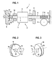
- a window regulator 2 is shown in a motor vehicle.
- the actuator 1 comprises a direction of rotation reversible, electric drive motor 3 with a motor armature 4, which is fixed in rotation on a shaft 5.
- Other components of the drive motor 3, as arranged in a pole housing 6 partially shown permanent magnets and a commutation are not shown for clarity.
- the shaft 5 is formed in a lying outside of the pole housing 6 section as a gear screw 7 with a worm thread 8 which meshes with a worm wheel 9, which is operatively connected to the window pane, not shown in a motor vehicle door, in particular by means of a cable.
- the shaft 5 is cantilevered.
- a radial bearing 10, 11 is arranged adjacent to each axial side of the motor armature 4.
- the the motor anchor Depending on the direction of rotation of the drive motor 4, the armature shaft 5 is supported either with its arranged in the left half of the drawing axial first end portion 14 at the first contact surface 12 or with its arranged in the right half of the drawing axial second end portion 15 on the second contact surface 13 outside of the pole housing 6 from.
- the two axial end portions 14, 15 are identical and realized by a respective spherical, ie convex shaped mushroom.
- the trained on a gear housing second contact surface 13 is exactly perpendicular to a longitudinal center axis L of the shaft 5 and is planar, so that the shaft 5 approximately punctiform (circular) in the region of its longitudinal central axis in the axial direction with a corresponding direction of rotation of the drive motor 3 at the second Support surface 13 is supported.
- a window is raised.
- the shaft 5 is supported with its first axial end portion 14 on the first contact surface 12 formed directly on the pole housing 6.
- the first contact surface 12 is formed by a peripheral edge 16 of a cylindrical recess 17, wherein the recess 17 is surrounded by a peripheral wall 20 (circumferential bead).
- the longitudinal central axis L 1 which is formed as a blind hole recess 17 is aligned with the longitudinal center axis L of the shaft 5, so that the annular abutment surface 12 is arranged concentrically to the longitudinal central axis L of the shaft 5.
- the annular abutment surface 12 at a distance r (friction radius) of the longitudinal central axis L and arranged in this embodiment of the longitudinal central axis L 1 of the opening 17, resulting in an increased self-locking.
- the self-locking of the actuator 1 is in the embodiment shown, when the shaft 5 is supported on the annular contact surface 12, so the window is raised, higher than in the opposite Direction of rotation driven drive motor, so when the shaft 5 is supported at least approximately punctiform on the opposite, flat contact surface 13.
- the annular contact surface 12 directly on the pole housing 6, but rather, for example, on a thrust washer which is fixed to the pole housing 6.
- the longitudinal center axis L 1 of the recess does not have to be aligned with the longitudinal center axis L of the shaft 5, but may include an angle of not equal to 90 ° with this.
- Fig. 2 shows a formed according to the invention thrust washer 18, which may be fixed for example to a pole housing or a transmission housing. It can be seen that the thrust washer 18 is at least approximately centrally penetrated by a recess 17 formed as a passage opening. An annular peripheral edge 16 of the cylindrical recess 17 on a front side in the drawing plane 19 of the thrust washer 18 forms an annular contact surface 12 for annular contact of a shaft with axial distance to the longitudinal center axis of the shaft. Both end faces of the thrust washer 18 are arranged parallel to each other in this embodiment.
- the thrust washer 18 can be fixed in such a way that the longitudinal central axis L 1 of the recess 17 is aligned with the shaft to be supported with the longitudinal central axis or encloses an angle with it.
- Fig. 3 an alternative running thrust washer 18 is shown with a recess 17 formed as a passage opening.
- the contact surface 12 is formed by a peripheral edge 16 of the recess 17 formed as a passage opening.
- the end face 19 is not perpendicular to the longitudinal central axis L 1 of the recess 17, but slightly angled to this, so that overall results in a substantially oval contoured contact surface 12 for a, in particular cantilevered shaft.
Landscapes
- Engineering & Computer Science (AREA)
- General Engineering & Computer Science (AREA)
- Mechanical Engineering (AREA)
- Power Engineering (AREA)
- Connection Of Motors, Electrical Generators, Mechanical Devices, And The Like (AREA)
- Power-Operated Mechanisms For Wings (AREA)
- Window Of Vehicle (AREA)
- Sliding-Contact Bearings (AREA)
Applications Claiming Priority (1)
| Application Number | Priority Date | Filing Date | Title |
|---|---|---|---|
| DE102007023389A DE102007023389A1 (de) | 2007-05-18 | 2007-05-18 | Wellenanlaufanordnung; Stellantrieb sowie Fensterhebereinrichtung |
Publications (2)
| Publication Number | Publication Date |
|---|---|
| EP1993190A2 true EP1993190A2 (fr) | 2008-11-19 |
| EP1993190A3 EP1993190A3 (fr) | 2009-01-14 |
Family
ID=39420675
Family Applications (1)
| Application Number | Title | Priority Date | Filing Date |
|---|---|---|---|
| EP08102756A Withdrawn EP1993190A3 (fr) | 2007-05-18 | 2008-03-19 | Palier de butée d'arbre, entraînement électrique et dispositif lève-vitre motorisé |
Country Status (3)
| Country | Link |
|---|---|
| EP (1) | EP1993190A3 (fr) |
| KR (1) | KR20080101777A (fr) |
| DE (1) | DE102007023389A1 (fr) |
Cited By (1)
| Publication number | Priority date | Publication date | Assignee | Title |
|---|---|---|---|---|
| CN105121912A (zh) * | 2013-01-08 | 2015-12-02 | 罗伯特·博世有限公司 | 轴止推装置以及伺服驱动机构 |
Families Citing this family (2)
| Publication number | Priority date | Publication date | Assignee | Title |
|---|---|---|---|---|
| DE102009010088A1 (de) * | 2009-02-24 | 2010-09-02 | Autoliv Development Ab | Reversibler Gurtstraffer |
| DE102010030377A1 (de) | 2010-06-23 | 2011-12-29 | Robert Bosch Gmbh | Wellenanordnung |
Citations (1)
| Publication number | Priority date | Publication date | Assignee | Title |
|---|---|---|---|---|
| DE3804219C2 (de) | 1988-02-11 | 1997-12-18 | Bosch Gmbh Robert | Stellantrieb |
Family Cites Families (4)
| Publication number | Priority date | Publication date | Assignee | Title |
|---|---|---|---|---|
| DE1675556A1 (de) * | 1968-02-22 | 1970-12-23 | Breitenbuecher Friedrich | Selbsthemmendes Schneckengetriebe |
| GB1565910A (en) * | 1976-12-02 | 1980-04-23 | Nippon Denso Co | Rotary electric machines |
| DE3150572A1 (de) * | 1981-12-21 | 1983-06-30 | Siemens AG, 1000 Berlin und 8000 München | Getriebemotor, insbesondere elektromotorischer fensterheber-antrieb |
| EP1369319A3 (fr) * | 2002-05-29 | 2005-05-04 | Siemens Aktiengesellschaft | Actuateur pour éléments de véhicule à moteur comportant un engrenage non réversible |
-
2007
- 2007-05-18 DE DE102007023389A patent/DE102007023389A1/de not_active Ceased
-
2008
- 2008-03-19 EP EP08102756A patent/EP1993190A3/fr not_active Withdrawn
- 2008-05-16 KR KR1020080045593A patent/KR20080101777A/ko not_active Ceased
Patent Citations (1)
| Publication number | Priority date | Publication date | Assignee | Title |
|---|---|---|---|---|
| DE3804219C2 (de) | 1988-02-11 | 1997-12-18 | Bosch Gmbh Robert | Stellantrieb |
Cited By (2)
| Publication number | Priority date | Publication date | Assignee | Title |
|---|---|---|---|---|
| CN105121912A (zh) * | 2013-01-08 | 2015-12-02 | 罗伯特·博世有限公司 | 轴止推装置以及伺服驱动机构 |
| CN105121912B (zh) * | 2013-01-08 | 2018-11-27 | 罗伯特·博世有限公司 | 轴止推装置以及伺服驱动机构 |
Also Published As
| Publication number | Publication date |
|---|---|
| DE102007023389A1 (de) | 2008-11-20 |
| KR20080101777A (ko) | 2008-11-21 |
| EP1993190A3 (fr) | 2009-01-14 |
Similar Documents
| Publication | Publication Date | Title |
|---|---|---|
| EP0175996B1 (fr) | Unité d'entraînement notamment pour le déplacement de glaces, de toits ouvrants, de sièges et d'accessoires d'automobiles similaires | |
| EP0918671B1 (fr) | Unite d'entrainement electrique | |
| EP0082375A2 (fr) | Moteur-réducteur, en particulier entraînement électromoteur pour lève-glaces | |
| DE102013015613B4 (de) | Elektrischer Antrieb | |
| EP2033859B1 (fr) | Dispositif de verrouillage pour un arbre de système de guidage | |
| EP1719237A1 (fr) | Unite d'entrainement a transmission | |
| WO2018019864A1 (fr) | Mécanisme de réglage pour véhicule automobile | |
| EP1009088A2 (fr) | Actionneur électrique pour véhicule à moteur | |
| DE102004002668A1 (de) | Vorrichtung zur Übertragung eines Drehmomentes von einem Motor zu einem Kompressor | |
| WO2006013022A1 (fr) | Element de protection destine a un palier | |
| EP1993190A2 (fr) | Palier de butée d'arbre, entraînement électrique et dispositif lève-vitre motorisé | |
| DE2646886A1 (de) | Antriebseinheit | |
| WO2022083982A1 (fr) | Unité d'engrenage à excentrique pour un générateur de force de freinage, et générateur de force de freinage | |
| EP0918931B1 (fr) | Groupe motopompe electrique | |
| EP1579125B1 (fr) | Unite d'entrainement de transmission | |
| DE10102516A1 (de) | Elektrischer Stellantrieb, insbesondere für Heizungs- Lüftungs- oder Klimaklappen in einem Kraftfahrzeug | |
| WO2012089418A1 (fr) | Dispositif de palier pour une unité d'entraînement, et entraînement de réglage présentant un dispositif de palier | |
| EP1958315B1 (fr) | Dispositif de blocage, unité d entraînement à engrenage comprenant un tel dispositif de blocage et procédé pour fabriquer une telle unité d entraînement à engrenage | |
| EP2147496B1 (fr) | Mécanisme de commande et système de lèvre-vitre | |
| DE102011085489A1 (de) | Spielkompensationseinrichtung sowie spielkompensierendes Axiallager, Motor und elektromotorischer Hilfsantrieb | |
| EP1794477B1 (fr) | Unite d'entrainement a engrenage comprenant un element de reglage | |
| WO2017140716A1 (fr) | Rétracteur de ceinture | |
| DE102018204226A1 (de) | Spindelantrieb und Komfortantrieb mit einem Spindelantrieb | |
| EP2102041A1 (fr) | Ensemble siège de palier pour immobilisation axiale et radiale | |
| EP4339487A1 (fr) | Roue dentée |
Legal Events
| Date | Code | Title | Description |
|---|---|---|---|
| PUAI | Public reference made under article 153(3) epc to a published international application that has entered the european phase |
Free format text: ORIGINAL CODE: 0009012 |
|
| AK | Designated contracting states |
Kind code of ref document: A2 Designated state(s): AT BE BG CH CY CZ DE DK EE ES FI FR GB GR HR HU IE IS IT LI LT LU LV MC MT NL NO PL PT RO SE SI SK TR |
|
| AX | Request for extension of the european patent |
Extension state: AL BA MK RS |
|
| PUAL | Search report despatched |
Free format text: ORIGINAL CODE: 0009013 |
|
| AK | Designated contracting states |
Kind code of ref document: A3 Designated state(s): AT BE BG CH CY CZ DE DK EE ES FI FR GB GR HR HU IE IS IT LI LT LU LV MC MT NL NO PL PT RO SE SI SK TR |
|
| AX | Request for extension of the european patent |
Extension state: AL BA MK RS |
|
| RIC1 | Information provided on ipc code assigned before grant |
Ipc: F16H 1/16 20060101ALI20081209BHEP Ipc: E05F 15/16 20060101ALI20081209BHEP Ipc: H02K 7/08 20060101AFI20080529BHEP |
|
| AKX | Designation fees paid | ||
| STAA | Information on the status of an ep patent application or granted ep patent |
Free format text: STATUS: THE APPLICATION IS DEEMED TO BE WITHDRAWN |
|
| 18D | Application deemed to be withdrawn |
Effective date: 20090715 |
|
| REG | Reference to a national code |
Ref country code: DE Ref legal event code: 8566 |