EP1993192A1 - Elektrische drehmaschine mit eingebauter steuerung - Google Patents
Elektrische drehmaschine mit eingebauter steuerung Download PDFInfo
- Publication number
- EP1993192A1 EP1993192A1 EP07708354A EP07708354A EP1993192A1 EP 1993192 A1 EP1993192 A1 EP 1993192A1 EP 07708354 A EP07708354 A EP 07708354A EP 07708354 A EP07708354 A EP 07708354A EP 1993192 A1 EP1993192 A1 EP 1993192A1
- Authority
- EP
- European Patent Office
- Prior art keywords
- circuit unit
- control circuit
- rotating machine
- electric rotating
- controller
- Prior art date
- Legal status (The legal status is an assumption and is not a legal conclusion. Google has not performed a legal analysis and makes no representation as to the accuracy of the status listed.)
- Granted
Links
Images





Classifications
-
- H—ELECTRICITY
- H02—GENERATION; CONVERSION OR DISTRIBUTION OF ELECTRIC POWER
- H02K—DYNAMO-ELECTRIC MACHINES
- H02K19/00—Synchronous motors or generators
- H02K19/16—Synchronous generators
- H02K19/36—Structural association of synchronous generators with auxiliary electric devices influencing the characteristic of the generator or controlling the generator, e.g. with impedances or switches
- H02K19/365—Structural association of synchronous generators with auxiliary electric devices influencing the characteristic of the generator or controlling the generator, e.g. with impedances or switches with a voltage regulator
-
- H—ELECTRICITY
- H02—GENERATION; CONVERSION OR DISTRIBUTION OF ELECTRIC POWER
- H02K—DYNAMO-ELECTRIC MACHINES
- H02K11/00—Structural association of dynamo-electric machines with electric components or with devices for shielding, monitoring or protection
- H02K11/04—Structural association of dynamo-electric machines with electric components or with devices for shielding, monitoring or protection for rectification
- H02K11/049—Rectifiers associated with stationary parts, e.g. stator cores
- H02K11/05—Rectifiers associated with casings, enclosures or brackets
-
- H—ELECTRICITY
- H02—GENERATION; CONVERSION OR DISTRIBUTION OF ELECTRIC POWER
- H02P—CONTROL OR REGULATION OF ELECTRIC MOTORS, ELECTRIC GENERATORS OR DYNAMO-ELECTRIC CONVERTERS; CONTROLLING TRANSFORMERS, REACTORS OR CHOKE COILS
- H02P9/00—Arrangements for controlling electric generators for the purpose of obtaining a desired output
- H02P9/009—Circuit arrangements for detecting rotor position
-
- H—ELECTRICITY
- H02—GENERATION; CONVERSION OR DISTRIBUTION OF ELECTRIC POWER
- H02P—CONTROL OR REGULATION OF ELECTRIC MOTORS, ELECTRIC GENERATORS OR DYNAMO-ELECTRIC CONVERTERS; CONTROLLING TRANSFORMERS, REACTORS OR CHOKE COILS
- H02P9/00—Arrangements for controlling electric generators for the purpose of obtaining a desired output
- H02P9/48—Arrangements for obtaining a constant output value at varying speed of the generator, e.g. on vehicle
-
- H—ELECTRICITY
- H02—GENERATION; CONVERSION OR DISTRIBUTION OF ELECTRIC POWER
- H02K—DYNAMO-ELECTRIC MACHINES
- H02K9/00—Arrangements for cooling or ventilating
- H02K9/02—Arrangements for cooling or ventilating by ambient air flowing through the machine
- H02K9/04—Arrangements for cooling or ventilating by ambient air flowing through the machine having means for generating a flow of cooling medium
- H02K9/06—Arrangements for cooling or ventilating by ambient air flowing through the machine having means for generating a flow of cooling medium with fans or impellers driven by the machine shaft
Definitions
- the present invention relates to a structure of a controller-integrated electric rotating machine in which a controller for controlling drive of an electric rotating machine is integrated.
- an idle-stop controller is disclosed in Patent Document 1 ( JP-A-2004-156589 ).
- the controller includes a switching element directly fixed to a substantially disk-shaped heat sink and a circuit board having a printed wiring layer fixed on the heat sink, and includes a control IC or the like on the circuit board.
- the heat sink is provided with double side frames on the entire outer periphery and the entire inner periphery attached thereto, and is fixed to an outer wall at the rear end of a bracket via the outer peripheral side frames. Resin is injected into a ring-shaped recess surrounded by the inner and outer peripheral frames of the heat sink, whereby the switching element, the circuit board and the control IC or the like are protected from salty mud water or the like.
- the controller has a cooling structure in which a resin cover is fixed to the bracket so as to cover the heat sink, so that cooling air flowing from an air-intake hole provided on the resin cover flows into the bracket while cooling the heat sink, and cools a stator winding and a rotor winding, and then flows out from the bracket.
- Patent Document 1 JP-A-2004-156589 (see Fig. 9 to Fig. 11, Paragraphs [0068] to [0072])
- the related art described above has a problem that electronic components having low heat resistance such as the control IC on the circuit board may become damaged due to heat when the circuit board is arranged in the vicinity of the heat sink on which the switching element as a heat-generating element is fixed. Furthermore, since it is integrally sealed with resin, there is also a problem that heat of the switching element is transferred through the resin and hence the temperature of the electronic components on the circuit board is increased.
- the substantially disk-shaped heat sink is employed as frames for sealing the switching element and the circuit board with resin, there is a problem that the shape and the layout of the heat sink are limited.
- a controller-integrated electric rotating machine includes an electric rotating machine having a rotor with a rotating shaft and a stator disposed so as to surround the rotor, a power circuit unit having switching elements for converting DC power to AC power for supplying AC power to the electric rotating machine, a control circuit unit for controlling the switching elements of the power circuit unit, and a rotational position detection sensor arranged on the rotating shaft for detecting the rotation of the rotating shaft, and the control circuit unit is disposed at a position where the power circuit unit is not disposed when viewed in the direction of the rotating shaft, and is disposed at a position shifted radially outward so as not to be overlapped with the rotational position detection sensor when viewed in the direction of the rotating shaft.
- the control circuit unit is arranged at the position where the power circuit unit is not arranged when viewed from the direction of the rotating shaft, a cooling structure for cooling the power circuit can be optimized irrespective of the shape of the control circuit, and flow of cooling air into the power circuit unit is not impaired by the existence of the control circuit unit.
- thermal adverse effects due to heat conduction from the power circuit unit or radiant heat can also be avoided on the control circuit unit.
- control circuit unit is arranged at the position shifted radially outward so as not to be overlapped with the rotational position detection sensor on the rotating shaft, the effect of noise from the control circuit unit on the rotational position detection sensor is reduced.
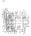
- Fig. 1 is a cross-sectional view showing a controller-integrated electric rotating machine according to a first embodiment of the present invention.
- a controller-integrated electric rotating machine 1 in this embodiment includes an electric rotating machine 2 which is an AC power generating electric motor (motor generator), a controller 3 for controlling drive of the electric rotating machine 2, a rotational position detection sensor 4 for detecting the rotational position of the electric rotating machine 2, and a connector 5 for external connection and a power source terminal 6.
- an electric rotating machine 2 which is an AC power generating electric motor (motor generator)
- a controller 3 for controlling drive of the electric rotating machine 2
- a rotational position detection sensor 4 for detecting the rotational position of the electric rotating machine 2
- a connector 5 for external connection and a power source terminal 6.
- the electric rotating machine 2 includes a front bracket 20 and a rear bracket 21 as a case, a rotating shaft 22 rotatably supported by the case via a bearing, a stator 23 being fixed to the case and having an armature winding 23a, a rotor 24 being fixed to the rotating shaft 22 and having a field winding 24a, a cooling fan 24b being fixed to both axial end surfaces of the rotor 24, a pulley 25 secured to a front end of the rotating shaft 22, a brush holder 26 mounted to the rear bracket 21 so as to position on an outer periphery of the rotating shaft 22 on the rear side, a pair of brushes 28 arranged in the brush holder 26 so as to in sliding contact with a pair of slip rings 27 mounted to the rear side of the rotating shaft 22, and the rotational position detection sensor 4 provided at a rear end of the rotating shaft 22.
- the electric rotating machine 2 is connected to a rotating shaft (not shown) of an engine via the pulley 25 and a belt (not shown).
- the controller 3 includes a power circuit unit 30 for converting DC power to AC power or AC power to DC power, a field circuit unit 31 for supplying field current to the field winding 24a, and a control circuit unit 32 for controlling the power circuit unit 30 and the field circuit unit 31, and is connected to an external peripherals via the external connector 5 and the power source terminal 6.
- the power circuit unit 30 includes a plurality of power elements (switching elements described later) 30a and 30b, and an inner heat sink 30g and an outer heat sink 30h which also serve as electrode members to be electrically connected to the power elements 30a and 30b. Connection between the respective power elements is achieved by a conductive member 30i insert-molded in resin and the heat sinks 30g and 30h, and electrical connection to the control circuit unit 32 is achieved via a relay wiring member 34b.
- the power circuit unit 30 is arranged on one end wall of the rear bracket 21 of the electric rotating machine 2, is laid out so as to surround the rotating shaft 22 as described later, and is covered by a cover 34 for preventing entry of foreign substances from the outside.
- the control circuit unit 32 includes a control circuit board 32a and a resin case 33 for storing the control circuit board 32a.
- the case 33 has a water-proof structure that can prevent entry of salty mud water into the control circuit board 32a by a water-proof cover 33a or the like, and is provided with a water-drain hole 33b for discharging water drops formed by dew condensation in the case 33.
- insulating properties and resistance to environment of the control circuit unit 32 are improved by filling insulated resin 33c in the case 33.
- the field circuit unit 31 may be mounted on the same board as the control circuit board 32a, and may be configured separately from the control circuit board 32a. In this example, it is mounted to the case 33 of the control circuit unit 32.
- the rotational position detection sensor 4 includes a stator 40 and a rotor 41, is disposed on the rotating shaft 22 which is rather rear side of the brushes 28, and is substantially sealed by a water-proof structure in the same manner as the control circuit unit 32.
- the water-proof structure is achieved by a seal packing 42 mounted to the rear bracket 21, and a water-drain hole 43 is provided like the case 33.
- the rotational position detection sensor 4 is used for vector control when electrically driving the electric rotating machine 2.
- the external connector 5 is disposed in the vicinity of the control circuit unit 32, and is electrically connected to the control circuit unit 32.
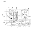
- Fig. 2 is a circuit diagram for explaining the operation of the electric rotating machine 2 in this embodiment.
- the electric rotating machine 2 as the AC power generating electric motor includes the armature winding 23a for the stator 23 and the field winding 24a for the rotor 24, and the armature winding 23a of the stator 23 includes coils of three phases (U-phase, V-phase, and W-phase).
- the power circuit unit 30 includes an inverter having three sets of a switching element (power transistor, MOSFET, IGBT, etc.) 30a which constitutes an upper arm 30A with a parallel diode and a switching element 30b which constitutes a lower arm 30B with a parallel diode connected in series, and the three sets are arranged in parallel.
- a switching element power transistor, MOSFET, IGBT, etc.
- a capacitor 102 is connected to the inverter in parallel. Ends of the respective phases of the armature winding 23a are connected respectively to mid nodes between the switching elements 30a of the upper arms 30A and the switching elements 30b of the lower arms 30B which are connected in series via the AC wiring. A positive terminal and a negative terminal of a battery 101 are connected to a positive side and a negative side of the power circuit unit 30 via a series wiring.
- the field circuit unit 31 includes two semiconductor elements 31a and 31b connected in series via the brush 28 and the slip ring 27 (see Fig. 1 ) with the intermediary of the field winding 24a, and a flywheel diode 31d connected in parallel to a shunt resistor 31c.
- a drain of the upper semiconductor element 31a is connected the heat sink 30g connected to the power source terminal 6, and a source of the lower semiconductor element 31b is grounded to the rear bracket 21 via the shunt resistor 31c.
- the control circuit unit 32 controls switching operation of the switching element 30a of the upper arm 30A and the switching element 30b of the lower arm 30B of the power circuit unit 30, and controls the field circuit unit 31 for adjusting the field current to be flown through the field winding 24a of the rotor.
- Fig. 2 general circuit operation of the electric rotating machine 2 in the present embodiment will be described.
- the control circuit unit 32 controls the respective switching elements 30a and 30b of the power circuit unit 30 with the ON/OFF control to convert the DC power to three-phase AC power.
- the thee-phase AC power is supplied to the armature winding 23a of the electric rotating machine 2 as the AC power generating electric motor.
- the field circuit unit 31 supplies field current to the field winding 24a of the rotor 24 on the basis of a command from the control circuit unit 32.
- Linkage of magnetic flux generating around the field winding 24a and current flowing in the armature winding 23a of the stator 23 generates drive torque.
- the drive torque drives the rotor 24 to rotate, which is transmitted from the pulley 25 to a crankshaft of the engine via a belt (not shown), so that the engine is started.
- the cooling fan 24b fixed to the rotor 24 generates cooling air flow F by the rotation of the rotor 24 of the electric rotating machine 2.
- the cooling air flow F is sucked from inlet holes 34a of the cover 34 on the rear side, passes between heat discharge fins of the heat sinks 30g and 30h provided along the direction of the rotating shaft, and cools the respective switching elements 30a and 30b. Then, the cooling air flow F passed through a ventilation hole of the rear bracket 21 is bent in the radial direction by 90° and is discharged while cooling the stator 23.
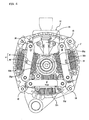
- Fig. 3 is a front view showing the controller-integrated electric rotating machine according to the first embodiment of the present invention when viewed from the direction of the rotating shaft
- Fig. 4 is a front view corresponding to Fig. 3 in a state in which the cover 34 of the electric rotating machine 2 and the case 33 of the control circuit unit 32 are removed.
- the controller 3 is disposed in the axial direction of the one end wall of the rear bracket 21, and the control circuit unit 32 of the controller 3 has a substantially rectangular shape when viewed in the direction of the rotating shaft.
- the control circuit unit 32 is laid out at a position (double dashed line 32 in Fig. 4 ) where the power circuit unit 30 is not disposed when viewed in the direction of the rotating shaft.
- the control circuit unit 32 is disposed at a position shifted radially outward so as not to be overlapped with the rotational position detection sensor 4 disposed on the rotating shaft 22.
- the control circuit unit 32 has the substantially rectangular shape when viewed in the direction of the rotating shaft.
- the shape of the control circuit unit 32 is not limited thereto. It may be any shape as long as it has one side or two sides for arranging the respective connecting portions intensively at least when viewed in the direction of the rotating shaft.
- control circuit unit 32 since the control circuit unit 32 is arranged at the position where the power circuit unit 30 is not disposed when viewed in the direction of the rotating shaft, the flow of the cooling air into the power circuit unit 30 is not impaired by the existence of the control circuit unit 32.
- the positions or the sizes of the inlet holes 34a provided on the cover 34 which covers the power circuit unit 30 can be optimized, so that the power circuit unit 30 can be cooled sufficiently.
- thermal adverse effects due to heat conduction from the power circuit unit 30 or radiant heat on the control circuit unit 32 can also be avoided.
- control circuit unit 32 is disposed at the position shifted radially outward so as not to be overlapped with the rotational position detection sensor 4 on the rotating shaft 22, the effect of noise from the control circuit unit 32 on the rotational position detection sensor 4 is reduced.
- control circuit unit 32 since the connecting portions with respect to the power circuit unit 30 and the rotational position detection sensor 4 are intensively provided on the one side 320a of the control circuit unit 32, wiring design of the pattern circuit of the control circuit unit 32 can easily be performed and, simultaneously, assembleability is improved. Therefore, the control circuit unit 32 can be downsized.
- control circuit unit 32 since the connecting portions with respect to the power circuit unit 30 and the rotational position detection sensor 4 are intensively provided on the one side 320a of the control circuit unit 32, and the connecting portions with respect to the external connector 5 are arranged on the another side 320b of the control circuit unit 32, which is different from the one side shown above, the wiring design of the pattern circuit of the control circuit unit 32 is further facilitated, so that the circuit configuration can be rationalized, and hence the control circuit unit 32 in a reliable and simple configuration can be obtained.
- control circuit unit 32 Since the control circuit unit 32 is formed into the substantially rectangular shape when viewed in the direction of the rotating shaft, flexibility in arrangement of elements such as a custom IC or a drive to be mounted is improved. Therefore, the pattern design of the control circuit unit 32 can be rationalized, whereby the possibility of downsizing of the control circuit unit 32 is further increased. In addition, by providing the connecting portions intensively on the side of the control circuit unit 32, assembleability and reliability such that soldering work of the connecting portions is achieved easily, and the joint state of the solder can easily be checked are improved.
- the cover 34 having the holes 34a for cooling the power circuit unit 30 and the case 33 for storing the control circuit unit 32 are provided, and the power circuit unit 30 and the control circuit unit 32 are thermally separated, they are not thermally affected from each other and hence high cooling property can be secured.
- the interior of the case 33 for storing the control circuit unit 32 is sealed with resin to provide a water-proof property to the control circuit unit 32.
- the insulating property and the resistance to environment of the control circuit unit 32 are improved, and heat conductivity of the elements on the control circuit board 32a to the outside can be improved with the employment of the heat conductive resin, so that increase in temperature can be restrained.
- the switching elements which constitute the power circuit unit 30 are divided into the three-phase portions of U, V and W.
- the respective portions each include the pair of heat sinks, the inner heat sink 30g and the outer heat sink 30h.
- the respective heat sinks 30g and 30h each include the several switching elements 30a and 30b as discrete type power elements in parallel (not shown).
- the heat sinks 30g and 30h each include a cooling fin extending along a cooling air channel in the direction of the rotating shaft. In this configuration, the cooling efficiency of the respective switching elements 30a and 30b of the power circuit unit 30 increases, and the power circuit unit 30 can be downsized and optimized.
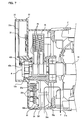
- Fig. 5 is a cross-sectional view showing part of the controller-integrated electric rotating machine according to a second embodiment of the present invention.
- Fig. 6 is a front view of the controller-integrated electric rotating machine according to the second embodiment of the present invention when viewed in the direction of the rotating shaft.
- the position of the external connector 5 with respect to the control circuit unit 32 is the position (radially outer side) opposing the connecting portions with respect to the power circuit unit 30 and the rotational position detection sensor 4 (the radially inner side).
- the connecting portions with the power circuit unit 30, the field circuit unit 31, and the rotational position detection sensor 4 are provided intensively to the long side 320a which is the radially inner side of the control circuit unit 32 in substantially the rectangular shape, and the connecting portions with respect to the external connector 5 are provided on the short side 320b on the circumferentially outside.
- the surface area occupied by the control circuit unit 32 when viewed in the direction of the rotating shaft can be increased in the circumferential direction, and hence the amount of projection of the external connector 5 in the radial direction can be reduced.
- Connection wirings of the external connector 5, the rotational position detection sensor 4 and the power circuit unit 30 can be arranged rationally, and hence the control circuit unit 32 can be downsized.
- the case 33 for storing the control circuit unit 32 is formed integrally with the cover 34 of the power circuit unit 30 or the external connector 5 with resin. With such a configuration, the number of components can be reduced, and the necessity to fix the case 33 of the control circuit unit 32 and the cover 34 of the power circuit unit 30 individually can be eliminated, so that assembleability is improved.
- the cover 34 of the power circuit unit 30 includes the relay wiring member 34b which connects the power circuit unit 30 and the control circuit unit 32 by insert molding
- the case 33 for storing the control circuit unit 32 includes a relay wiring member which connects the external connector 5 and the control circuit unit 32 by insert molding.
- the relay wiring member 34b which connects the power circuit unit 30 and the control circuit unit 32, and the relay wiring member which connects the external connector 5 and the control circuit unit 32 are reliably provided with a high insulating property, and handling of the case 33 after molding is easily, which improves assembleability.
- the case 33 for storing the control circuit unit 32 has a common space used as a space for storing the control circuit board 32a and a space for storing the rotational position detection sensor 4.
- the rotational position detection sensor 4 by itself and a lead wire 40a lead therefrom can be water-proofed with ease.
- the case 33 for storing the control circuit unit 32 has a water-proof structure which prevents entry of salty mud water into the control circuit board 32a and the rotational position detection sensor 4 by the water-proof cover 33a or the like, and is provided with the water-drain hole 33b for discharging water drops formed by dew condensation in the case 33.
- the insulating property and the resistance to environment of the control circuit unit 32 and the rotational position detection sensor 4 are improved.
- a relay wiring member 40b for connecting the control circuit unit 32 and the rotational position detection sensor 4 on the case 33 for storing the control circuit unit 32 by insert molding (not shown).
- the vibration proof and insulating property of the lead wire 40a of the rotational position detection sensor 4 can be improved.
- Fig. 7 is a cross-sectional view showing the controller-integrated electric rotating machine according to a third embodiment of the present invention.
- Fig. 8 is a front view corresponding to Fig. 7 in a state in which the cover of the electric rotating machine and the case of the control circuit unit are removed when viewed in the direction of the rotating shaft.
- cooling air flows into the power circuit unit 30 in the substantially axial direction through the holes 34a of the cover 34 from behind the controller-integrated electric rotating machine 1, and the respective heat sinks 30g and 30h having the switching elements 30a and 30b as the power elements each are provided with the cooling fins extending along the cooling air channel in the axial direction.
- the cooling air is sucked from the inlet hole 34a provided on a side wall in the radial direction of the cover 34 of the power circuit unit 30.
- the heat sinks 30g and 30h having the switching elements 30a and 30b mounted thereon are formed into a horseshoe shape, and are each provided with a cooling fin along the cooling air channel in the radial direction of the rotating shaft. In this configuration, the positions and the sizes of the air channel holes for cooling the power circuit unit 30 can be optimized irrespective of the shape of the control circuit unit 32.
- the connections between the respective switching elements are achieved by the conductive member 30i insert-molded in resin, and the heat sinks 30g and 30h.
- the conductive member 30i used for connecting between the respective switching elements may be connected directly to the control circuit unit 32.
- the relay wiring member which connects the control circuit unit 32 and the power circuit unit 30 can be omitted, so that the number of components and the number of connection nodes are reduced owing to the aggregation of the components, whereby the assembleability is improved and the insulating property is also improved.
- the case 33 for the control circuit unit 32 includes the relay wiring member 40b for connecting the control circuit unit 32 and the rotational position detection sensor 4 with insert molding, so that the vibration proof and insulating property of the lead wire 40a of the rotational position detection sensor 4 are improved.
- Fig. 9 is a cross-sectional view of the controller-integrated electric rotating machine according to a fourth embodiment of the present invention.
- the case 33 for storing the control circuit unit 32 is integrally formed with the cover 34 of the power circuit unit 30 or the external connector 5 with resin.
- the invention is not limited thereto.
- the storing case 33 of the control circuit unit 32 and the external connector 5 may be formed integrally with the brush holder 26 with resin.
- the control circuit unit 32 is achieved by, disposing the control circuit unit 32 on the brush holder 26, soldering the wiring and then effecting resin sealing with insulated resin 33c for improving resistance to environment. Since the above-described processes can be performed with the single brush holder 26, workability and assembleability of the electric rotating machine are further improved.
- the resin sealing with the insulated resin 33c heat of the control circuit unit 32 is transferred to the brush holder 26, and is indirectly cooled by the entire brush holder.
- the present invention can be widely applied to the controller-integrated electric rotating machine provided with the power circuit unit and the control circuit unit.
Landscapes
- Engineering & Computer Science (AREA)
- Power Engineering (AREA)
- Control Of Eletrric Generators (AREA)
- Motor Or Generator Frames (AREA)
- Motor Or Generator Cooling System (AREA)
Applications Claiming Priority (2)
| Application Number | Priority Date | Filing Date | Title |
|---|---|---|---|
| JP2006043301A JP4402057B2 (ja) | 2006-02-21 | 2006-02-21 | 制御装置一体型回転電機 |
| PCT/JP2007/052463 WO2007097222A1 (ja) | 2006-02-21 | 2007-02-13 | 制御装置一体型回転電機 |
Publications (3)
| Publication Number | Publication Date |
|---|---|
| EP1993192A1 true EP1993192A1 (de) | 2008-11-19 |
| EP1993192A4 EP1993192A4 (de) | 2014-04-09 |
| EP1993192B1 EP1993192B1 (de) | 2017-05-17 |
Family
ID=38437261
Family Applications (1)
| Application Number | Title | Priority Date | Filing Date |
|---|---|---|---|
| EP07708354.1A Ceased EP1993192B1 (de) | 2006-02-21 | 2007-02-13 | Elektrische drehmaschine mit eingebauter steuerung |
Country Status (5)
| Country | Link |
|---|---|
| US (2) | US8198763B2 (de) |
| EP (1) | EP1993192B1 (de) |
| JP (1) | JP4402057B2 (de) |
| CN (1) | CN101317318B (de) |
| WO (1) | WO2007097222A1 (de) |
Cited By (8)
| Publication number | Priority date | Publication date | Assignee | Title |
|---|---|---|---|---|
| FR2931315A1 (fr) * | 2008-05-19 | 2009-11-20 | Mitsubishi Electric Corp | Machine electrique tournante integree avec un dispositif de commande |
| FR2937805A1 (fr) * | 2008-10-27 | 2010-04-30 | Mitsubishi Electric Corp | Machine electrique rotative a commande integree. |
| WO2011020665A3 (de) * | 2009-08-18 | 2012-03-29 | Robert Bosch Gmbh | Elektrische maschine |
| EP2298622A4 (de) * | 2008-07-16 | 2012-11-14 | Mitsubishi Electric Corp | Elektrische servolenkvorrichtung und elektromotor mit integrierter steuervorrichtung |
| FR3014614A1 (fr) * | 2013-12-09 | 2015-06-12 | Mitsubishi Electric Corp | Machine electrique rotative dotee d'un convertisseur de puissance |
| EP2773029A4 (de) * | 2011-10-25 | 2015-09-09 | Mitsubishi Electric Corp | Rotationselektromaschine |
| WO2015149987A1 (de) * | 2014-03-31 | 2015-10-08 | Lemförder Electronic GmbH | Treiberbaugruppe |
| EP2840687A4 (de) * | 2012-04-16 | 2016-03-09 | Mitsubishi Electric Corp | Dynamoelektrische maschine |
Families Citing this family (33)
| Publication number | Priority date | Publication date | Assignee | Title |
|---|---|---|---|---|
| JP5104334B2 (ja) * | 2008-01-22 | 2012-12-19 | 株式会社島津製作所 | 真空ポンプ |
| JP2010004598A (ja) * | 2008-06-18 | 2010-01-07 | Mitsubishi Electric Corp | 制御装置一体型回転電機 |
| JP5349888B2 (ja) * | 2008-10-10 | 2013-11-20 | 日立オートモティブシステムズ株式会社 | 電動アクチュエータの制御装置 |
| JP5183566B2 (ja) * | 2009-05-15 | 2013-04-17 | 三菱電機株式会社 | 回転位置検出装置およびレーザ加工機 |
| JP4903243B2 (ja) * | 2009-05-19 | 2012-03-28 | 三菱電機株式会社 | 発電機装置 |
| JP5327646B2 (ja) * | 2009-06-24 | 2013-10-30 | 株式会社デンソー | 電子回路内蔵型モータ |
| JP5292266B2 (ja) * | 2009-12-03 | 2013-09-18 | 日立オートモティブシステムズ株式会社 | スタータ |
| CN103098352B (zh) * | 2010-09-15 | 2016-06-29 | 三菱电机株式会社 | 电力转换装置、电动机、空调和换气送风设备 |
| CN103688450B (zh) * | 2011-07-22 | 2016-10-26 | 株式会社日立产机系统 | 泵装置 |
| US9667124B2 (en) * | 2011-08-08 | 2017-05-30 | Mitsubishi Electric Corporation | Controller-integrated electric rotating machine with brush restricting elements and assembling and disassembling methods of the same |
| DE112012003901B4 (de) * | 2011-09-20 | 2022-05-05 | Mitsubishi Electric Corp. | Mechanisch und elektrisch integriertes Modul |
| IN2014CN00516A (de) * | 2011-11-09 | 2015-04-03 | Mitsubishi Electric Corp | |
| JP5729268B2 (ja) * | 2011-11-17 | 2015-06-03 | 株式会社デンソー | 車両用回転電機 |
| JP5464224B2 (ja) * | 2012-03-14 | 2014-04-09 | 株式会社安川電機 | モータ駆動装置および車両 |
| JP5476407B2 (ja) * | 2012-03-14 | 2014-04-23 | 株式会社安川電機 | モータ駆動装置および車両 |
| JP5815846B2 (ja) * | 2012-03-30 | 2015-11-17 | 本田技研工業株式会社 | 回転電機 |
| CN104137396B (zh) * | 2012-04-16 | 2017-05-03 | 三菱电机株式会社 | 旋转电机 |
| JP5373936B1 (ja) * | 2012-06-05 | 2013-12-18 | 三菱電機株式会社 | 制御装置一体型回転電機 |
| JP5528505B2 (ja) * | 2012-06-14 | 2014-06-25 | 三菱電機株式会社 | 回転電機 |
| JP5484531B2 (ja) * | 2012-08-09 | 2014-05-07 | 三菱電機株式会社 | 交流発電機 |
| JP5748917B2 (ja) * | 2012-08-28 | 2015-07-15 | 三菱電機株式会社 | 電動式駆動装置および電動式駆動装置の製造方法 |
| JP5511929B2 (ja) * | 2012-10-24 | 2014-06-04 | 三菱電機株式会社 | 交流発電機 |
| JP2014236616A (ja) * | 2013-06-04 | 2014-12-15 | 三菱電機株式会社 | 回転電機 |
| SG2013051982A (en) * | 2013-07-04 | 2015-02-27 | Pteris Global Ltd | Motor drive controller |
| US20160156243A1 (en) * | 2013-07-12 | 2016-06-02 | Mitsuba Corporation | Motor apparatus |
| JP5721794B2 (ja) * | 2013-08-26 | 2015-05-20 | 三菱電機株式会社 | 制御装置一体型回転電機 |
| JP5901678B2 (ja) * | 2014-03-27 | 2016-04-13 | 株式会社豊田中央研究所 | 情報処理装置、情報記憶装置、及び回転電機の制御装置 |
| DE102014205957A1 (de) * | 2014-03-31 | 2015-10-01 | Lemförder Electronic GmbH | Treiberbaugruppe |
| JP6213397B2 (ja) | 2014-07-03 | 2017-10-18 | 株式会社デンソー | 回転電機 |
| EP3200286B1 (de) * | 2014-09-24 | 2021-08-04 | Mitsubishi Electric Corporation | Elektronische steuerungsvorrichtung für fahrzeug und motorantriebsvorrichtung |
| JP6543907B2 (ja) * | 2014-10-08 | 2019-07-17 | 三菱自動車工業株式会社 | 車両用モータ装置 |
| JP7244586B2 (ja) * | 2021-07-26 | 2023-03-22 | 本田技研工業株式会社 | 電気的接続構造 |
| JP2025041127A (ja) * | 2023-09-13 | 2025-03-26 | 株式会社デンソー | 駆動装置 |
Family Cites Families (33)
| Publication number | Priority date | Publication date | Assignee | Title |
|---|---|---|---|---|
| JPS6036701B2 (ja) * | 1979-12-14 | 1985-08-22 | 株式会社デンソー | 車両用交流発電機 |
| JPH0119584Y2 (de) * | 1980-05-09 | 1989-06-06 | ||
| JP3514319B2 (ja) * | 1993-07-26 | 2004-03-31 | 株式会社デンソー | 回転電機 |
| JP3543881B2 (ja) * | 1995-11-08 | 2004-07-21 | 株式会社デンソー | 交流発電機 |
| US5949166A (en) * | 1997-09-25 | 1999-09-07 | Denso Corporation | Rectifying apparatus for an automotive AC generator |
| US6252320B1 (en) * | 1999-05-24 | 2001-06-26 | Unit Parts Company | Alternator system |
| CN2393259Y (zh) * | 1999-11-11 | 2000-08-23 | 华戈扬 | 双相驱动双绕组直流无刷电动机 |
| JP3949369B2 (ja) * | 2000-10-20 | 2007-07-25 | 三菱電機株式会社 | 車両用交流発電機 |
| JP3949370B2 (ja) * | 2000-11-08 | 2007-07-25 | 三菱電機株式会社 | 車両用交流発電機 |
| CN2521819Y (zh) * | 2001-12-27 | 2002-11-20 | 信息产业部电子第二十一研究所 | 吸尘器用直流无刷电动机 |
| JP3593102B2 (ja) * | 2002-01-08 | 2004-11-24 | 三菱電機株式会社 | 電動パワーステアリング装置 |
| US6992409B2 (en) * | 2002-03-15 | 2006-01-31 | Denso Corporation | Liquid-cooled rotary electric machine integrated with an inverter |
| FR2842042A1 (fr) * | 2002-07-04 | 2004-01-09 | Valeo Equip Electr Moteur | Module de controle et de puissance d'un alterno-demarreur integrale |
| JP4082310B2 (ja) | 2002-10-15 | 2008-04-30 | 株式会社デンソー | アイドルストップ制御装置 |
| US7411324B2 (en) | 2002-10-28 | 2008-08-12 | Toyota Jidosha Kabushiki Kaisha | Generator-motor |
| EP1557932A1 (de) | 2002-10-28 | 2005-07-27 | Toyota Jidosha Kabushiki Kaisha | Generator/motor |
| JP4003611B2 (ja) * | 2002-10-28 | 2007-11-07 | トヨタ自動車株式会社 | 発電電動装置 |
| JP4073759B2 (ja) * | 2002-11-07 | 2008-04-09 | 三菱電機株式会社 | 車両用回転電機 |
| JP2005039950A (ja) * | 2003-07-16 | 2005-02-10 | Denso Corp | 制御装置一体型発電電動機 |
| DE102004007395B4 (de) * | 2003-02-18 | 2016-11-03 | Denso Corporation | Motorgenerator |
| JP4147987B2 (ja) * | 2003-03-17 | 2008-09-10 | 株式会社日立製作所 | 多相式交流回転電機 |
| JP4523240B2 (ja) * | 2003-04-23 | 2010-08-11 | 三菱電機株式会社 | 車両用電動発電装置 |
| JP3974080B2 (ja) * | 2003-06-16 | 2007-09-12 | 株式会社デンソー | インバータ一体型電動発電機 |
| JP4239723B2 (ja) * | 2003-07-24 | 2009-03-18 | トヨタ自動車株式会社 | 発電電動装置を備える駆動システムおよび発電電動装置の制御をコンピュータに実行させるためのプログラムを記録したコンピュータ読取り可能な記録媒体 |
| JP2005117708A (ja) * | 2003-10-02 | 2005-04-28 | Denso Corp | 制御手段一体型交流モータ |
| JP2005328690A (ja) | 2004-04-12 | 2005-11-24 | Hitachi Ltd | 車両用回転電機 |
| JP2005348494A (ja) | 2004-06-02 | 2005-12-15 | Mitsubishi Electric Corp | 回転電機 |
| JP4351592B2 (ja) * | 2004-07-15 | 2009-10-28 | 三菱電機株式会社 | 制御装置一体型回転電機 |
| JP4275614B2 (ja) | 2004-12-10 | 2009-06-10 | 三菱電機株式会社 | 車両用回転電機 |
| JP2006174541A (ja) * | 2004-12-13 | 2006-06-29 | Mitsubishi Electric Corp | 回転電機 |
| JP4926409B2 (ja) * | 2005-03-17 | 2012-05-09 | 三菱電機株式会社 | 交流発電機 |
| JP4279810B2 (ja) * | 2005-08-11 | 2009-06-17 | 三菱電機株式会社 | 車両用回転電機 |
| US7960880B2 (en) * | 2005-12-16 | 2011-06-14 | Mitsubishi Electric Corporation | Automotive electric motor-generator with radial plates and circuit boards disposed in a fan shape in a common plane around shaft of rotor |
-
2006
- 2006-02-21 JP JP2006043301A patent/JP4402057B2/ja not_active Expired - Fee Related
-
2007
- 2007-02-13 EP EP07708354.1A patent/EP1993192B1/de not_active Ceased
- 2007-02-13 WO PCT/JP2007/052463 patent/WO2007097222A1/ja not_active Ceased
- 2007-02-13 CN CN2007800003703A patent/CN101317318B/zh not_active Expired - Fee Related
- 2007-02-13 US US12/089,589 patent/US8198763B2/en not_active Expired - Fee Related
-
2012
- 2012-02-14 US US13/372,741 patent/US8704415B2/en not_active Expired - Fee Related
Cited By (12)
| Publication number | Priority date | Publication date | Assignee | Title |
|---|---|---|---|---|
| FR2931315A1 (fr) * | 2008-05-19 | 2009-11-20 | Mitsubishi Electric Corp | Machine electrique tournante integree avec un dispositif de commande |
| EP2298622A4 (de) * | 2008-07-16 | 2012-11-14 | Mitsubishi Electric Corp | Elektrische servolenkvorrichtung und elektromotor mit integrierter steuervorrichtung |
| EP2623394A1 (de) * | 2008-07-16 | 2013-08-07 | Mitsubishi Electric Corporation | Elektrische Servolenkvorrichtung und Elektromotor mit integrierter Steuerungsvorrichtung |
| FR2937805A1 (fr) * | 2008-10-27 | 2010-04-30 | Mitsubishi Electric Corp | Machine electrique rotative a commande integree. |
| WO2011020665A3 (de) * | 2009-08-18 | 2012-03-29 | Robert Bosch Gmbh | Elektrische maschine |
| CN102577047A (zh) * | 2009-08-18 | 2012-07-11 | 罗伯特·博世有限公司 | 电机 |
| EP2773029A4 (de) * | 2011-10-25 | 2015-09-09 | Mitsubishi Electric Corp | Rotationselektromaschine |
| US10069374B2 (en) | 2011-10-25 | 2018-09-04 | Mitsubishi Electric Corporation | Rotary electric machine having an heat sink with semiconductor modules attached |
| EP2840687A4 (de) * | 2012-04-16 | 2016-03-09 | Mitsubishi Electric Corp | Dynamoelektrische maschine |
| FR3014614A1 (fr) * | 2013-12-09 | 2015-06-12 | Mitsubishi Electric Corp | Machine electrique rotative dotee d'un convertisseur de puissance |
| WO2015149987A1 (de) * | 2014-03-31 | 2015-10-08 | Lemförder Electronic GmbH | Treiberbaugruppe |
| US9917533B2 (en) | 2014-03-31 | 2018-03-13 | Lemförder Electronic GmbH | Driver assembly |
Also Published As
| Publication number | Publication date |
|---|---|
| WO2007097222A1 (ja) | 2007-08-30 |
| US20090243407A1 (en) | 2009-10-01 |
| EP1993192B1 (de) | 2017-05-17 |
| JP4402057B2 (ja) | 2010-01-20 |
| EP1993192A4 (de) | 2014-04-09 |
| US8198763B2 (en) | 2012-06-12 |
| CN101317318B (zh) | 2011-03-30 |
| US8704415B2 (en) | 2014-04-22 |
| CN101317318A (zh) | 2008-12-03 |
| JP2007228641A (ja) | 2007-09-06 |
| US20120181903A1 (en) | 2012-07-19 |
Similar Documents
| Publication | Publication Date | Title |
|---|---|---|
| EP1993192B1 (de) | Elektrische drehmaschine mit eingebauter steuerung | |
| JP4275614B2 (ja) | 車両用回転電機 | |
| JP5202573B2 (ja) | 車両用制御装置一体型回転電機 | |
| CN101006633B (zh) | 旋转电机 | |
| JP4123436B2 (ja) | インバータ一体型交流モータ | |
| CN1913297B (zh) | 车辆用旋转电机 | |
| US7397223B2 (en) | Inverter-integrated electrical rotating machine | |
| JP6621491B2 (ja) | 回転電機 | |
| CN1913298B (zh) | 车辆用旋转电机 | |
| CN103620925B (zh) | 旋转电机 | |
| CN113141088B (zh) | 旋转电机 | |
| CN101331667B (zh) | 车辆用电动发电机 | |
| JP4889517B2 (ja) | 回転電機装置 | |
| WO2007069547A1 (ja) | 車両用電動発電機 | |
| JP4815473B2 (ja) | 回転電機 | |
| JP4229138B2 (ja) | 制御装置及び制御装置一体型回転電機 | |
| JP7002621B1 (ja) | 制御装置一体型回転電機 | |
| CN112385123A (zh) | 旋转电机 | |
| JP4121093B2 (ja) | 車両用電動発電機 | |
| JP2005348494A (ja) | 回転電機 |
Legal Events
| Date | Code | Title | Description |
|---|---|---|---|
| PUAI | Public reference made under article 153(3) epc to a published international application that has entered the european phase |
Free format text: ORIGINAL CODE: 0009012 |
|
| 17P | Request for examination filed |
Effective date: 20071011 |
|
| AK | Designated contracting states |
Kind code of ref document: A1 Designated state(s): DE FR |
|
| RBV | Designated contracting states (corrected) |
Designated state(s): DE FR |
|
| DAX | Request for extension of the european patent (deleted) | ||
| A4 | Supplementary search report drawn up and despatched |
Effective date: 20140306 |
|
| RIC1 | Information provided on ipc code assigned before grant |
Ipc: H02K 11/00 20060101AFI20140228BHEP Ipc: H02K 5/10 20060101ALI20140228BHEP Ipc: H02K 5/18 20060101ALI20140228BHEP Ipc: H02P 9/04 20060101ALI20140228BHEP Ipc: H02K 5/22 20060101ALI20140228BHEP |
|
| 17Q | First examination report despatched |
Effective date: 20150615 |
|
| GRAP | Despatch of communication of intention to grant a patent |
Free format text: ORIGINAL CODE: EPIDOSNIGR1 |
|
| INTG | Intention to grant announced |
Effective date: 20161206 |
|
| GRAS | Grant fee paid |
Free format text: ORIGINAL CODE: EPIDOSNIGR3 |
|
| GRAA | (expected) grant |
Free format text: ORIGINAL CODE: 0009210 |
|
| AK | Designated contracting states |
Kind code of ref document: B1 Designated state(s): DE FR |
|
| REG | Reference to a national code |
Ref country code: DE Ref legal event code: R096 Ref document number: 602007051022 Country of ref document: DE |
|
| REG | Reference to a national code |
Ref country code: FR Ref legal event code: PLFP Year of fee payment: 12 |
|
| REG | Reference to a national code |
Ref country code: DE Ref legal event code: R097 Ref document number: 602007051022 Country of ref document: DE |
|
| PLBE | No opposition filed within time limit |
Free format text: ORIGINAL CODE: 0009261 |
|
| STAA | Information on the status of an ep patent application or granted ep patent |
Free format text: STATUS: NO OPPOSITION FILED WITHIN TIME LIMIT |
|
| 26N | No opposition filed |
Effective date: 20180220 |
|
| PGFP | Annual fee paid to national office [announced via postgrant information from national office to epo] |
Ref country code: DE Payment date: 20200129 Year of fee payment: 14 |
|
| PGFP | Annual fee paid to national office [announced via postgrant information from national office to epo] |
Ref country code: FR Payment date: 20200113 Year of fee payment: 14 |
|
| REG | Reference to a national code |
Ref country code: DE Ref legal event code: R119 Ref document number: 602007051022 Country of ref document: DE |
|
| PG25 | Lapsed in a contracting state [announced via postgrant information from national office to epo] |
Ref country code: DE Free format text: LAPSE BECAUSE OF NON-PAYMENT OF DUE FEES Effective date: 20210901 Ref country code: FR Free format text: LAPSE BECAUSE OF NON-PAYMENT OF DUE FEES Effective date: 20210228 |