EP1993243A1 - Terminal - Google Patents
Terminal Download PDFInfo
- Publication number
- EP1993243A1 EP1993243A1 EP07738870A EP07738870A EP1993243A1 EP 1993243 A1 EP1993243 A1 EP 1993243A1 EP 07738870 A EP07738870 A EP 07738870A EP 07738870 A EP07738870 A EP 07738870A EP 1993243 A1 EP1993243 A1 EP 1993243A1
- Authority
- EP
- European Patent Office
- Prior art keywords
- transmission
- terminal
- packet
- group
- control unit
- Prior art date
- Legal status (The legal status is an assumption and is not a legal conclusion. Google has not performed a legal analysis and makes no representation as to the accuracy of the status listed.)
- Granted
Links
- 230000005540 biological transmission Effects 0.000 claims abstract description 550
- 238000012546 transfer Methods 0.000 claims abstract description 331
- 238000004891 communication Methods 0.000 claims description 72
- 239000000969 carrier Substances 0.000 claims description 27
- 238000001514 detection method Methods 0.000 claims description 27
- 238000012937 correction Methods 0.000 claims description 19
- 238000012544 monitoring process Methods 0.000 claims description 12
- 230000010076 replication Effects 0.000 claims description 10
- 238000004364 calculation method Methods 0.000 claims description 6
- 230000003362 replicative effect Effects 0.000 claims description 6
- 230000010354 integration Effects 0.000 claims description 2
- 238000005304 joining Methods 0.000 claims description 2
- 238000007726 management method Methods 0.000 description 309
- 238000012545 processing Methods 0.000 description 225
- 238000000034 method Methods 0.000 description 44
- 230000006870 function Effects 0.000 description 31
- 238000011084 recovery Methods 0.000 description 23
- 238000013500 data storage Methods 0.000 description 22
- 238000005516 engineering process Methods 0.000 description 12
- 230000007246 mechanism Effects 0.000 description 10
- 230000004044 response Effects 0.000 description 9
- 238000012986 modification Methods 0.000 description 8
- 230000004048 modification Effects 0.000 description 8
- 238000009826 distribution Methods 0.000 description 7
- 230000001174 ascending effect Effects 0.000 description 6
- 230000000694 effects Effects 0.000 description 6
- 238000010586 diagram Methods 0.000 description 5
- 238000003860 storage Methods 0.000 description 4
- 230000007423 decrease Effects 0.000 description 3
- 238000011156 evaluation Methods 0.000 description 3
- 230000008859 change Effects 0.000 description 2
- 230000003247 decreasing effect Effects 0.000 description 2
- 238000005457 optimization Methods 0.000 description 2
- 230000008569 process Effects 0.000 description 2
- 230000008707 rearrangement Effects 0.000 description 2
- 239000004065 semiconductor Substances 0.000 description 2
- 230000005236 sound signal Effects 0.000 description 2
- 101100172132 Mus musculus Eif3a gene Proteins 0.000 description 1
- 238000003491 array Methods 0.000 description 1
- 230000006866 deterioration Effects 0.000 description 1
- 238000011161 development Methods 0.000 description 1
- 238000004519 manufacturing process Methods 0.000 description 1
- 238000005259 measurement Methods 0.000 description 1
- 230000003287 optical effect Effects 0.000 description 1
- 230000009467 reduction Effects 0.000 description 1
- 230000007480 spreading Effects 0.000 description 1
- 238000003892 spreading Methods 0.000 description 1
- 238000012549 training Methods 0.000 description 1
- 239000002699 waste material Substances 0.000 description 1
Images













Classifications
-
- H—ELECTRICITY
- H04—ELECTRIC COMMUNICATION TECHNIQUE
- H04L—TRANSMISSION OF DIGITAL INFORMATION, e.g. TELEGRAPHIC COMMUNICATION
- H04L12/00—Data switching networks
- H04L12/02—Details
- H04L12/16—Arrangements for providing special services to substations
- H04L12/18—Arrangements for providing special services to substations for broadcast or conference, e.g. multicast
-
- H—ELECTRICITY
- H04—ELECTRIC COMMUNICATION TECHNIQUE
- H04B—TRANSMISSION
- H04B7/00—Radio transmission systems, i.e. using radiation field
- H04B7/14—Relay systems
- H04B7/15—Active relay systems
- H04B7/155—Ground-based stations
- H04B7/15528—Control of operation parameters of a relay station to exploit the physical medium
- H04B7/15542—Selecting at relay station its transmit and receive resources
-
- H—ELECTRICITY
- H04—ELECTRIC COMMUNICATION TECHNIQUE
- H04L—TRANSMISSION OF DIGITAL INFORMATION, e.g. TELEGRAPHIC COMMUNICATION
- H04L47/00—Traffic control in data switching networks
- H04L47/10—Flow control; Congestion control
- H04L47/15—Flow control; Congestion control in relation to multipoint traffic
Definitions
- IP multicast packets need to be transferred stably and at high speed.
- the following technique is one technique to realize a fast and high quality transmission system using a medium which is not intended for high frequency digital communication.
- An actual measurement of the frequency characteristic of transmission paths of media such as electric light wires or wireless communication paths in an arbitrary environment provides the following: the frequency characteristic of each transmission path changes very dynamically along time, and the characteristics of sub carriers of the transmission path are significantly varied.
- the terminal further comprises a transmission time calculation section for calculating a transmission time required for transmitting data to the relay device based on the transmission parameter set for each group; and the transfer management section classifies the transmission paths into one or more groups again based on the calculated transmission time.
- the terminal further comprises a monitoring section for monitoring the number of received multicast packets, the number of transmitted multicast packets, and a transmission data size.
- the band management section releases a part of resource already assigned and saves again a part of the resource of the transmission path for the new multicast address.
- the transfer management section revises the received packet.
- the integrated circuit acts as a transmission parameter setting function for evaluating characteristics of a transmission path up to the relay device and setting a transmission parameter on at least one of a transmittable information amount per a predetermined time length and an error correction strength; a transfer management function for classifying transmission paths into one or more groups based on similarity of the set transmission parameter, the transmission paths being used for connecting a plurality of relay devices to the communication medium, and when a multicast packet is received, for sending the received packet; a packet replication function for replicating the number of packets which is equal to the number of the groups from the received packet; and a transmission function for sending each of the plurality of replicated packets on a unit of a group, based on the transmission parameter set for each group.
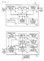
- the control unit 204 controls the entire operation of the terminal 100.
- the control unit 204 includes a control unit main part 251, a transmission time calculation section 252, a grouping control unit 253, a multiple access map creation section 254, a packet type detection section 255, a group management information management section 256, a transmission policy application section 257, and a transmission path estimation control unit 258.
- the control unit main part 251 performs main control of the control unit 204 and also operates as an external interface for communication between the control unit 204 and other elements.
- the transmission time calculation section 252 calculates a theoretical transmission time of each group and of the entire transmission.
- the grouping control unit 253 controls grouping into transmission groups.
- the multiple access map creation section 254 creates transmission maps in multicast and broadcast.
- the packet type detection section 255 identifies the specific type of a packet received from the network 101 or a packet received from the network 103.
- the group management information management section 256 refers to and edits group management information stored in the data storage section 202 and also manages a timer on the group management information to manage the groups.
- the transmission policy application section 257 operates in association with the group management information management section 256 to set a transfer policy.
- the transmission path estimation control unit 258 executes transmission path estimation.
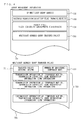
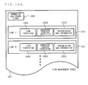
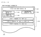
- the multicast address group transfer policy 705 includes transfer policy setting 721 indicating whether or not a transfer policy is set, a number 722 of the temporary maps registered for this multicast group, and transmission information 723 including the temporary map No., transmission capability, band reservation information and link information.
- the multicast address group transfer policy 705 includes a number of units of transmission information 723 corresponding to the number of the temporary maps.
- the "transmission path parameter” refers to a collection of information on error correction setting such as Reed-Solomon, Viterbi or the like and on the strength thereof, and the transmission map.
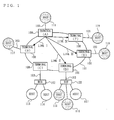
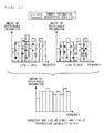
- FIG. 5 shows transmission maps of the links I through IV (transmission maps 301 through 304) shown in FIG. 1 .
- the horizontal axis represents the frequency
- the vertical axis represents the amount of information which can be described.
- the terminal 100 adopts the link optimization modulation/demodulation, by which the frequency band used in the network 101 is divided into 10 sub carriers 305 and the amount of information described in each sub carrier in a predetermined time length is set.
- the number of the sub carriers into which the terminal 100 divides the frequency band used in the network 101 may not be necessarily 10, and may be less than 10, or 11 or greater.
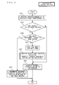
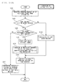
- FIG. 8 illustrates the processing of the control unit 204 when the terminal 100 according to the present invention receives a multicast packet from the network 103.
- the control unit 204 of the terminal 100 starts the processing shown in FIG. 8 .
- step S401 the control unit 204 receives a notification from the external interface section 203 that the multicast packet has been received. Upon receipt of the notification that the multicast packet has been received, the control unit 204 advances to the processing in step S402.
- step S405 using the IGMP (MLD) JOIN message wait timer, the control unit 204 can determine that no host belonging to this IP multicast address group is connected to the network 101. In this case, the control unit 204 can control the terminal 100 not to transfer this multicast packet. This provides an effect that the terminal 100 does not unnecessarily increase the traffic of the network 101.
- MLD IGMP
- step S407 the control unit 204 sets the modulation/demodulation format for sending, to the network 101, the multicast packet to be transferred to the diversity mode, and changes the setting so as to perform a broadcast transfer to the network 101.
- the mode by which the terminal 100 transfers a multicast packet is defined as the diversity mode, but the mode is not limited to this needless to say.
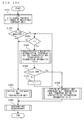
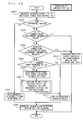
- step S1004 the transfer management section 206 compares i and k. When i is smaller than k, the transfer management section 206 advances to step S1005; whereas when i is not smaller than k, the transfer management section 206 advances to step S1003.
- step S1023 the transfer management section 206 increments the global variant x by 1.
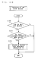
- FIG. 10D illustrates the detailed operation in step S1008.
- the functions of the terminal 100 according to the present invention have been described.
- the operation of the terminal 100 when a host requests the network formed of the terminals 100 for a transfer of an IP multicast packet will be described more specifically and sequentially. It is assumed that the hosts 111 through 119 have IGMP protocol v2 or higher mounted thereon.
- the IP multicast packet corresponding to the multicast group G is broadcast in the network 101 and therefore reaches all the hosts 112 through 119.
- step S1023 the control unit 204 of the terminal (A) increments x by 1.
- the value of x is 1.
- step S1023 When the processing in the step S1023 is finished, the processing of the control unit 204 of the terminal (A) in step S1003 is finished. Thus, the control unit 204 of the terminal (A) advances to step S1009.
- the host 112 issues an IGMP JOIN message MK. Because the host 112 is connected to the terminal (B), the terminal (B) transmits the IGMP JOIN message MK issued by the host 112 to the network 101 by broadcast in accordance with the processing shown in FIG. 8 .
- the terminal (B) operates in the same manner as when the host 115 transmits the IGMP JOIN message MJ to the terminal (D). Accordingly, the terminal (A) transfers the IGMP JOIN message MK, issued by the host 112 and transferred from the terminal (B), to the host 111 in accordance with the operation described below.
- the control unit 204 of the terminal (A) advances to step S503 as in the case of processing the IGMP JOIN message MJ issued by the host 115.
- step S503 the operation of the control unit control unit 204 of the terminal (A) will be described.
- step S1002 the control unit 204 of the terminal (A) refers to the packet type 704 included in the group management information 701 and the band reservation information table shown in FIG. 6 to determine the loss recovery level corresponding to the packet type 704.
- the packet type 704 of the IGMP JOIN message MK issued by the host 112 is "phone voice", which is the same as the packet type 704 of the IGMP JOIN message MJ issued by the host 115.
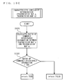
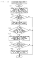
- step S1005 the control unit 204 of the terminal (A) performs the processing shown in FIG. 10C .
- step S1031 the control unit 204 of the terminal (A) calculates the ratio of commonly described information between the temporary map (0) currently registered and the transmission map 301 of the link I connecting the terminal (A) and the terminal (B). After calculating the ratio of commonly described information, the control unit 204 of the terminal (A) advances to step S1032.
- the control unit 204 of the terminal (A) compares the similarity between the transmission map 302 registered as the temporary map (0) and the transmission map 301 in the form of parameters. In step S1032, the control unit 204 of the terminal (A) compares the calculated ratio of commonly described information and the threshold value THR.
- the result of the characteristic similarity determination is FALSE.
- step S1007 the control unit 204 of the terminal (A) increments i by 1.
- the control unit 204 of the terminal (A) returns to step S1004.
- step S1004 because i is 1 and k is 1, the control unit 204 of the terminal (A) determines "NO" and advances to the processing in step S1003.
- step S1003 the control unit 204 of the terminal (A) registers the transmission map 301 in correspondence with a temporary map (1) and thus updates the multicast address group transfer policy 705 corresponding to the multicast address group GA.
- the control unit 204 of the terminal (A) performs the processing shown in FIG. 10B which illustrates the detailed operation in step S1003 and thus sets "2" for the number 722 of the registered temporary maps included in the multicast address group transfer policy 705.
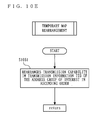
- step S1009 the control unit 204 of the terminal (A) compares the transmission capability included in transmission information #1 and that of the transmission information #2, and rearranges the transmission information based on the comparison result.
- the link information included in the transmission information #1 and the link information included in the transmission information #2 each include one identifier of each of the terminals 100. Accordingly, for transferring a multicast packet corresponding to the multicast address group GA to the network 103, the terminal (A) transmits the multicast packet to the terminals (D) and (B) by unicast via the network 101.
- step S502 because the received message is an IGMP JOIN message, the terminal (D) determines "YES" and advances to the processing in step S506.
- step S503 the terminal (D) performs the processing shown in FIG. 10A .
- step S1001 the terminal (D) sets the local variable i to 0, x to 1 and k to 1, and advances to the processing in step S1002.
- the terminal (D) refers to FIG. 6 to determine that the loss recovery level of the IGMP JOIN message is 7, and applies the multicast address group transfer policy 705 by which a multicast packet is sent by unicast to all the terminals.
- the terminal (D) sets a transmission map of each link in the terminals (A), (B), (C), (E) and (F) and thus prepares the multicast address group transfer policy 705.
- the terminal (D) can create this by performing the processing shown in FIG. 10A for all the terminals 100 connected to the network.
- the terminal (F) transmits the IGMP JOIN message ML issued by the host 119 by broadcast via the network 101 and thus transfers the message to the terminal (A).
- the processing of the terminal (A) when receiving the IGMP JOIN message ML will be described with reference to FIG. 9 again.
- the terminal (A) advances to step S503 as when receiving the IGMP JOIN message MJ.
- the terminal (A) performs the processing shown in FIG. 10A .
- step S1002 the control unit 204 of the terminal (A) refers to the packet type 704 included in the group management information 701 and the band reservation information table shown in FIG. 6 to determine the loss recovery level corresponding to the packet type 704.
- the packet type 704 of the IGMP JOIN message ML issued by the host 119 is "phone voice", which is the same as the packet type 704 of the IGMP JOIN message MJ issued by the host 115.
- control unit 204 of the terminal (A) makes a correspondence between the loss recovery level of the "phone voice" of the band reservation information table shown in FIG. 6 and the loss recovery level definition shown in FIG. 7 and determines that ACK is not required, and thus advances to step S1004.
- the terminal (A) compares the similarity between the transmission map 302 registered as the temporary map (0) and the transmission map 304 in the form of parameters.
- the terminal (A) compares the calculated ratio of commonly described information and the threshold value THR.
- the ratio of commonly described information ⁇ THR and thus the result of the characteristic similarity determination is FALSE.
- step S1007 the control unit 204 of the terminal (A) increments i by 1.
- the control unit 204 of the terminal (A) returns to step S1004.
- the terminal (A) compares the similarity between the transmission map 301 registered as the temporary map (1) and the transmission map 301 in the form of parameters.
- the terminal (A) compares the calculated ratio of commonly described information and the threshold value THR.
- the result of the characteristic similarity determination is TRUE.
- step S1041 the terminal (A) sets a multiple access map.
- the multiple access map is created by calculating a logical product of information description areas of mutually corresponding sub carriers in two transmission maps.
- the terminal (A) calculates the logical product of the information description areas of mutually corresponding sub carriers in the transmission map 301 and the transmission map 304 compared in step S1005, and thus creates a multiple access map.
- the logical product of the information description areas of mutually corresponding sub carriers in the transmission map 301 and the transmission map 304 is a common information description area 1101 shown in FIG. 11 .
- step S1002 the terminal (A) performs the same processing as for transferring the IGMP JOIN message ML issued by the host 112 and determines that the message is of the packet type which does not require ACK, and thus advances to step S1004.
- step S1004 because i is 0 and k is 2, the control unit 204 of the terminal (A) determines "YES" and advances to step S1005.
- step S1008 the terminal (A) performs multiple access map setting.
- the operation of the terminal (A) of setting a multiple access map will be described with reference to FIG. 10D again and also FIG. 11 .
- the terminal (A) receives a request from the network 103 to transfer a packet addressed to the multicast address group GA.
- the link information of the transmission information #1 includes only the link II, and therefore the terminal (A) transmits the packet to the link II by unicast by applying the transmission map 302.
- the link information of the transmission information #2 includes the link I and the link IV, and therefore the terminal (A) transmits the packet to the links I and IV by multiple access by applying the multiple access map 1202.
- the terminal (A) performs the same processing as when receiving the IGMP JOIN message MJ, and advances to step S503.
- the detailed operation of the terminal (A) will be described with reference to FIG. 10A again which illustrates the detailed operation in step S503.
- step S1007 the control unit 204 of the terminal (A) increments i by 1.
- the terminal (A) returns to step S1004.
- step S1004 because i is 1 and k is 2, the control unit 204 of the terminal (A) determines "YES" and advances to the processing in step S1005.
- step S1005 the terminal (A) performs the processing shown in FIG. 10C again.
- the terminal (A) calculates the ratio of commonly described information between the temporary map (1) and the transmission map 303 of the link III connecting the terminal (A) and the terminal (E). After calculating the ratio of commonly described information, the terminal (A) advances to step S1032.
- step S1004 because i is 2 and k is 2, the terminal (A) determines "NO" and advances to the processing in step S1003.
- the terminal (A) issues the multicast packets in the order of the level of the transmission capability described in the transmission information, from a higher level to a lower level.
- the transmission delay is unlikely to occur because the transmission characteristic of the transmission path is good.
- control unit 204 of the terminal (A) determines in step S507 whether to transfer or discard the received IGMP (MLD) message as described above will be described, hereinafter.
- the first host When a host detects the issuance of an IGMP (MLD) REPORT message from another host belonging to the same sub network, the first host does not issue an IGMP (MLD) REPORT message. In other words, if a host different from the host which issued the IGMP (MLD) REPORT message cannot detect the issuance of the IGMP (MLD) REPORT message, such a different host issues an IGMP (MLD) REPORT message.
- MLD IGMP
- a mechanism by which the terminals 100 other than the terminal (A) do not transfer the IGMP (MLD) REPORT message outside the network 101 is provided. Accordingly, all the receiving hosts (one host connected to each of all the terminals belonging to the multicast group G; the host 112, the host 115 or 116, the host 118, the host 119) issue an IGMP (MLD) REPORT message, and the IGMP (MLD) REPORT message reaches the terminal 100 (A).
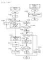
- FIG. 14A is a flowchart including the processing on the IGMP (MLD) LEAVE message.
- the flowchart shown in FIG. 14A includes step S1401 in addition to the flowchart shown in FIG. 9 .
- step S1402 the terminal (A) determines whether the multicast packet transferred from another terminal 100 is an IGMP LEAVE message or not. When the packet is an IGMP LEAVE message, the terminal (A) advances to step S1403; whereas when the packet is not an IGMP LEAVE message, the terminal (A) terminates the processing.
- step S1403 the terminal (A) determines whether or not the group management information 701 has been created.
- the terminal (A) terminates the processing; whereas when the group management information 701 for the multicast address group GA is existent, the terminal (A) advances to step S1404.
- step S1404 the terminal (A) updates the group management information 701 of the multicast group address.
- step S1417 the terminal (A) deletes the group management information in which no temporary map is registered. After deleting the group management information, the terminal (A) terminates the processing shown in FIG. 14C and advances to step S504 shown in FIG. 14A .
- step S1411 the control unit 204 of the terminal (A) searches for, and retrieves, the terminal identifier of the terminal (D) and the host identifier of the host 116 from the group management information corresponding to the multicast address group GA.
- step S1412 the terminal identifier of the terminal (D) and the host identifier of the host 116 from the group management information corresponding to the multicast address group GA.
- step S1412 the terminal identifier of the terminal (D) and the host identifier of the host 116 are registered in the group management information 701 corresponding to the multicast address group GA. Therefore, the control unit 204 of the terminal (A) determines "YES" and advances to step S1413.
- step S1414 the control unit 204 of the terminal (A) determines whether or not a host identifier other than the deleted host identifier of the host 116 is recorded in the transmission information #1.
- the identifier of the host 115 is left in the transmission information #1. Therefore, the terminal (A) determines "YES" and terminates the processing shown in FIG. 14C .
- the control unit 204 of the terminal (A) determines a host to which the multicast packet does not need to be transferred and thus does not unnecessarily transmit a multicast packet. Therefore, an unnecessary increase of the traffic in the network 101 can be avoided.
- control unit 204 of the terminal (A) may start a transmission path estimation mechanism to the link indicated by the transmission information at the timing of step S1414.
- the control unit 204 of the terminal (A) making a transmission path estimation on the link I a more efficient transfer can be realized.
- the terminal (A) has such a function, and also in the case where the terminal (A) has a mechanism of periodically starting a transmission path estimation mechanism for each unit of transmission information, the traffic of the network 101 can be effectively reduced.
- the external interface section 203 included in the terminal 100 has a function of monitoring and measuring the input packet rate from the external interface section 203 for each multicast address group, and a function of comparing the content of the band reservation of the multicast address group included in the group management information 701 and the input packet rate from the network 103 and determining whether or not the comparison result has exceeded a certain threshold value.
- the terminal 100 can prevent the waste of the band occupied by the band reservation when the packet to be transferred is not input, or can prevent the quality reduction occurring due to the shortage of the band occupied by the band reservation with respect to the actual packet rate.
- a high quality transmission system can be automatically realized.
- the terminal 100 can perform the following operation in order to realize automatic band reservation without causing an overload.
- the band reservation by the band reservation management section 207 may be performed in the form of band adjustment.
- the band reservation information may be managed as information included in the multicast address group transfer policy 705.
- the packet type 704 is "control”
- the corresponding minimum rate, maximum rate and tolerated delay are not specified. Therefore, it is not necessary to make a reservation for band guarantee.
- the access may be controlled by distributed control type media access control or the like such as the CSMA/CA format.
- the algorithm shown in FIG. 10A shows a method of making a determination from a registered temporary map having a lower transmission capability and thus setting the multiple access map uniquely
- the transfer management section 206 may create all the multiple access maps for a link to which the data needs to be transferred, and find a transmission method which requires the shortest transmission time to such a link, among the transmission methods such as unicast, multicast, broadcast and the like, based on the transmission capability of the transmission map and the total time calculated by taking the number of issued frames in the network 101 into account.
- step S503 in FIG. 9 carried out in the first embodiment is modified.
- step S11701 the transfer management section 206 registers the link between the terminal 100 which issued the received IGMP (MLD) message and this terminal 100 in the link management table 1061, and increments the number N of registered links by 1.
- MLD IGMP
- the link array L is an array for storing the link identifier 10621 or the like.
- the array H[N] [N] is an array for storing the group to be set in the transfer policy for transferring a multicast packet in correspondence with the link information.
- the array H[N][N] stores information on the group, among all the groups, which gives the shortest transmission time min_time and information on the link corresponding to such a group.
- the variable h_gr_num is a variable for storing the number of rows of the array H[N][N].
- the value of the variable h_gr_num represents the number of the groups.
- step S11707 the transfer management section 206 performs the processing shown in FIG. 15C to determine whether TRUE or FALSE is stored in the data storage section 202.
- the transfer management section 206 advances to step S11709; whereas when FALSE is stored in the data storage section 202, the transfer management section 206 advances to step S11708.
- step S11801 the transfer management section 206 sets variable i to 0 and advances to the processing in step S11802.
- step S11811 the transfer management section 206 increments the value of the variable j by 1 and returns to the step S11808.
- step S11813 the transfer management section 206 increments the value of the group identifier gr_numby 1 and advances to step S11814.
- step S11814 the transfer management section 206 returns FALSE.
- step S11901 the transfer management section 206 sets the variable i and variable tmp_time to 0, and advances to step S11902.
- step S11906 the transfer management section 206 increments the variable i by 1 and returns to the processing in step S11902.
- the transfer management section 206 reaches step S11906 when it is determined that the variable i is not smaller than the group identifier gr_num in step S11902.
- step S11906 the transfer management section 206 compares the value of variable min_time and the value of the variable tmp_time. When the value of the variable tmp_time is smaller than the value of the variable min_time, the transfer management section 206 advances to step S11907; whereas when the value of the variable tmp_time is not smaller than the value of the variable min_time, the transfer management section 206 terminates the processing shown in FIG. 15D .
- step S11001 the transfer management section 206 initializes the variable i to 0 and advances to step S11002.
- step S11002 the transfer management section 206 compares the variable i and the variable h_gr_num. When the variable i is smaller than the variable h_gr_num, the transfer management section 206 advances to the processing in step S11003. When the variable i is larger than the variable h_gr_num, the transfer management section 206 terminates the processing shown in FIG. 15E and advances to step S11712 shown in FIG. 15B .
- step S11003 the transfer management section 206 calculates a logical product of each sub carrier in the transmission map of all the links included in array H[i][], and thus creates a multiple access map. After creating the multiple access map, the transfer management section 206 advances to step S11004.
- step S11004 the transfer management section 206 performs the same processing as in step S1022 shown in FIG. 10B , and sets the calculated multiple access map in step S11003 in the multicast address group transfer policy 705.
- step S11005 the transfer management section 206 notifies the multicast address group and the multiple access map to all the terminals corresponding to all the links included in the array H[N][N]. After notifying the multicast address group and the multiple access map, the transfer management section 206 returns to step S11002.
- the speed of multiple access transmission is increased by a simpler method than in the first embodiment.
- the first embodiment is especially effective in a medium, such as an existing dedicated line or the like, which does not have much varied frequency characteristic on the transmission path.
- the basic structure of a terminal 100 according to the second embodiment is the same as that according to the first embodiment. Thus, FIG. 1 through FIG. 3 are incorporated in this embodiment and the description of the structure will be repeated. As in the first embodiment, it is assumed that the network 103 is conformed to the Ethernet (registered trademark) standard. In the second embodiment, also as in the first embodiment, a multiple carrier transmission by DMT is performed in the network 101.
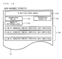
- FIG. 16 shows a structure of group management information 1701 used by the terminal 100 in the second embodiment.
- the group management information 1701 includes an IP multicast group address 1702, a transmission map No. 1703, a transmission capability 1704, a number 1705 of registered links, and a plurality of units of link information 1706.
- Each of the units of the link information 1706 includes an addressee terminal identifier and a host identifier.
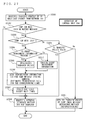
- the external interface section 203 of the terminal 100 Upon receipt of a multicast packet to be transferred to the network 101 from the network 103, the external interface section 203 of the terminal 100 refers to the header information of the received multicast packet. When the packet is a multicast packet, the external interface section 203 gives the received packet to the control unit 204.
- step S1502 the control unit 204 determines whether or not the received packet is one of an IGMP JOIN message and an IGMP REPORT message. When the received packet is either an IGMP JOIN message or an IGMP REPORTmessage, the control unit 204 advances to step S1503. Otherwise, the control unit 204 advances to the processing in step S1505.
- step S1503 the control unit 204 determines whether or not the control unit 204 grasps the source terminal, which has issued the multicast packet to be transferred to the multicast address. The method by which the control unit 204 grasps the source terminal will be described later.
- step S1504 the control unit 204 makes a setting such that a packet replicated from the received multicast packet is transmitted by unicast to the source terminal that the control unit 204 grasps.
- the control unit 204 advances to step S1508.
- step S1505 the control unit 204 determines whether or not a multiple access map corresponding to the multicast packet to be transferred has been created. The method for creating a multiple access map will be described later.
- the control unit 204 advances to step S1507. Otherwise, the control unit 204 advances to step S1506.
- step S1506 the control unit 204 makes a setting such that the packet to be transferred is transmitted by broadcast of the diversity mode within the network 101.
- the control unit 204 advances to step S1508.
- step S1507 the control unit 204 applies the multiple access map corresponding to the multicast packet to be transferred and advances to step S1508.
- step S1508 the control unit 204 requests the transmission/reception section 201 that the multicast packet requested to be transferred should be to transferred to the network 101 in accordance with the set mode.
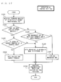
- FIG. 18 is a flowchart illustrating the details of processing performed by the control unit 204 when the terminal receives a multicast packet in the second embodiment of the present invention.
- step S1602 the control unit 204 determines whether or not the received packet is one of an IGMP (MLD) JOIN message and an IGMP (MLD) REPORT message.
- the control unit 204 advances to step S1603. Otherwise, the control unit 204 advances to step S1606.
- step S1603 when the group management information 1701 regarding the multicast address to which the multicast packet is to be transferred has not been created, the control unit 204 creates the group management information 1701 regarding the multicast address to which the multicast packet is to be transferred. Namely, the control unit 204 creates the group management information 1701 using the IP multicast group address 1702 and the link information 1706 taken out from the received multicast packet. The control unit 204 sets "1" for the number 1705 of the registered links included in the group management information 1701.
- control unit 204 may set the identifier of the terminal 100 which requested a transfer of the IGMP (MLD) message as the addressee terminal identifier of the link information, and set the identifier of the host which issued the IGMP (MLD) message as the host identifier.
- IGMP IGMP
- the control unit 204 adds the link information 1706.
- the identifier of the terminal 100 which requested the transfer of the IGMP (MLD) message and the identifier of the host which issued the IGMP (MLD) message are set.
- the control unit 204 increments the value of the number 1705 of the registered links by 1.
- step S1604 the control unit 204 selects the transmission map having the lowest transmission capability among the obtained transmission maps, and updates the group management information 1701 using the selected transmission map.
- the control unit 204 sets the transmission map No. of the transmission map determined to have the lowest transmission capability as the transmission map No. 1703, and sets the transmission capability obtained from the transmission map determined as above as the transmission capability 1704.
- the resource for holding the transmission maps which were not selected by the control unit 204 may be released.
- step S1606 the control unit 204 stores the multicast address included in the multicast packet requested to be transferred and the identifier of the terminal which requested the transfer in association with each other.
- the control unit 204 makes the above-described determination in step S1504 based on the multicast address and the identifier of the terminal which are stored by performing the processing in step S1606.
- control unit 204 performs transmission path estimation only on the link to which the multicast packet is requested to be transferred.
- control unit 204 compares the transmission capability of the link on which the transmission path estimation has been performed and the already set transmission capability 1704.
- the control unit 204 selects the transmission map having a lower transmission capability, and updates the transmission map No. 1703 and the transmission capability 1704 based on the No. and the transmission capability of the selected transmission map. After updating the group management information 1701, the resource for holding the transmission maps which were not selected may be released.
- control unit 204 can reduce the load on, for example, the common band which is caused by performing the transmission path estimation on all the links, or the resource such as a memory area or the like temporarily used in order to create the transmission map.
- the host 111 issued a multicast packet addressed to a multicast group address HA (IP multicast group H). It is also assumed that the hosts belonging to the IP multicast group H, i.e., the hosts which are operating an application for receiving or sending a packet to be distributed in the IP multicast group H are the hosts 111, 112, 115, 116, 118 and 119.
- step S1502 the control unit 204 determines that the received message is not an IGMP (MLD) message and advances to step S1505.
- MLD IGMP
- step S1505 because the multiple access map corresponding to the multicast group H of the received multicast packet has not been created, the control unit 204 advances to step S1506.
- step S1508 the control unit 204 requests the transmission/reception section 201 to transfer the multicast packet to the network 101.
- the terminal (A) transmits the multicast packet transmitted by the host 111 to the network 101 by broadcast of the diversity mode. As a result, the received packet can be transferred to all the terminals.
- the transmission/reception section 201 of the terminal (B) receives a frame including the multicast packet transmitted from the terminal (A) by broadcast from the network 101. Because the frame received by the terminal (B) includes the multicast packet, the control unit 204 performs the following processing in accordance with the flowchart shown in FIG. 18 .
- step S1602 because the received multicast packet is not an IGMP (MLD) message, the control unit 204 advances to step S1606.
- IGMP MLD
- step S1606 the control unit 204 stores the multicast address H in correspondence with the identifier of the source terminal which issued the multicast packet, and advances to step S1605.
- step S1605 the control unit 204 requests the external interface section 203 to transfer the multicast packet.
- the multicast packet transferred from the terminal (B) reaches the host 112.
- the host 112 wishes to receives a packet of the multicast group address HA and so issues an IGMP JOIN message MB.
- the IGMP JOIN message MB is a packet addressed to the multicast group address HA and is given to the external interface section 203 of the terminal (B).
- the packet received by the external interface section 203 is the multicast packet transmitted from the host 112. Accordingly, the control unit 204 of the terminal (B) performs the following processing in accordance with the flowchart shown in FIG. 17 .
- step S1503 the control unit 204 manages the source terminal of the IP address group (step S1606 shown in FIG. 18 ), and so advances to step S1504.
- step S1504 the control unit 204 makes a setting such that the IGMP (MLD) JOIN message MB requested to be transferred is transmitted by unicast to the terminal (A), and advances to step S1508.
- MLD IGMP
- the terminal 100 manages, by a unit of a multicast address, the terminal sending a multicast data packet. Therefore, the terminal 100 can transmit an IGMP JOIN message, an IGMP REPORT message and the like corresponding to each multicast address by unicast to the network 101.
- the terminal 100 transmits a multicast packet by unicast, ACK is easily managed, and an IGMP JOIN message or an IGMP REPORT message can be sent with certainty.
- the terminal 100 does not transmit an IGMP REPORT message to anything other than the source terminal which issued a multicast data packet in the network 101. Therefore, the terminal 100 connected to a host belonging to the multicast group in the network 103 issues an IGMP REPORT message.
- the terminal 100 can find, in real time, to which terminal 100 the multicast data packet should be sent, using an IGMP QUERY message or IGMP REPORT message, as in the first embodiment. Accordingly, the effect that the traffic in the network 101 is not unnecessarily increased can be expected.
- the transmission/reception section 201 of the terminal (A) receives the IGMP (MLD) message MB transferred by the terminal (B). Because the received IGMP (MLD) message MB is a multicast packet, the control unit 204 performs the following processing in accordance with the flowchart shown in FIG. 18 .
- step S1602 because the IGMP (MLD) message MB is an IGMP JOIN message, the control unit 204 advances to the processing in step S1603.
- MLD IGMP
- step S1603 because the group management information 1701 corresponding to the multicast group address HA has not been created, the control unit 204 creates the group management information 1701 corresponding to the multicast group address HA and describes HA in the multicast group address 1702.
- step S1607 the control unit 204 advances to step S1607.
- step S1604 because the number of the registered links corresponding to the multicast group address HA is only 1, the control unit 204 applies the transmission map of the link II with no further processing and advances to the processing in step S1605.
- step S1605 the control unit 204 transfers the message MB to the host 111.
- control unit 204 When the transmission/reception section of the terminal (A) determines that the message MF is a multicast packet, the control unit 204 performs the following processing in accordance with the flowchart shown in FIG. 18 .
- step S1601 the control unit 204 receives a request to transfer the multicast packet from the terminal (F) and advances to step S1602.
- step S1602 because the message MF is an IGMP (MLD) JOIN message, the control unit 204 advances to step S1603.
- MLD IGMP
- step S1607 the control unit 204 performs transmission path estimation on all the four links registered in link information 1806 and thus creates transmission maps.
- the control unit 204 advances to step S1604.
- step S1605 the control unit 204 requests the external interface section 203 to transfer the message MF to the host 111.
- Processing of the terminal (A)> The processing of the control unit 204 of the terminal (A) of transferring the multicast packet transmitted from the host 111 based on the group management information created by the above-described processing will be described, hereinafter.
- step S1502 the control unit 204 determines that the received packet is not an IGMP (MLD) message and advances to step S1505.
- MLD IGMP
- step S1505 a multiple access map corresponding to the multicast address group H has already been created, the control unit 204 advances to step S1507.
- the multiple access map corresponding to the multicast address group H used in step S1507 refers to transmission map No. 5.
- the control unit 204 makes a setting that the transmission map of transmission map No. 5 is applied, and advances to step S1507.
- step S1507 the control unit 204 applies the transmission map of transmission map No. 5 to request the transmission/reception section 201 to transfer the multicast packet to the network 101.
- the terminal (A) can transmit the packet belonging to the multicast address HA by multiple access to the terminal (B) and also the terminals (D) through (F) based on the transmission map indicated by transmission map No. 5.
- a third embodiment an exemplary communication terminal capable of increasing the speed of multiple access transmission by a simpler method than in the second embodiment will be described.
- the communication terminal according to this embodiment is especially effective in a communication medium, such as an existing dedicated communication medium or the like, which does not have much varied frequency characteristic on the transmission path.
- FIG. 20 shows a structure of a terminal 1000 according to the third embodiment.
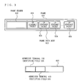
- the format of frames transmitted or received in the network 101 is the same as that in the first embodiment, and thus FIG. 3 is incorporated in this embodiment.
- the terminal 1000 performs a multiple carrier transmission by DMT in the network 101 as in the first embodiment.
- the terminal 1000 includes a transmission/reception section 2001, a data storage section 2002, an external interface section 2003, a control unit 2004, a timer section 2005, a transfer management section 2006, and a band reservation management section 2007, and further includes an IPL3 layer processing section 2008 and an application processing section 2009.
- the transmission/reception section 2001 through the transfer management section 2006 have substantially the same functions as those of the transmission/reception section 201 through the transfer management section 206 shown in FIG. 2 , respectively.
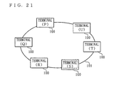
- FIG. 21 shows a structure of a network connected to the terminal shown in FIG. 20 .
- the terminal 1000 is connected to an upper layer of the network hierarchy via the external interface section 2003.
- FIG. 21 does not apparently show the elements corresponding to the network 103 and the hosts 111, etc. shown in FIG. 1 .
- the terminal 1000 realizes the functions of the network 103 and the hosts shown in FIG. 1 by the IPL3 layer processing section 2008 and the application processing section 2009. Namely, in this embodiment, the network 103 and the hosts in the first embodiment are mounted on the terminal 1000.
- the terminal 1000 can construct the network 101 even when being used together with the terminal according to the first embodiment.
- An terminal (S) shown in FIG. 21 acts as an authentication terminal.
- the network 101 constructed by the terminal 1000 only a terminal which requested the terminal (S) for an authentication and obtained such an authentication can join the network 101.
- the terminal (S) constructs the network 101 by authenticating the terminal 1000
- the terminal (S) can grasp all the terminals 1000 participated in the network 101.
- the terminal (S) will be referred to as the "authenticating terminal”.
- the authenticating terminal grasps all the terminals 1000 participated in the network 101.
- the authenticating terminal is a terminal having the same structure as that of the terminals 1000, but operates as an authenticating terminal by changing the software to be used.
- the application processing section 2009 of the terminal 1000 requests the IPL3 layer processing section 2008 to issue a broadcast packet or a multicast packet.
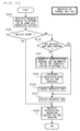
- FIG. 22 is a flowchart illustrating the details of the processing performed by the control unit 2004 shown in FIG. 20 .
- step S2101 when the external interface section 2003 receives a request to issue a packet from the application processing section 2009, the control unit 2004 performs the following processing.
- step S2102 the control unit 2004 determines whether the received packet is a unicast packet or not. When the received packet is a unicast packet, the control unit 2004 advances to step S2108. Otherwise, the control unit 2004 advances to step S2103.
- the processing in step S2101 may be performed by the external interface section 2003.
- step S2105 the control unit 2004 performs transmission path estimation on all the terminals 1000 participated in the network 101 and thus creates transmission maps on the transmission paths to all the addressee terminals.
- the transmission maps created by the control unit 2004 in step S2105 are substantially the same as those shown in FIG. 5 and will not be described here.
- step S2106 the control unit 2004 creates a multiple access map using all the transmission maps created in step S2105.
- the control unit 2004 creates the multiple access maps using the method described in the first embodiment. For example, the control unit 2004 creates the multiple access map to all the terminals 1000 in the network 101 in accordance with the control processing shown in FIG. 11 , and advances to step S2107.
- step S2107 the control unit 2004 applies the created multiple access map and advances to the processing in step S2108.
- step S2108 the control unit 2004 requests the transmission/reception section 201 to transfer a packet.
- the same multiple access map is applied regardless of whether the packet to be transmitted is a multicast packet or a broadcast packet.
- the transmission/reception section 201 may have a function of monitoring the transmission state of the frames to be issued to the network 101, using the packet re-transmission rate, the error correction rate or the like.
- the transmission/reception section 201 compares the packet re-transmission rate or the error correction rate and a predetermined threshold value or a predetermined range. When the packet re-transmission rate or the error correction rate exceeds the predetermined threshold value or the predetermined range, the transmission/reception section 201 determines that the multiple access map is not suitable and notifies this determination to the control unit 2004.
- the control unit 2004 may change the multiple access map. For example, when receiving a notification that the re-transmission rate has exceeded the threshold value from the transmission/reception section 201, the control unit 2004 decreases the number of units of described information in each sub carrier in the multiple access map. When receiving a notification that the re-transmission rate is lower than the predetermined range, the control unit 2004 increases the number of units of information to be described for each sub carrier in the multiple access map.
- control unit 2004 changing the multiple access map in accordance with the packet re-transmission rate, the error correction rate or the like, packets can always be transmitted in a manner suitable to the state of the transmission path.
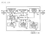
- FIG. 23 shows a structure of a terminal T100 according to a fourth embodiment of the present invention.
- the terminal T100 according to this embodiment includes a zero cross detection control unit 2401 in addition to the elements of the terminal according to the first embodiment.
- the format of frames used by the terminal T100 for data transmission in the network 101 is the same as that in the first embodiment, and thus FIG. 3 is incorporated in this embodiment.
- the terminal T100 performs a multiple carrier transmission by DMT in the network 101 as in the first embodiment.
- noise of a short cycle is generated in synchronization with the power source cycle of the electric light wire by the influence of electric/electronic household appliances having a thyristor or the like.
- the noise generated in the electric light wire has a serious influence on the transmission capability thereof. It has been found that the noise in the electric light wire is generated at a half cycle of the power source cycle of the electric light wire.
- the zero cross detection control section 2401 detects zero crossing points shown in FIG. 24 using the transmission/reception section 201 and the timer section 205 in the case where an electric light wire is used in the network 101.
- the zero cross detection control section 2401 actually measures, or virtually detects, the zero crossing points and notifies the control unit 204 of the timing at which the zero crossing points were detected.
- the control unit 204 can grasp the power source synchronization period by the timing notified from the zero cross detection control section 2401.
- FIG. 24 illustrates the zero crossing points of the supply voltage and the power source synchronization period of an electric light wire.
- FIG. 24 shows power source synchronization periods 1 through 4 (2503 through 2506) obtained as a result of dividing the half cycle of the supply voltage into four.
- the control unit 204 determines whether the power source cycle is 50 Hz or 60 Hz using the timer section 205 and thus calculates the time of the half cycle of the supply voltage.
- the power source synchronization periods are defined as obtained by equally dividing the half cycle of the supply voltage into four, but the definition of the power source synchronization periods are not limited to this.
- the power source synchronization periods do not need to be equal to one another.
- the terminal T100 performs transmission path estimation in all the power source synchronization periods, and thus records and manages all the transmission maps for each of all the power source synchronization periods.
- the terminal T100 performs the transmission path estimation for each of the zone of the power source synchronization period 1 (2503), the zone of the power source synchronization period 2 (2504), the zone of the power source synchronization period 3 (2505) and the zone of the power source synchronization period 4 (2506).
- the terminal T100 records the transmission map obtained in each power source synchronization period in the data storage section 202 , and the control unit 204 manages the recorded transmission maps.
- the terminal T100 for transmitting a packet and the terminal T100 for receiving the packet can switch the transmission map in accordance with the power source synchronization period.
- the terminal T100 can apply a transmission map in consideration of the noise in synchronization with the power source synchronization period in the electric light wire, and thus makes an effective use of the transmission capability of the electric light wire.
- the terminal T100 prepares the multiple access maps for broadcast and multicast by the same number as that of the power source synchronization periods for each unit of transmission information 423.
- the terminal T100 can make an effective use of the electric light wire network in which the noise in synchronization with the power source cycle exists.
- FIG. 25 is a schematic view showing a structure of an entire system when the present invention is applied to electric light wire communication.
- the system shown in FIG. 25 uses an electric light wire 3b as a communication medium.
- Each terminal 100 includes an outlet 100a.
- the outlet 100a is connected to a power supply section (not shown) and the transmission/reception section 201 of the terminal 100.
- the terminal 100 receives the power and also exchanges data via the outlet 100a.
- the electric light wire 3b is connected to a commercial power source 2a outside the house via an ammeter breaker 2b.
- the terminal 100 is connected to a PC, a DVD, a digital TV (DTV), a hub and the like.
- FIG. 26 is a flowchart illustrating the details of the processing of the terminal T100 of transferring a multicast packet received from the network 103.
- the external interface section 203 refers to the header information of the received packet.
- the control unit 204 performs the following processing in accordance with the flowchart shown in FIG. 26 .
- step S2201 the control unit 204 receives a request from the network 103 to transfer an IP multicast packet.
- step S2202 when the multicast packet received from the network 103 is an IGMP (or MLD) protocol JOIN or REPORT message, the control unit 204 advances to step S2208. Otherwise, the control unit 204 advances to step S2203.
- IGMP or MLD protocol
- step S2204 when the transfer permission/rejection flag 703 in the group management information 701 of the received multicast packet is "reject", the control unit 204 advances to step S2210. Otherwise, the control unit 204 advances to step S2205.
- step S2205 when the multicast address group transfer policy 705 is valid, the control unit 204 advances to step S2211. Otherwise, the control unit 204 advances to step S2206.
- step S2206 the control unit 204 accesses the timer section 205 and stops a multicast packet timer.
- the multicast packet timer uniquely corresponds to the group management information 701 by recording a timer identifier thereof in the group management information 701.
- the control unit 204 advances to step S2207 without performing the processing in step S2206.
- the control unit 204 may update the transmission information 423 by performing transmission path estimation on the link information described in all the transmission information 423 registered.
- step S2207 the control unit 204 sets the multicast address group transfer policy 705 again.
- the processing of the control unit 204 in step S2202 of setting the multicast address group transfer policy 705 is substantially the same as that of FIG. 10A through FIG. 10E .
- the control unit 204 advances to step S2211.
- step S2211 the control unit 204 applies the multicast address group transfer policy 705 which is set in the group management information 701, and advances to step S2209.
- step S2209 the control unit 204 requests the transmission/reception section 201 to transfer the received multicast packet.
- the external interface section 203 refers to the header information of the packet to determine whether the packet is a multicast packet or not.
- FIG. 27 shows the processing of the terminal T100 of transferring a multicast packet received from the network 101.
- step S2304 the control unit 204 determines whether the group management information 701 corresponding to the multicast address group of the received multicast packet is existent or not. When the group management information 701 is existent, the control unit 204 advances to step S2305; whereas when the group management information 701 is not existent, the control unit 204 advances to step S2310.
- step S2305 the control unit 204 sets the transfer policy setting 721 of the group management information 701 corresponding to the multicast address group of the received multicast packet to invalid.
- step S2308 the control unit 204 requests the external interface section 203 to transfer the received multicast packet.
- step S2310 the control unit 204 creates the group management information 701 corresponding to the multicast address group of the received multicast packet.
- step S2311 the control unit 204 applies the multicast address group transfer policy 705 of the IGMP (MLD) message.
- the processing performed by the control unit 204 in step S2311 is the same as that in step S507 in FIG. 9 .
- control unit 204 sets the transfer permission/rejection flag 703 to "permit”, the transfer policy setting 721 to "no", and the number 722 of the temporary maps to "0".
- the processing of the terminal according to this embodiment will be specifically described. It is assumed that the terminal according to this embodiment is used as each of the terminals (A) through (F) shown in FIG. 1 . In more detail, the processing of the terminals (A) and (D) when the host 116 requests for the data distributed by the host 111 will be described with reference to FIG 26 and FIG. 27 .
- Processing of the terminal (D)> the host 116 requests for an IP multicast packet of a multicast group P.
- the host 116 issues an IGMP JOIN message MP, addressed to a multicast group address PA, to the network 103.
- the control unit 204 of the terminal (D) starts the processing shown in FIG. 26 .
- step S2202 the control unit 204 of the terminal (D) determines that the received multicast packet is the IGMP JOIN message MP, and advances to the processing in step S2208.
- the control unit 204 transfers the received IGMP JOIN message MP by broadcast of the diversity mode to the network 101.
- Processing of the terminal (A)> The IGMP JOIN message MP transferred by the terminal (D) reaches the terminal (A). Upon receipt of the IGMP JOIN message MP, the control unit 204 of the terminal (A) starts the processing shown in FIG. 27 .
- step S2302 the control unit 204 of the terminal (A) determines that the received multicast packet is an IGMP JOIN message and advances to step S2303.
- step S2303 the control unit 204 determines that received multicast packet is an IGMP JOIN message and advances to step S2304.
- step S2304 the control unit 204 determines that the group management information 701 of the multicast address group PA is not existent and advances to step S2310.
- step S2310 the control unit 204 creates the group management information 701 of the multicast address group PA. After creating the group management information 701 of the multicast address group PA, the control unit 204 advances to step S2306.
- step S2306 the control unit 204 sets link information on a link connecting the terminals (A) and (D).
- the control unit 204 of the terminal (A) performs transmission path estimation on the link connecting the terminals (A) and (D), and also sets "1" for the number 722 of the registered temporarymaps and thus updates the transmission information 423.
- step S2307 the control unit 204 starts a multicast packet wait timer corresponding to the group management information 701 of the multicast address group PA and transfers the IGMP JOIN message MP to the network 103.
- the IGMP JOIN message MP transferred by the control unit 204 is received by the host 111.
- the host 111 receives the IGMP JOIN message MP of the multicast address group PA which was transferred by the terminal (A), and issues a multicast packet of the multicast address group PA to the network 103.
- the control unit 204 of the terminal (A) starts the processing shown in FIG. 26 .
- step S2202 the control unit 204 determines that the received multicast packet is not an IGMP message and advances to step S2203.
- step S2203 the control unit 204 determines that the group management information 701 of the multicast address group PA has been created and advances to step S2204.
- step S2204 the control unit 204 determines that the transfer permission/rejection flag 703 is "permit” and advances to the processing in step S2205.
- step S2205 the control unit 204 determines that the transfer policy setting 721 of the multicast address group PA is "invalid" and advances to step S2206.
- step S2206 the control unit 204 stops the multicast packet wait timer of the group management information 701.
- the control unit 204 of the terminal (A) has performed the transmission path estimation on the link connecting the terminals (A) and (D) in step S2306 shown in FIG. 27 , and thus does not perform transmission path estimation in step S2206.
- the control unit 204 transfers a multicast packet PA which is issued after the multicast packet PD to the network 101 in accordance with the processing shown in FIG. 26 as in the case of transferring the multicast packet PD.
- processing of the control unit 204 of transferring the multicast packet PA is different from the processing of the control unit 204 of transferring the multicast packet PD in the following point.
- the transfer policy setting 721 indicates "valid". Based on this, the control unit 204 applies the multicast address group transfer policy 705 of the multicast address group PA, which has been set, as it is and transfers the multicast packet PA to the network 101.
- the control unit 204 of the terminal (D) Upon receipt of the multicast packet of the multicast address group PA transferred by the terminal (A), the control unit 204 of the terminal (D) performs the processing shown in FIG. 27 .
- step S2302 the control unit 204 determines that the received multicast packet is not an IGMP message and advances to step S2308.
- step S2308 the control unit 204 transfers the receivedmulticast packet to the network 103.
- the multicast packet transferred by the terminal (D) reaches the host 116.
- control unit 204 Upon receipt of the IGMP JOIN message MP, the control unit 204 starts the processing shown in FIG. 27 .
- the control unit 204 performs the processing in steps S2301 through S2307 shown in FIG. 27 as in the case where the terminal (A) receives the IGMP JOIN message MP.
- the control unit 204 performs the processing in steps S2301 through S2307 to create the group management information 701 of the multicast address group PA and starts a multicast packet wait timer.
- the terminal (B) is connected to the host 112.
- the host 112 is not a server for distributing a multicast packet of the multicast address group PA, and so does not issue a multicast packet of the multicast address group PA.
- the control unit 204 of the terminal (B) discards the group management information 701 of the multicast address group PA.
- a terminal T100 connected to the network 101 can make an effective use of the network 101, by the control unit 204 of the terminal T100 performing the processing shown in FIG. 26 and FIG. 27 .
- the term "recording medium” refers to an assembly of semiconductor elements such as a ROM, a RAM, a flash memory or the like; a magnetic disc memory such as a flexible disc, a hard disc or the like; an optical disc such as a CD-ROM disc, a DVD disc, a BD (Blu-Ray (registered trademark) disc) or the like; a memory card; or the like.
- the invention disclosed by the present application is applicable to, for example, networks in general houses and apartment buildings; networks in business facilities including business offices, plants and commercial facilities; networks such as avionics systems which are constructed in transportation facilities including automobiles, aircraft, railway trains and watercraft; and the like.
- networks in general houses and apartment buildings including business offices, plants and commercial facilities
- networks such as avionics systems which are constructed in transportation facilities including automobiles, aircraft, railway trains and watercraft; and the like.
- efficient multiple access transmission is made possible by the technology of the present invention.
- the group management protocol mounted on the terminal is an IGMP protocol or an MLD protocol.
- the group management protocol mounted on a terminal is not limited to these, and any other group management protocol capable of managing a group is usable, needless to say.
- the present invention is useful, for example, as a terminal realizing a fast and high quality packet transmission in a network using IP multicast.
Landscapes
- Engineering & Computer Science (AREA)
- Computer Networks & Wireless Communication (AREA)
- Signal Processing (AREA)
- Data Exchanges In Wide-Area Networks (AREA)
- Small-Scale Networks (AREA)
Applications Claiming Priority (2)
| Application Number | Priority Date | Filing Date | Title |
|---|---|---|---|
| JP2006073365 | 2006-03-16 | ||
| PCT/JP2007/055425 WO2007119403A1 (fr) | 2006-03-16 | 2007-03-16 | Terminal |
Publications (3)
| Publication Number | Publication Date |
|---|---|
| EP1993243A1 true EP1993243A1 (fr) | 2008-11-19 |
| EP1993243A4 EP1993243A4 (fr) | 2011-04-13 |
| EP1993243B1 EP1993243B1 (fr) | 2012-06-06 |
Family
ID=38609194
Family Applications (1)
| Application Number | Title | Priority Date | Filing Date |
|---|---|---|---|
| EP20070738870 Active EP1993243B1 (fr) | 2006-03-16 | 2007-03-16 | Terminal |
Country Status (6)
| Country | Link |
|---|---|
| US (1) | US7978698B2 (fr) |
| EP (1) | EP1993243B1 (fr) |
| JP (1) | JP4791533B2 (fr) |
| KR (1) | KR20090006828A (fr) |
| CN (1) | CN101401375B (fr) |
| WO (1) | WO2007119403A1 (fr) |
Families Citing this family (18)
| Publication number | Priority date | Publication date | Assignee | Title |
|---|---|---|---|---|
| DE102006024707B3 (de) * | 2006-05-26 | 2007-07-12 | Siemens Ag | Verfahren und Anordnung zum Aufbau von Kommunikationsbeziehungen |
| US7953895B1 (en) * | 2007-03-07 | 2011-05-31 | Juniper Networks, Inc. | Application identification |
| US20080240096A1 (en) | 2007-03-29 | 2008-10-02 | Twisted Pair Solutions, Inc. | Method, apparatus, system, and article of manufacture for providing distributed convergence nodes in a communication network environment |
| US9712787B2 (en) * | 2007-07-02 | 2017-07-18 | At&T Intellectual Property I, L.P. | System and method of delivering video content |
| WO2010002844A2 (fr) | 2008-07-01 | 2010-01-07 | Twisted Pair Solutions, Inc. | Méthode, appareil, système et article manufacturé fournissant des informations fiables sur faible largeur de bande via des réseaux uni et multidiffusion en mode mixte |
| US8902805B2 (en) * | 2008-10-24 | 2014-12-02 | Qualcomm Incorporated | Cell relay packet routing |
| US8018934B2 (en) * | 2009-03-20 | 2011-09-13 | Cisco Technology, Inc. | Switched unicast in an internet protocol television environment |
| CN101515889B (zh) * | 2009-04-03 | 2011-07-06 | 华为技术有限公司 | 一种组播报文的复制处理方法和装置 |
| US8391240B2 (en) * | 2009-12-29 | 2013-03-05 | Symbol Technologies, Inc. | Updating an IGMP membership report when a wireless client device roams across IP subnets |
| TW201134284A (en) * | 2010-03-29 | 2011-10-01 | Gemtek Technology Co Ltd | Streaming data relay apparatus and related wireless gateway apparatus |
| JP5672779B2 (ja) * | 2010-06-08 | 2015-02-18 | ソニー株式会社 | 送信制御装置、および送信制御方法 |
| KR101677638B1 (ko) | 2010-09-29 | 2016-11-18 | 엘지전자 주식회사 | 이동 단말기 및 그 제어 방법 |
| KR20120139574A (ko) * | 2011-06-17 | 2012-12-27 | 삼성전자주식회사 | UPnP 기반 디바이스 간 데이터 교환 장치 및 방법 |
| US9306836B2 (en) * | 2012-07-30 | 2016-04-05 | Hewlett Packard Enterprise Development Lp | Searching for multicast consumers in a network of interconnected nodes |
| JP6281566B2 (ja) * | 2013-04-05 | 2018-02-21 | ソニー株式会社 | 中継管理装置、中継管理方法、プログラムおよび中継管理システム |
| WO2017183278A1 (fr) | 2016-04-18 | 2017-10-26 | ソニー株式会社 | Appareil de communication, procédé de communication et programme |
| WO2023139914A1 (fr) * | 2022-01-24 | 2023-07-27 | 住友電気工業株式会社 | Dispositif embarqué, dispositif de gestion, système d'authentification de chemin de transmission, procédé d'authentification de chemin de transmission et procédé de gestion |
| JP2023131231A (ja) * | 2022-03-09 | 2023-09-22 | 日本電気株式会社 | 通信システム、通信装置、通信方法及び通信プログラム |
Family Cites Families (96)
| Publication number | Priority date | Publication date | Assignee | Title |
|---|---|---|---|---|
| US4531822A (en) * | 1978-12-01 | 1985-07-30 | Polaroid Corporation | Extended sonic acceptance angle |
| US4473285A (en) * | 1981-11-27 | 1984-09-25 | W. Haking Enterprises Limited | Automatic focusing camera |
| US4490814A (en) * | 1982-09-30 | 1984-12-25 | Polaroid Corporation | Sonic autofocus camera having variable sonic beamwidth |
| US4980671A (en) * | 1989-04-26 | 1990-12-25 | Guardian Technologies, Inc. | Remote confinement system with timed tamper signal reset |
| US5778304A (en) * | 1994-03-10 | 1998-07-07 | Motorola, Inc. | Method for providing communication services based on geographic location |
| US6049273A (en) * | 1994-09-09 | 2000-04-11 | Tattletale Portable Alarm, Inc. | Cordless remote alarm transmission apparatus |
| US6028626A (en) * | 1995-01-03 | 2000-02-22 | Arc Incorporated | Abnormality detection and surveillance system |
| JPH0933791A (ja) * | 1995-07-21 | 1997-02-07 | Sony Corp | レンズ駆動装置及び撮像装置 |
| US6208379B1 (en) * | 1996-02-20 | 2001-03-27 | Canon Kabushiki Kaisha | Camera display control and monitoring system |
| US5848161A (en) * | 1996-05-16 | 1998-12-08 | Luneau; Greg | Method for providing secured commerical transactions via a networked communications system |
| US6195772B1 (en) * | 1996-06-21 | 2001-02-27 | Altera Corporaiton | Electronic circuit testing methods and apparatus |
| US6018374A (en) * | 1996-06-25 | 2000-01-25 | Macrovision Corporation | Method and system for preventing the off screen copying of a video or film presentation |
| US7159116B2 (en) * | 1999-12-07 | 2007-01-02 | Blue Spike, Inc. | Systems, methods and devices for trusted transactions |
| US5790074A (en) * | 1996-08-15 | 1998-08-04 | Ericsson, Inc. | Automated location verification and authorization system for electronic devices |
| SK22499A3 (en) * | 1996-08-23 | 1999-10-08 | Cook Biotech Inc | Graft prosthesis, materials and methods |
| JPH10299613A (ja) | 1997-04-25 | 1998-11-10 | Denso Corp | 燃料噴射弁 |
| DE69834218T2 (de) * | 1997-05-13 | 2007-01-04 | Kabushiki Kaisha Toshiba, Kawasaki | Informationsaufzeichnungs- und -wiedergabegerät sowie Informationsverteilungssystem |
| US5960081A (en) * | 1997-06-05 | 1999-09-28 | Cray Research, Inc. | Embedding a digital signature in a video sequence |
| JP2965007B2 (ja) * | 1997-08-11 | 1999-10-18 | 日本電気株式会社 | 携帯電話システム |
| US6343213B1 (en) * | 1997-10-24 | 2002-01-29 | Nortel Networks Limited | Method to protect against interference from mobile radios |
| JPH11225163A (ja) | 1998-02-05 | 1999-08-17 | Nippon Telegr & Teleph Corp <Ntt> | Ipマルチキャスト通信方法及びこれに用いるダイアルアップアクセスサーバ |
| ES2138557B1 (es) * | 1998-02-26 | 2000-08-16 | Carballo Jose Maria Pousada | Enmascarador de llamadas para telefonia movil. |
| US6189146B1 (en) * | 1998-03-18 | 2001-02-13 | Microsoft Corporation | System and method for software licensing |
| US6111364A (en) * | 1998-04-10 | 2000-08-29 | Davis; Jerry L. | Method and device to inhibit the flash photography of a vehicle |
| JP3252825B2 (ja) * | 1998-04-17 | 2002-02-04 | 日本電気株式会社 | 携帯電話における自動電波出力制限システム |
| US6529600B1 (en) * | 1998-06-25 | 2003-03-04 | Koninklijke Philips Electronics N.V. | Method and device for preventing piracy of video material from theater screens |
| JP2938062B1 (ja) * | 1998-09-01 | 1999-08-23 | 埼玉日本電気株式会社 | 移動無線通信機 |
| JP3519616B2 (ja) | 1998-10-21 | 2004-04-19 | 株式会社日立製作所 | 中継装置 |
| US7324133B2 (en) * | 1998-11-06 | 2008-01-29 | Fotomedia Technologies, Llc | Method and apparatus for controlled camera useability |
| US6321338B1 (en) * | 1998-11-09 | 2001-11-20 | Sri International | Network surveillance |
| TW527491B (en) * | 1999-02-02 | 2003-04-11 | Fujitsu Ltd | Test method and test circuit for electronic device |
| US6677858B1 (en) * | 1999-02-26 | 2004-01-13 | Reveo, Inc. | Internet-based method of and system for monitoring space-time coordinate information and biophysiological state information collected from an animate object along a course through the space-time continuum |
| US7035666B2 (en) * | 1999-06-09 | 2006-04-25 | Shimon Silberfening | Combination cellular telephone, sound storage device, and email communication device |
| JP2001111518A (ja) | 1999-10-04 | 2001-04-20 | Mitsubishi Electric Corp | 通信方法および通信装置 |
| US6424370B1 (en) * | 1999-10-08 | 2002-07-23 | Texas Instruments Incorporated | Motion based event detection system and method |
| US7120692B2 (en) * | 1999-12-02 | 2006-10-10 | Senvid, Inc. | Access and control system for network-enabled devices |
| US20010031631A1 (en) * | 2000-01-12 | 2001-10-18 | Pitts Robert L. | Secure area communication arrester |
| US6687497B1 (en) * | 2000-02-11 | 2004-02-03 | Sony Electronics Inc. | Method, system, and structure for disabling a communication device during the occurrence of one or more predetermined conditions |
| US6640098B1 (en) * | 2000-02-14 | 2003-10-28 | Action Engine Corporation | System for obtaining service-related information for local interactive wireless devices |
| US7457628B2 (en) * | 2000-02-29 | 2008-11-25 | Smarter Agent, Llc | System and method for providing information based on geographic position |
| GB0012445D0 (en) * | 2000-05-24 | 2000-07-12 | Hewlett Packard Co | Location-based equipment control |
| GB2363504A (en) * | 2000-06-16 | 2001-12-19 | Nokia Mobile Phones Ltd | A mobile phone including a device for preventing loss or theft |
| US6662023B1 (en) * | 2000-07-06 | 2003-12-09 | Nokia Mobile Phones Ltd. | Method and apparatus for controlling and securing mobile phones that are lost, stolen or misused |
| US7382397B2 (en) * | 2000-07-26 | 2008-06-03 | Smiths Detection, Inc. | Systems and methods for controlling devices over a network |
| US6771946B1 (en) * | 2000-07-31 | 2004-08-03 | Michael F. Oyaski | Method of preventing cell phone use while vehicle is in motion |
| JP4078022B2 (ja) * | 2000-09-06 | 2008-04-23 | 株式会社エヌ・ティ・ティ・ドコモ | ゲートウェイサーバ及び情報提供方法 |
| AU2001290822A1 (en) * | 2000-09-11 | 2002-03-26 | Digimarc Corporation | Authenticating and measuring quality of service of multimedia signals using digital watermark analyses |
| US20020194361A1 (en) | 2000-09-22 | 2002-12-19 | Tomoaki Itoh | Data transmitting/receiving method, transmitting device, receiving device, transmiting/receiving system, and program |
| US6559883B1 (en) * | 2000-09-27 | 2003-05-06 | David H. Sitrick | Movie film security system utilizing infrared patterns |
| GB2367720B (en) * | 2000-10-04 | 2004-08-18 | Hewlett Packard Co | Method and apparatus for disabling mobile telephones |
| TW546874B (en) * | 2000-10-11 | 2003-08-11 | Sony Corp | Robot apparatus and its control method with a function of preventing an image from being stolen |
| US7099699B2 (en) * | 2000-11-14 | 2006-08-29 | Lg Electronics Inc. | Method for preventing illegal use of mobile communication terminal |
| US20030149973A1 (en) * | 2000-12-20 | 2003-08-07 | Jan Kerlefsen | Information processing method and device, recording medium, and program |
| KR100467643B1 (ko) * | 2000-12-28 | 2005-01-24 | 엘지전자 주식회사 | 무선 랜에서의 멀티미디어 데이터 전송 방법 |
| EP1352523B1 (fr) * | 2001-01-16 | 2004-08-04 | Nagracard S.A. | Methode pour stocker des donnees encryptees |
| GB2371907A (en) * | 2001-02-03 | 2002-08-07 | Hewlett Packard Co | Controlling the use of portable cameras |
| US6799052B2 (en) * | 2001-02-08 | 2004-09-28 | Michael K. Agness | Hand-held cellular telephone system with location transmission inhibit |
| US6396399B1 (en) * | 2001-03-05 | 2002-05-28 | Hewlett-Packard Company | Reduction of devices to quiet operation |
| US6353778B1 (en) * | 2001-03-15 | 2002-03-05 | International Business Machines Corporation | Automobile computer control system for limiting the usage of wireless telephones on moving automobiles |
| JP3988476B2 (ja) * | 2001-03-23 | 2007-10-10 | セイコーエプソン株式会社 | 座標入力装置及び表示装置 |
| US20030037237A1 (en) * | 2001-04-09 | 2003-02-20 | Jean-Paul Abgrall | Systems and methods for computer device authentication |
| US20020191102A1 (en) * | 2001-05-31 | 2002-12-19 | Casio Computer Co., Ltd. | Light emitting device, camera with light emitting device, and image pickup method |
| US20020186845A1 (en) * | 2001-06-11 | 2002-12-12 | Santanu Dutta | Method and apparatus for remotely disabling and enabling access to secure transaction functions of a mobile terminal |
| US7339903B2 (en) * | 2001-06-14 | 2008-03-04 | Qualcomm Incorporated | Enabling foreign network multicasting for a roaming mobile node, in a foreign network, using a persistent address |
| EP1276320B1 (fr) * | 2001-06-15 | 2015-05-27 | L-1 Identity Solutions AG | Méthode pour rendre inidentifiable et pour restorer le contenu d'une image |
| US6868229B2 (en) * | 2001-09-20 | 2005-03-15 | Intel Corporation | Interfering with illicit recording activity by emitting non-visible radiation |
| DE60218498T2 (de) * | 2001-09-20 | 2007-11-08 | Koninklijke Philips Electronics N.V. | Elektronisches gerät |
| JP2003101504A (ja) | 2001-09-21 | 2003-04-04 | Sony Corp | 送信装置および方法、通信システム、記録媒体、並びにプログラム |
| US7181229B2 (en) * | 2001-09-25 | 2007-02-20 | Yash Pal Singh | System which automatically disables or switches off a cellphone |
| WO2003033998A1 (fr) * | 2001-10-16 | 2003-04-24 | Matsushita Electric Industrial Co., Ltd. | Terminal |
| ATE313193T1 (de) * | 2001-10-31 | 2005-12-15 | Nokia Corp | Eine methode für handhabung von meldungen zwischen einem terminal und einem datennetz |
| JP3875086B2 (ja) * | 2001-11-30 | 2007-01-31 | ソフトバンクテレコム株式会社 | 直交周波数分割多重システムおよび送受信装置 |
| US7382405B2 (en) * | 2001-12-03 | 2008-06-03 | Nikon Corporation | Electronic apparatus having a user identification function and user identification method |
| JP4338924B2 (ja) * | 2001-12-05 | 2009-10-07 | 株式会社エヌ・ティ・ティ・ドコモ | マルチキャスト通信方式、マルチキャスト通信に用いる中継ノード装置、及び、中継ノード装置における送信制御方法 |
| US7392394B2 (en) * | 2001-12-13 | 2008-06-24 | Digimarc Corporation | Digital watermarking with variable orientation and protocols |
| US20030132880A1 (en) * | 2002-01-14 | 2003-07-17 | Hintz Kenneth James | Precision position measurement system |
| US7080405B2 (en) * | 2002-01-16 | 2006-07-18 | International Business Machines Corporation | Limiting device function |
| JP2003215440A (ja) * | 2002-01-24 | 2003-07-30 | Casio Comput Co Ltd | オートフォーカス方法、及びオートフォーカス装置 |
| US7050796B2 (en) * | 2002-01-25 | 2006-05-23 | International Business Machines Corporation | Method of controlling the auditory response of wireless devices |
| US6658091B1 (en) * | 2002-02-01 | 2003-12-02 | @Security Broadband Corp. | LIfestyle multimedia security system |
| US7054624B2 (en) * | 2002-04-02 | 2006-05-30 | X-Cyte, Inc. | Safeguarding user data stored in mobile communications devices |
| GB0211612D0 (en) * | 2002-05-21 | 2002-07-03 | Eastman Kodak Co | A method and system for the prevention of copyright piracy |
| US20030233410A1 (en) * | 2002-06-06 | 2003-12-18 | International Business Machines Corporation | Electronic carbon copy dissemination control |
| AU2003262848A1 (en) * | 2002-08-21 | 2004-03-11 | Zyray Wireless, Inc. | Antenna array including virtual antenna elements |
| ATE347212T1 (de) * | 2002-09-10 | 2006-12-15 | Koninkl Philips Electronics Nv | Echtzeit - neuversuchsgrenze ein system und verfahren zur maximierung des durchsatzes und zur minimierung von paketverlusten drahtloser lokaler netzwerke |
| US6922524B2 (en) * | 2002-11-27 | 2005-07-26 | Olympus Corporation | Camera having blur detecting function |
| TW200410557A (en) * | 2002-12-13 | 2004-06-16 | Lite On Technology Corp | Method for making inquiry about location of cellular phone user |
| TWI237491B (en) * | 2002-12-13 | 2005-08-01 | Lite On Technology Corp | Method for displaying location of cellular phone caller |
| JP4396245B2 (ja) * | 2003-02-04 | 2010-01-13 | 日本電気株式会社 | 撮影機能付き移動通信端末の動作制限システム及び撮影機能付き移動通信端末 |
| US20070129012A1 (en) * | 2003-04-01 | 2007-06-07 | Iceberg Systems Limited | Portable digital devices |
| US7006630B2 (en) * | 2003-06-03 | 2006-02-28 | Matsushita Electric Industrial Co., Ltd. | Methods and apparatus for digital content protection |
| JP4508753B2 (ja) * | 2003-07-12 | 2010-07-21 | エルジー エレクトロニクス インコーポレイティド | 携帯端末機のカメラ撮影制限システム及びその方法 |
| US20050043548A1 (en) * | 2003-08-22 | 2005-02-24 | Joseph Cates | Automated monitoring and control system for networked communications |
| EP1536391A1 (fr) * | 2003-11-28 | 2005-06-01 | Connexion2 Limited | Moniteur pour travailleurs isolés |
| US7190808B2 (en) * | 2004-03-12 | 2007-03-13 | Interdigital Technology Corporation | Method for watermarking recordings based on atmospheric conditions |
| US7272240B2 (en) * | 2004-12-03 | 2007-09-18 | Interdigital Technology Corporation | Method and apparatus for generating, sensing, and adjusting watermarks |
-
2007
- 2007-03-16 US US12/282,947 patent/US7978698B2/en active Active
- 2007-03-16 JP JP2008510802A patent/JP4791533B2/ja not_active Expired - Fee Related
- 2007-03-16 EP EP20070738870 patent/EP1993243B1/fr active Active
- 2007-03-16 WO PCT/JP2007/055425 patent/WO2007119403A1/fr not_active Ceased
- 2007-03-16 CN CN2007800089761A patent/CN101401375B/zh active Active
- 2007-03-16 KR KR20087024865A patent/KR20090006828A/ko not_active Withdrawn
Non-Patent Citations (2)
| Title |
|---|
| JIA W ET AL: "Integrated fault-tolerant multicast and anycast routing algorithms", IEE PROCEEDINGS E. COMPUTERS & DIGITAL TECHNIQUES, INSTITUTION OF ELECTRICAL ENGINEERS. STEVENAGE, GB, vol. 147, no. 4, 28 July 2000 (2000-07-28) , pages 266-274, XP006013916, ISSN: 0143-7062, DOI: DOI:10.1049/IP-CDT:20000532 * |
| See also references of WO2007119403A1 * |
Also Published As
| Publication number | Publication date |
|---|---|
| JPWO2007119403A1 (ja) | 2009-08-27 |
| CN101401375B (zh) | 2012-05-09 |
| JP4791533B2 (ja) | 2011-10-12 |
| US7978698B2 (en) | 2011-07-12 |
| CN101401375A (zh) | 2009-04-01 |
| US20090257432A1 (en) | 2009-10-15 |
| WO2007119403A1 (fr) | 2007-10-25 |
| EP1993243A4 (fr) | 2011-04-13 |
| KR20090006828A (ko) | 2009-01-15 |
| EP1993243B1 (fr) | 2012-06-06 |
Similar Documents
| Publication | Publication Date | Title |
|---|---|---|
| EP1993243B1 (fr) | Terminal | |
| US20110317587A1 (en) | Methods and systems for time sensitive networks | |
| US9014051B2 (en) | Updating multicast group information of a client device of a wireless mesh network | |
| CN103999405B (zh) | 组合多个通信链路的系统和方法 | |
| CN101272324B (zh) | 服务质量控制方法及网络设备 | |
| US20090168681A1 (en) | Mechanism for wireless multicast | |
| CN104285423B (zh) | 在面向包的通讯网络中传输数据的方法和在通讯网络中相应设置的用户设备 | |
| JP2012508496A (ja) | マルチキャスト通信のためのデータ速度適合の方法 | |
| EP4084348B1 (fr) | Procédé et appareil d'attribution de créneaux temporels pour communication par courants porteurs en ligne | |
| US20150304118A1 (en) | Method for preselecting a router in an rpl network | |
| JP5485543B2 (ja) | プライマリネットワーク及びセカンダリネットワークを含むネットワークにおける通信方法 | |
| US20200137077A1 (en) | Method and apparatus for supporting sub networks in a moca network | |
| US8432847B2 (en) | VTS frame format | |
| KR20130100752A (ko) | 다수의 네트워크를 통한 데이터 스트림의 전송 관리 | |
| US8462792B2 (en) | Networks having plurality of nodes | |
| CN110856231A (zh) | 一种基于多跳网络的多数据流传输方法 | |
| CN117177106A (zh) | 一种通信方法、装置、通信设备和计算机存储介质 | |
| CN101635634B (zh) | 一种基于标识的组播管理方法与系统 | |
| US10541829B2 (en) | Network devices for scalable point to multipoint networks | |
| CN104506442A (zh) | 一种灵活网格光网络的多点到多点组播业务光疏导方法 | |
| WO2016160040A1 (fr) | Agrégation effective de paquets à l'aide de caractéristiques de canal dans un réseau de communication | |
| Yousefi et al. | Multicast scheduling algorithm supporting spatial mini-slot reuse for IEEE 802.16 mesh networks | |
| CN103812785A (zh) | 用于电力应急通信系统的空间自组网流量控制方法及系统 | |
| KR101465543B1 (ko) | 미디어서비스 중계 장치 및 미디어서비스 중계 방법 | |
| CN117749705A (zh) | 流量调度方法、交换节点、控制器和时间敏感网络 |
Legal Events
| Date | Code | Title | Description |
|---|---|---|---|
| PUAI | Public reference made under article 153(3) epc to a published international application that has entered the european phase |
Free format text: ORIGINAL CODE: 0009012 |
|
| 17P | Request for examination filed |
Effective date: 20080920 |
|
| AK | Designated contracting states |
Kind code of ref document: A1 Designated state(s): DE ES FR GB |
|
| RBV | Designated contracting states (corrected) |
Designated state(s): DE ES FR GB |
|
| A4 | Supplementary search report drawn up and despatched |
Effective date: 20110315 |
|
| RIC1 | Information provided on ipc code assigned before grant |
Ipc: H04L 12/26 20060101ALN20110309BHEP Ipc: H04L 12/18 20060101AFI20110309BHEP |
|
| REG | Reference to a national code |
Ref country code: DE Ref legal event code: R079 Ref document number: 602007023163 Country of ref document: DE Free format text: PREVIOUS MAIN CLASS: H04L0012560000 Ipc: H04L0012180000 |
|
| GRAP | Despatch of communication of intention to grant a patent |
Free format text: ORIGINAL CODE: EPIDOSNIGR1 |
|
| RIC1 | Information provided on ipc code assigned before grant |
Ipc: H04L 12/26 20060101ALN20120110BHEP Ipc: H04L 12/18 20060101AFI20120110BHEP |
|
| DAX | Request for extension of the european patent (deleted) | ||
| GRAS | Grant fee paid |
Free format text: ORIGINAL CODE: EPIDOSNIGR3 |
|
| GRAA | (expected) grant |
Free format text: ORIGINAL CODE: 0009210 |
|
| AK | Designated contracting states |
Kind code of ref document: B1 Designated state(s): DE ES FR GB |
|
| REG | Reference to a national code |
Ref country code: GB Ref legal event code: FG4D |
|
| REG | Reference to a national code |
Ref country code: DE Ref legal event code: R096 Ref document number: 602007023163 Country of ref document: DE Effective date: 20120802 |
|
| PLBE | No opposition filed within time limit |
Free format text: ORIGINAL CODE: 0009261 |
|
| STAA | Information on the status of an ep patent application or granted ep patent |
Free format text: STATUS: NO OPPOSITION FILED WITHIN TIME LIMIT |
|
| PG25 | Lapsed in a contracting state [announced via postgrant information from national office to epo] |
Ref country code: ES Free format text: LAPSE BECAUSE OF FAILURE TO SUBMIT A TRANSLATION OF THE DESCRIPTION OR TO PAY THE FEE WITHIN THE PRESCRIBED TIME-LIMIT Effective date: 20120917 |
|
| 26N | No opposition filed |
Effective date: 20130307 |
|
| REG | Reference to a national code |
Ref country code: DE Ref legal event code: R097 Ref document number: 602007023163 Country of ref document: DE Effective date: 20130307 |
|
| REG | Reference to a national code |
Ref country code: FR Ref legal event code: ST Effective date: 20131129 |
|
| PG25 | Lapsed in a contracting state [announced via postgrant information from national office to epo] |
Ref country code: FR Free format text: LAPSE BECAUSE OF NON-PAYMENT OF DUE FEES Effective date: 20130402 |
|
| PGFP | Annual fee paid to national office [announced via postgrant information from national office to epo] |
Ref country code: DE Payment date: 20250319 Year of fee payment: 19 |
|
| PGFP | Annual fee paid to national office [announced via postgrant information from national office to epo] |
Ref country code: GB Payment date: 20250319 Year of fee payment: 19 |