EP1993307B1 - System und verfahren zum senden und empfangen gemeinsamer steuerinformationen in einem drahtlosen kommunikationssystem - Google Patents
System und verfahren zum senden und empfangen gemeinsamer steuerinformationen in einem drahtlosen kommunikationssystem Download PDFInfo
- Publication number
- EP1993307B1 EP1993307B1 EP08009132.5A EP08009132A EP1993307B1 EP 1993307 B1 EP1993307 B1 EP 1993307B1 EP 08009132 A EP08009132 A EP 08009132A EP 1993307 B1 EP1993307 B1 EP 1993307B1
- Authority
- EP
- European Patent Office
- Prior art keywords
- information
- common control
- control information
- communication system
- decoding
- Prior art date
- Legal status (The legal status is an assumption and is not a legal conclusion. Google has not performed a legal analysis and makes no representation as to the accuracy of the status listed.)
- Not-in-force
Links
Images


Classifications
-
- H—ELECTRICITY
- H04—ELECTRIC COMMUNICATION TECHNIQUE
- H04W—WIRELESS COMMUNICATION NETWORKS
- H04W72/00—Local resource management
- H04W72/20—Control channels or signalling for resource management
- H04W72/23—Control channels or signalling for resource management in the downlink direction of a wireless link, i.e. towards a terminal
-
- H—ELECTRICITY
- H04—ELECTRIC COMMUNICATION TECHNIQUE
- H04W—WIRELESS COMMUNICATION NETWORKS
- H04W16/00—Network planning, e.g. coverage or traffic planning tools; Network deployment, e.g. resource partitioning or cells structures
- H04W16/14—Spectrum sharing arrangements between different networks
-
- H—ELECTRICITY
- H04—ELECTRIC COMMUNICATION TECHNIQUE
- H04W—WIRELESS COMMUNICATION NETWORKS
- H04W72/00—Local resource management
- H04W72/04—Wireless resource allocation
- H04W72/044—Wireless resource allocation based on the type of the allocated resource
- H04W72/0453—Resources in frequency domain, e.g. a carrier in FDMA
-
- H—ELECTRICITY
- H04—ELECTRIC COMMUNICATION TECHNIQUE
- H04W—WIRELESS COMMUNICATION NETWORKS
- H04W72/00—Local resource management
- H04W72/12—Wireless traffic scheduling
- H04W72/1215—Wireless traffic scheduling for collaboration of different radio technologies
-
- H—ELECTRICITY
- H04—ELECTRIC COMMUNICATION TECHNIQUE
- H04W—WIRELESS COMMUNICATION NETWORKS
- H04W76/00—Connection management
- H04W76/10—Connection setup
- H04W76/11—Allocation or use of connection identifiers
-
- H—ELECTRICITY
- H04—ELECTRIC COMMUNICATION TECHNIQUE
- H04W—WIRELESS COMMUNICATION NETWORKS
- H04W48/00—Access restriction; Network selection; Access point selection
- H04W48/08—Access restriction or access information delivery, e.g. discovery data delivery
- H04W48/12—Access restriction or access information delivery, e.g. discovery data delivery using downlink control channel
Definitions
- the present invention relates generally to a wireless communication system, and more particularly, to a method for transmitting and receiving common control information in a wireless communication system.
- wireless communication systems are being developed to support various services such as broadcasting, multimedia video, multimedia messaging, etc.
- the 4 th generation wireless communication system is being developed to provide a data rate of 100 Mbps or higher to high-speed mobile users, and a data rate of 1 Gbps or higher to low-speed mobile users, in voice and packet data communications.
- the wireless communication systems are developing from the existing communication systems into evolved communication systems.
- the existing communication system will be referred to as a 'legacy communication system'
- the evolved communication system will be referred to as a 'new communication system'.
- the new communication system intends to introduce new (evolved) technologies unused in the legacy communication system.
- the new technologies include multi-antenna technology, Internet Protocol version 6 (IPv6) technology, multicast/broadcast service technology, etc.
- the two communication systems should interwork with each other for users of the legacy communication system and users of the new communication system.
- new technical schemes for supporting the replacement should be defined, because the legacy communication system and the new communication system may have different channel structures and/or different signaling structures.
- the common control information is important information that all mobile stations existing in the system should receive. Therefore, in the case where the legacy communication system and the new communication system coexist, a transmission/reception scheme of the common control information should be defined. Even in the case where the legacy communication system is replaced with the new communication system, a transmission/reception scheme of the common control information should be newly defined.
- WO 2005/039105 discloses techniques for MAC processing for efficient use of high throughput systems that may be backward compatible with various types of legacy systems.
- a data frame is formed comprising a common portion for transmission in a format receivable by various stations, such as access points and remote stations.
- the data frame also comprises a dedicated portion, formatted for transmission to a specified remote station.
- the common portion is unsteered, and the dedicated portion is steered.
- an access point schedules an allocation in response to a data indication included in a common portion of a data frame transmitted from one remote station to another.
- a first station transmits a reference to a second station, which measures the reference and generates feedback therefrom.
- an aspect of the present invention provides a system and method for transmitting and receiving common control information caused by the development of wireless communication systems.
- a method for transmitting common control information by a base station in a wireless communication system. It is determined whether the wireless communication system is a coexistence system, in which a first system and a second system, different from the first system, coexist.
- the wireless communication system is a coexistence system
- information for coexistence of the first system and the second system, position and size information of a resource allocation zone where common control information for the second system can be transmitted, and information necessary for decoding of the resource allocation zone, through a first information element in a downlink subframe where resources are occupied for the first system, are indicated.
- the common control information of the second system is transmitted in the resource allocation zone where the common control information can be transmitted.
- a method for receiving common control information by a mobile station in a wireless communication system.
- Information on a frame structure transmitted from a base station is decoded. It is determined whether a wireless communication system is a coexistence system where a first system and a second system different from the first system coexist.
- Common control information for the first system is decoded when the wireless communication system is a coexistence system.
- Information on a position and size where common control information for the second system is transmitted, and information necessary for decoding of the common control information according to the decoding result on the common control information are acquired.
- Common control information for the second system is decoded using the acquired information.
- the present invention provides a method for transmitting and receiving common control information in a wireless communication system.
- the wireless communication system can be a system where the existing (or legacy) communication system and a new communication system evolved from the legacy communication system coexist, or a system where the legacy communication system is replaced by the new communication system.
- the term 'common control information' as used herein refers to both of the information included in a Frame Control Header (FCH) and MAP used in the legacy communication system, and the information included in a Broadcasting Channel (BCH) of the new communication system of the present invention.
- FCH Frame Control Header
- BCH Broadcasting Channel
- the legacy communication system and the new communication system can be distinguished from each other by time or frequency.
- the downlink can be divided by the time and the uplink can be divided by the frequency, and vice versa.
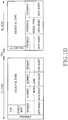
- FIGs. 1A and 1B a description will now be made of a frame structure available in the coexistence system.
- FIGs. 1A and 1B are diagrams illustrating frame structures based on Time Division Multiplexing (TDM) and Frequency Division Multiplexing (FDM), respectively.
- TDM Time Division Multiplexing
- FDM Frequency Division Multiplexing
- a frame includes a preamble used in common in the legacy communication system and the new communication system, and a downlink subframe (DL) and an uplink subframe (UL) that distinguish the legacy communication system from the new communication system by time.
- the downlink subframe is distinguished from the uplink subframe by Time Transition Gap (TTG).
- TGT Time Transition Gap
- a ratio of resources used by the legacy communication system to resources used by the new communication system in the downlink subframe 110 and the uplink subframe 120 can be fixedly determined during initial system realization depending on the number of mobile stations using the corresponding system and/or other various factors, or can be variably determined during system operation.
- the resource ratio of the downlink subframe 110 to the uplink subframe 120 can be fixedly determined during initial system realization depending on the number of mobile stations using the corresponding system and/or other various factors, or can be variably determined during system operation.
- a frame in FIG. 1B is similar in structure to the frame of FIG. 1A , but it is different in that the legacy communication system is distinguished from the new communication system by frequency.
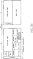
- FIG. 2 is a diagram illustrating a frame structure including BCH for a new system, to be used for a coexistence system, according to an embodiment of the present invention.
- a frame includes a FCH 201, a legacy MAP, a MAP Information Element (MAP_IE) 205, and a BCH 207.
- the mobile station acquires synchronization with a base station through a preamble, and decodes the FCH 201.
- the mobile station decodes the legacy MAP using the FCH decoding result, thereby recognizing position and size of its own data burst.
- the base station uses some bits among the reserved bits of FCH unused in the legacy system to transmit information indicating whether the corresponding frame is a frame only for the legacy communication system, a frame for the coexistence system, or a frame only for the new communication system.
- the mobile station recognizes whether the corresponding frame is a frame only for the legacy communication system, a frame for the coexistence system, or a frame only for the new communication system depending on the reserved bit value of the corresponding FCH.
- the mobile station determines whether there is any MAP IE corresponding to a previously allocated Group Connection Identifier (GCID).
- GCID Group Connection Identifier
- the GCID an arbitrary CID among the CIDs allocable to mobile stations using the legacy communication system, is a CID predefined between the base station and the new communication system.
- the base station secures it by not allocating the corresponding CID to a legacy mobile station, and the GCID is used for distinguishing a mobile station using the new communication system.
- the mobile station using the new communication system can be allocated an arbitrary CID of '1010101010' as the same GCID regardless of the base station.
- the base station can secure multiple CIDs as GCIDs of mobile stations for the new communication system, and then allocate a different CID to the mobile station separately for each base station. In this case, there is a possible mapping relation between base station ID information and GCID transmitted through the preamble.
- the mobile station When there is a MAP_IE 205 allocated to the corresponding GCID, the mobile station acquires position and decoding information of the BCH 207 using information included in the MAP IE 205, and decodes the BCH 207 depending on the acquired information.
- the BCH 207 includes frame structure information for the new communication system, and the decoding information includes Modulation and Coding Scheme (MCS) level information, packet length information, Multiple-Input Multiple-Output (MIMO) mode information, H-ARQ-related information, etc.
- MCS Modulation and Coding Scheme
- MIMO Multiple-Input Multiple-Output
- H-ARQ-related information etc.
- the BCH 207 can be generated by applying the MCS level and packet length preset by the system.
- a method for positioning the BCH in the last symbol of a downlink subframe (DL) zone as a second method for transmitting BCH position information of the new system.
- the BCH positions can be 24 th , 26 th , 28 th and 30 th symbols.
- Table 1 shows a conventional FCH format.
- Table 1 Syntax Size (bits) Notes DL_Frame_Prefix_Format() ⁇ Used subchannel bitmap 6 Bit #0: subchannel group 0 Bit #1: subchannel group 1 Bit #2: subchannel group 2 Bit #3: subchannel group 3 Bit #4: subchannel group 4 Bit #5: subchannel group 5 reserved 1 Shall be set to zero Repetition_Coding_Indication 2 0b00 - No repetition coding on DL-MAP 0b01 - Repetition coding of 2 used on DL-MAP 0b10 - Repetition coding of 4 used on DL-MAP 0b11 - Repetition coding of 6 used on DL-MAP Coding_Indication 3 0b000: CC encoding used on DL-MAP 0b001: BTC encoding
- FCH has a total of 5 reserved bits, and 4 of the 5 reserved bits are used herein. Therefore, the base station can provide BCH position and DL/UL ratio information to the mobile station using 2 bits among the 4 reserved bits. For example, a value written in the field indicating the BCH position and DL/UL ratio information as a result of FCH decoding made by the mobile station is assumed to be '00'. The value '00' indicates that BCH is positioned in the 24 th symbol and a DL:UL ratio is 24:18.
- the mobile station can determine to which system the frame corresponds.
- '000' means that the corresponding frame is a frame only for the legacy communication system and there is no BCH at this time.
- '001' means that the corresponding frame is a frame for the coexistence system and BCH is positioned in the 24 th symbol at this time.
- '010' means that the corresponding frame is a frame for the coexistence system and BCH is positioned in the 26 th symbol at this time.
- '011' means that the corresponding frame is a frame for the coexistence system and BCH is positioned in the 28 th symbol at this time.
- '100' means that the corresponding frame is a frame for the coexistence system and BCH is positioned in the 30 th symbol at this time.
- '101' means that the corresponding frame is a frame only for the new communication system and BCH is positioned in the 1 st symbol after a symbol corresponding to the preamble of the downlink subframe at this time. The positions of BCH in the frame structure only for the new communication system will be described in detail with reference to FIGs. 4 to 6 .
- the use of the foregoing BCH position information transmission method can simply make a ratio change between the downlink subframe and the uplink subframe, and a ratio change between the legacy communication system and the new communication system.
- the mobile station using the new communication system has no need to decode the legacy MAP like the first method.
- BCH is positioned in the 24 th symbol
- BCH is positioned in the 24 th symbol, i.e., the last symbol.
- the BCH can also be positioned in the downlink subframe for the legacy communication system.
- BCH positioned in the 24 th symbol includes common control information for the new communication system in the next frame.
- the use of the foregoing third BCH decision method can simply make a ratio change between the downlink subframe and the uplink subframe, and a ratio change between the legacy communication system and the new communication system.
- the mobile station using the new communication system has no need to decode the legacy MAP.
- the frame structure only for the new communication system has no need to include the legacy FCH and the legacy MAP.
- BCH in the FDM-based frame structure of FIG. 3B can have predetermined frequency resources and positions from the 24 th symbol till its preceding predetermined symbol.
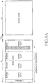
- FIG. 4 is a diagram illustrating a frame structure only for a new communication system according to an embodiment of the present invention.
- BCH is positioned in the first symbol after a preamble in the frame.
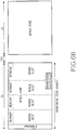
- FIGs. 5A and 5B are diagrams illustrating a frame structure only for a new communication system according to an embodiment of the present invention.
- BCH is positioned in the last symbol in the frame.
- FCH should include position information of the BCH.
- FIGs. 6A and 6B are diagrams illustrating a frame structure only for a new communication system according to an embodiment of the present invention.
- BCH is positioned in a particular symbol in the frame.
- the particular symbol can be, for example, a 24 th symbol.
- BCH is positioned over two slots.
- the BCH can occupy at least one symbol zone.
- FIG. 7 is a flowchart illustrating a process of decoding resource allocation information by a mobile station of a new system according to an embodiment of the present invention.
- a mobile station acquires synchronization using a preamble.
- the mobile station decodes frame information, i.e., FCH, and then proceeds to step 706.
- the frame information includes at least one of information indicating whether the corresponding frame is a frame only for the legacy communication system, a frame for a coexistence system, or a frame only for the new communication system, and position and size information of BCH in the frame including the BCH, using reserved bits of FCH according to the transmission scheme.
- the frame information can be provided to the mobile station using a unique preamble. That is, the mobile station can find out the frame structure corresponding to the received preamble.
- step 706 the mobile station determines whether the corresponding frame is a frame only for the legacy communication system. If it is determined that the corresponding frame is a frame only for the legacy communication system, the mobile station proceeds to step 708, and otherwise, proceeds to step 710. In step 708, the mobile station decodes a legacy MAP, and then proceeds to step 720.
- the mobile station determines in step 710 whether the corresponding frame is a frame for the coexistence system. If it is determined that the corresponding frame is a frame not for the coexistence system but only for the new communication system, the mobile station proceeds to step 712, and if the corresponding frame is a frame for the coexistence system, the mobile station proceeds to step 716.
- step 712 the mobile station, previously recognizing the position and size of BCH preset by the system, decodes the BCH.
- step 714 the mobile station decodes a new MAP only for the new communication system, and then proceeds to step 720.
- step 716 the mobile station decodes a legacy MAP and detects the presence of BCH corresponding to a GCID.
- step 718 the mobile station decodes the BCH, and then proceeds to step 720.
- step 720 the mobile station determines whether there is any resource allocated for the mobile station itself. If it is determined that there is any allocated resource, the mobile station decodes the allocated resources in step 722.
- FIG. 8 is a flowchart illustrating a process of decoding allocated resources by a mobile station according to another embodiment of the present invention.
- a mobile station acquires synchronization using a preamble.
- the mobile station acquires frame information, and then proceeds to step 806.
- the frame information can be acquired using FCH or a preamble pattern.
- the frame information includes at least one of ratio information of the downlink subframe to the uplink subframe of the frame, and position and size information of BCH.
- step 806 the mobile station determines whether the corresponding frame is a frame only for the legacy communication system. If it is determined that the corresponding frame is a frame only for the legacy communication system, the mobile station proceeds to step 808 where it decodes a legacy MAP, and then proceeds to step 818.
- the mobile station determines in step 810 whether the corresponding frame is a frame for the coexistence system. If the corresponding frame is not a frame for the coexistence system but a frame only for the new communication system, the mobile station proceeds to step 812, and if the corresponding frame is a frame for the coexistence system, the mobile station proceeds to step 814.
- step 812 the mobile station decodes BCH having predetermined position and size, and then proceeds to step 818.
- the BCH can be positioned in the first symbol after the preamble.
- step 814 the mobile station acquires DL:UL ratio information recognized by the FCH decoding.
- step 816 the mobile station decodes BCH positioned in the last symbol of the downlink subframe (DL), and then proceeds to step 818.
- step 818 the mobile station determines whether there is any resource allocated to the mobile station itself. If there are allocated resources, the mobile station decodes the corresponding resources in step 820.
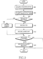
- FIG. 9 is a flowchart illustrating a process of operating according to the success/failure in BCH decoding by a mobile station according to further another embodiment of the present invention.
- a mobile station acquires synchronization using a preamble.
- the mobile station decodes BCH positioned in a preset symbol, and then proceeds to step 906.
- the BCH can be positioned in any one of the first symbol after the preamble, the last symbol of the downlink subframe zone, and a particular symbol.
- the mobile station determines whether it has succeeded in decoding of the BCH. If the mobile station has succeeded in decoding of the BCH, the mobile station decodes a new MAP for the new communication system in step 908, and then proceeds to step 914.
- step 910 the mobile station decodes FCH in step 910.
- step 912 the mobile station decodes a legacy MAP, and then proceeds to step 914.
- the mobile station can determine the presence/absence of resources allocated thereto and the position and size of the allocated resources. Therefore, the mobile station determines in step 914 whether there is any resource allocated to the mobile station itself. If there are allocated resources, the mobile station decodes the corresponding resources in step 916.
- the present invention provides a method for variably determining a ratio of the downlink subframe to the uplink subframe and transmitting common control information when the legacy communication system is replaced by the new communication system in the wireless communication system, making it possible to provide better communication services to the users.
Landscapes
- Engineering & Computer Science (AREA)
- Computer Networks & Wireless Communication (AREA)
- Signal Processing (AREA)
- Mobile Radio Communication Systems (AREA)
Claims (21)
- Verfahren zum Senden einer gemeinsamen Steuerinformation durch eine Basisstation in einem Drahtlos-Kommunikationssystem, wobei das Verfahren umfasst:Ermitteln, ob das Drahtlos-Kommunikationssystem ein koexistierendes System ist, in welchem ein Altsystem und ein neues System, das sich von dem Altsystem unterscheidet, gemeinsam vorhanden sind;wenn das Drahtlos-Kommunikationssystem ein koexistierendes System ist, Angeben einer Information für die Koexistenz des Altsystems und des neuen Systems, einer Positions- und Größeninformation einer Ressourcenzuweisungszone (207), in der eine gemeinsame Steuerinformation für das neue System gesendet werden kann, und einer Information, die zum Decodieren der Ressourcenzuweisungszone erforderlich ist, mittels eines ersten Informationselements (205) eines Abwärtsverbindungs-Teilblocks (110), in welchem Ressourcen für das Altsystem besetzt sind; undSenden der gemeinsamen Steuerinformation des neuen Systems in der Ressourcenzuweisungszone.
- Verfahren nach Anspruch 1, wobei die Ressourcenzuweisungszone (207), in der die gemeinsame Steuerinformation gesendet wird, eine Größe und eine Position hat, die auf der Grundlage eines letzten Symbols des Abwärtsverbindungs-Teilblocks (110) vordefiniert sind.
- Verfahren nach Anspruch 2, das ferner umfasst:Senden von Ressourcenverhältnisinformation einer Aufwärtsverbindung zu einer Abwärtsverbindung an einer Position, die einem letzten Symbol der Abwärtsverbindungs-Ressourcen entspricht.
- Verfahren nach Anspruch 1, wobei die Ressourcenzuweisungszone (207), in der die gemeinsame Steuerinformation gesendet wird, eine Zone ist, die einem letzten Symbol basierend auf einem Symbolverhältnis eines Abwärtsverbindungs-Teilblocks (110) mit einer minimalen Anzahl an Abwärtsverbindungs-Teilblock-Symbolen zu einem Aufwärtsverbindungs-Teilblock (120) aus Symbolverhältnissen des Abwärtsverbindungs-Teilblocks zu dem Aufwärtsverbindungs-Teilblock entspricht" das in variabler Weise entsprechend einer in dem Drahtlos-Kommunikationssystem verwendeten Bandbreite bestimmbar ist.
- Verfahren nach Anspruch 4, wobei die Ressourcenzuweisungszone (207), in der die gemeinsame Steuerinformation gesendet wird, eine Größe und eine Position hat, die auf der Grundlage eines N-ten Symbols vordefiniert ist, wenn die Anzahl an Symbolen des Abwärtsverbindungs-Teilblocks (110) von einem Minimum von N zu einem Maximum von M entsprechend einer Bandbreite variiert.
- Verfahren nach Anspruch 1, das ferner umfasst:Setzen eines Bitwertes, der die Anwesenheit des koexistierenden Systems angibt, unter Anwendung von Bits, die in dem Altsystem von allen Bits eines Blocksteuerkopfes, FCH, (201) ungenutzt sind, für das Altsystem, wenn das Drahtlos-Kommunikationssystem das koexistierende System ist.
- Verfahren nach Anspruch 6, wobei der Bitwert eine Position eines Symbols angibt, in dem die gemeinsame Steuerinformation gesendet wird.
- Verfahren nach Anspruch 1, das ferner umfasst:Festlegen der Ressourcenzuweisungszone (207) an einer vordefinierten Position, in der die gemeinsame Steuerinformation gesendet werden kann, wenn das Drahtlos-Kommunikationssystem nicht das koexistierende System ist und ein Drahtlos-Kommunikationssystem ist, in welchem nur das neue System, das aus dem Altsystem hervorgeht, existiert.
- Verfahren nach Anspruch 8, das ferner umfasst:Festlegen der vordefinierten Position als ein erstes Symbol nach einer Präambel, ein letztes Symbol des Abwärtsverbindungs-Teilblocks (110) und/oder ein spezielles Symbol in dem Abwärtsverbindungs-Teilblock; undSenden der gemeinsamen Steuerinformation des neuen Systems durch die festgelegte Symbolposition.
- Verfahren nach Anspruch 1, das ferner umfasst:Zuweisen eines gemeinsamen Steuerkanals des neuen Systems in Abhängigkeit von einer gemeinsamen Steuerinformation des Altsystems unter Anwendung einer Gruppen-Kennung, ID, die gemeinsam allen Mobilstationen des neuen Systems zugewiesen ist.
- Verfahren nach Anspruch 10, wobei die gemeinsame Steuerinformation des Altsystems MAP ist, und eine Gruppen-Kennung, die allen Mobilstationen des neuen Systems zugewiesen ist, eine Verbindungs-Kennung, CID, ist, die zur Identifizierung einer Verbindung zu einer Mobilstation des Altsystems verwendet wird.
- Verfahren zum Empfangen einer gemeinsamen Steuerinformation durch eine Mobilstation in einem Drahtlos-Kommunikationssystem, wobei das Verfahren umfasst:Decodieren (704) von Information über eine Blockstruktur, die von einer Basisstation gesendet wird,Ermitteln (710), ob das Drahtlos-Kommunikationssystem ein koexistierendes System ist, in welchem ein Altsystem und ein neues System, das sich von dem Altsystem unterscheidet, gleichzeitig existieren;Decodieren (716) von gemeinsamer Steuerinformation für das Altsystem, wenn das Drahtlos-Kommunikationssystem ein koexistierendes System ist;Erhalten von Information über eine Position und eine Größe, an der die gemeinsame Steuerinformation für das neue System gesendet wird, und von Information, die zum Decodieren einer gemeinsamen Steuerinformation gemäß dem Decodierergebnis über die gemeinsame Steuerinformation erforderlich ist; undDecodieren (718) einer gemeinsamen Steuerinformation für das neue System unter Anwendung der erhaltenen Information.
- Verfahren nach Anspruch 12, das ferner umfasst:Erhalten (720) von Ressourcenzuweisungsinformation für eine Mobilstation des neuen Systems gemäß dem Decodierergebnis über die gemeinsame Steuerinformation (207) des neuen Systems; undDecodieren (722) einer entsprechenden Ressource, wenn die Ressource der Mobilstation zugewiesen ist.
- Verfahren nach Anspruch 12, das ferner umfasst:Empfangen (814) und Decodieren einer Abwärtsverbindungs-Ressourcenverhältnisinformation;Erhalten von Information über ein letztes Symbol eines Abwärtsverbindungs-Teilblocks (110) gemäß dem Decodierergebnis; undDecodieren (816) von gemeinsamer Steuerinformation des neuen Systems, die eine Größe und eine Position hat, die auf der Grundlage eines letzten Symbols des Abwärtsverbindungs-Teilblocks vordefiniert sind.
- Verfahren nach Anspruch 12, wobei die gemeinsame Steuerinformation eine Größe und eine Position hat, die auf der Grundlage eines letzten Symbols in einem Symbolverhältnis eines Abwärtsverbindungs-Teilblocks (110) mit einer minimalen Anzahl an Abwärtsverbindungs-Teilblock-Symbolen zu einem Aufwärtsverbindungs-Teilblock (120) aus Symbolverhältnissen des Abwärtsverbindungs-Teilblocks zu dem Aufwärtsverbindungs-Teilblock vordefiniert ist, das gemäß einer Bandbreite, die in dem Drahtlos-Kommunikationssystem verwendet ist, variabel bestimmbar ist.
- Verfahren nach Anspruch 12, wobei die Information über die Blockstruktur Information umfasst, die die Koexistenz des Altsystems und des neuen Systems angibt, und aus der Basisstation unter Anwendung einiger Bits aus Bits gesendet wird, die in dem Altsystem in einem Blocksteuerkopf, FCH, (201) des Altsystems ungenutzt sind.
- Verfahren nach Anspruch 12, wobei die Information über die Blockstruktur Information umfasst, die eine Koexistenz des Altsystems und des neuen Systems angibt und die aus der Basisstation unter Anwendung einer Präambel gesendet wird, die der Information über die Blockstruktur entspricht.
- Verfahren nach Anspruch 12, das ferner umfasst:Decodieren (904) einer gemeinsamen Steuerinformation, die an einer vordefinierten Position unter Anwendung von Ressourcen mit vorbestimmter Größe gesendet wird, wenn das Drahtlos-Kommunikationssystem nicht das koexistierende System sondern ein Drahtlos-Kommunikationssystem ist, in welchem nur das aus dem Altsystem hervorgegangene neue System existiert;Decodieren (908) von MAP für das neue System gemäß dem Decodierergebnis (906) über die gemeinsame Steuerinformation; undDecodieren (916) einer Datensequenz, die der Mobilstation zugewiesen ist, entsprechend dem Decodierergebnis über MAP für das neue System.
- Verfahren nach Anspruch 18, wobei die vordefinierte Position einem ersten Symbol nach einer Präambel, einem letzten Symbol eines Abwärtsverbindungs-Teilblocks (110) und/oder einem speziellen Symbol in dem Abwärtsverbindungs-Teilblock entspricht.
- Verfahren nach Anspruch 12, das ferner umfasst:Erhalten von Symbolverhältnisinformation eines Abwärtsverbindungs-Teilblocks (110) zu einem Aufwärtsverbindungs-Teilblock (120) durch Decodieren von reservierten Bits, die in dem Altsystem in einem Blocksteuerkopf, FCH, (201) des Altsystems nicht genutzt sind.
- Verfahren nach Anspruch 12, das ferner umfasst:Erhalten von Ressourcenzuweisungsinformation entsprechend zu einer Gruppenverbindungs-Kennung, CID, die einer Mobilstation des neuen Systems zugewiesen ist, während eine gemeinsame Steuerinformation für das Altsystem decodiert wird (716);Decodieren einer gemeinsamen Steuerkanalinformation des neuen Systems, die an einer Position gesendet wird, die in der erhaltenen Ressourcenzuweisungsinformation gekennzeichnet ist; undErhalten von Ressourcenzuweisungsinformation, die einer CID zugewiesen ist, die eindeutig jeder Mobilstation zugewiesen ist, über eine MAP-Nachricht des neuen Systems, und Decodieren der entsprechenden Ressource.
Priority Applications (1)
| Application Number | Priority Date | Filing Date | Title |
|---|---|---|---|
| EP14000689.1A EP2744288B1 (de) | 2007-05-17 | 2008-05-16 | Verfahren zum Senden und Empfangen gemeinsamer Steuerinformationen in einem drahtlosen Kommunikationssystem |
Applications Claiming Priority (1)
| Application Number | Priority Date | Filing Date | Title |
|---|---|---|---|
| KR1020070048301A KR101454482B1 (ko) | 2007-05-17 | 2007-05-17 | 무선 통신 시스템에서 공통 제어 정보 송수신 시스템 및방법 |
Related Child Applications (2)
| Application Number | Title | Priority Date | Filing Date |
|---|---|---|---|
| EP14000689.1A Division EP2744288B1 (de) | 2007-05-17 | 2008-05-16 | Verfahren zum Senden und Empfangen gemeinsamer Steuerinformationen in einem drahtlosen Kommunikationssystem |
| EP14000689.1A Division-Into EP2744288B1 (de) | 2007-05-17 | 2008-05-16 | Verfahren zum Senden und Empfangen gemeinsamer Steuerinformationen in einem drahtlosen Kommunikationssystem |
Publications (3)
| Publication Number | Publication Date |
|---|---|
| EP1993307A2 EP1993307A2 (de) | 2008-11-19 |
| EP1993307A3 EP1993307A3 (de) | 2013-01-23 |
| EP1993307B1 true EP1993307B1 (de) | 2018-04-11 |
Family
ID=39736925
Family Applications (2)
| Application Number | Title | Priority Date | Filing Date |
|---|---|---|---|
| EP08009132.5A Not-in-force EP1993307B1 (de) | 2007-05-17 | 2008-05-16 | System und verfahren zum senden und empfangen gemeinsamer steuerinformationen in einem drahtlosen kommunikationssystem |
| EP14000689.1A Ceased EP2744288B1 (de) | 2007-05-17 | 2008-05-16 | Verfahren zum Senden und Empfangen gemeinsamer Steuerinformationen in einem drahtlosen Kommunikationssystem |
Family Applications After (1)
| Application Number | Title | Priority Date | Filing Date |
|---|---|---|---|
| EP14000689.1A Ceased EP2744288B1 (de) | 2007-05-17 | 2008-05-16 | Verfahren zum Senden und Empfangen gemeinsamer Steuerinformationen in einem drahtlosen Kommunikationssystem |
Country Status (5)
| Country | Link |
|---|---|
| US (1) | US8155062B2 (de) |
| EP (2) | EP1993307B1 (de) |
| JP (1) | JP4898741B2 (de) |
| KR (1) | KR101454482B1 (de) |
| CN (2) | CN103037523B (de) |
Families Citing this family (45)
| Publication number | Priority date | Publication date | Assignee | Title |
|---|---|---|---|---|
| KR101387486B1 (ko) * | 2007-03-14 | 2014-04-21 | 엘지전자 주식회사 | 이종 모드 지원 무선 데이터 통신 방법 |
| US8279812B2 (en) * | 2007-07-12 | 2012-10-02 | Industrial Technology Research Institute | Method and module for constructing a frame structure in communication systems |
| US8265096B2 (en) * | 2007-07-12 | 2012-09-11 | Industrial Technology Research Institute | Method for constructing frame structures |
| KR101422012B1 (ko) * | 2007-10-19 | 2014-07-23 | 엘지전자 주식회사 | 제어채널 생성 방법, 제어채널 복호화 방법, 이를 구현하는기지국 및 단말 |
| US8126408B2 (en) * | 2008-01-22 | 2012-02-28 | Provigent Ltd | Multi-mode wireless communication link |
| KR20090094736A (ko) * | 2008-03-03 | 2009-09-08 | 엘지전자 주식회사 | 레거시 시스템을 지원하기 위한 정보전송방법 |
| JP5215101B2 (ja) * | 2008-07-08 | 2013-06-19 | 株式会社エヌ・ティ・ティ・ドコモ | 無線基地局装置及び移動端末装置 |
| US9225481B2 (en) * | 2008-08-11 | 2015-12-29 | Qualcomm Incorporated | Downlink grants in a multicarrier wireless communication system |
| US8670376B2 (en) | 2008-08-12 | 2014-03-11 | Qualcomm Incorporated | Multi-carrier grant design |
| US20100124184A1 (en) * | 2008-11-14 | 2010-05-20 | Qualcomm Incorporated | Methods and systems with frame structure for improved adjacent channel co-existence |
| EP2194751B1 (de) * | 2008-12-02 | 2013-01-23 | Samsung Electronics Co., Ltd. | Übertragung von Planungszuweisungen in mehrfachen Operationsbandbreiten |
| US8243648B2 (en) * | 2008-12-19 | 2012-08-14 | Intel Corporation | Spatial reuse techniques with wireless network relays |
| EP2374296B8 (de) * | 2008-12-23 | 2012-11-21 | Telecom Italia S.p.A. | Verfahren zur dimensionierung von funkzugangsnetzen, entsprechendes system und computerprogrammprodukt |
| US8531805B2 (en) * | 2009-03-13 | 2013-09-10 | Qualcomm Incorporated | Gated diode having at least one lightly-doped drain (LDD) implant blocked and circuits and methods employing same |
| US8665570B2 (en) | 2009-03-13 | 2014-03-04 | Qualcomm Incorporated | Diode having a pocket implant blocked and circuits and methods employing same |
| WO2010114233A2 (en) * | 2009-03-31 | 2010-10-07 | Lg Electronics Inc. | Method for allocating resource to uplink control signal in wireless communication system and apparatus therefor |
| WO2010129295A1 (en) * | 2009-04-28 | 2010-11-11 | Zte U.S.A., Inc. | Method and system for dynamic adjustment of downlink/uplink allocation ratio in lte/tdd systems |
| US9106378B2 (en) | 2009-06-10 | 2015-08-11 | Qualcomm Incorporated | Systems, apparatus and methods for communicating downlink information |
| US9144037B2 (en) | 2009-08-11 | 2015-09-22 | Qualcomm Incorporated | Interference mitigation by puncturing transmission of interfering cells |
| US9277566B2 (en) | 2009-09-14 | 2016-03-01 | Qualcomm Incorporated | Cross-subframe control channel design |
| US8942192B2 (en) | 2009-09-15 | 2015-01-27 | Qualcomm Incorporated | Methods and apparatus for subframe interlacing in heterogeneous networks |
| JP5370891B2 (ja) * | 2010-02-23 | 2013-12-18 | 独立行政法人情報通信研究機構 | 無線通信システム,該システムに設置される共存マネージャー,及び無線通信方法 |
| US9392608B2 (en) | 2010-04-13 | 2016-07-12 | Qualcomm Incorporated | Resource partitioning information for enhanced interference coordination |
| US9271167B2 (en) | 2010-04-13 | 2016-02-23 | Qualcomm Incorporated | Determination of radio link failure with enhanced interference coordination and cancellation |
| US9125072B2 (en) | 2010-04-13 | 2015-09-01 | Qualcomm Incorporated | Heterogeneous network (HetNet) user equipment (UE) radio resource management (RRM) measurements |
| US9226288B2 (en) | 2010-04-13 | 2015-12-29 | Qualcomm Incorporated | Method and apparatus for supporting communications in a heterogeneous network |
| WO2011145460A1 (ja) | 2010-05-21 | 2011-11-24 | シャープ株式会社 | 移動通信システム、基地局装置、移動局装置および通信方法 |
| US9402259B2 (en) | 2010-07-12 | 2016-07-26 | Lg Electronics Inc. | Device and method for transmitting and receiving control information in a wireless communication system simultaneously supporting a plurality of wireless communication methods |
| CN106028355A (zh) * | 2010-09-28 | 2016-10-12 | 富士通株式会社 | 第一通信系统 |
| US8886190B2 (en) | 2010-10-08 | 2014-11-11 | Qualcomm Incorporated | Method and apparatus for measuring cells in the presence of interference |
| KR101883467B1 (ko) * | 2010-12-23 | 2018-07-31 | 한국전자통신연구원 | 통신 시스템에서 데이터 송수신 장치 및 방법 |
| JP5655867B2 (ja) | 2011-01-27 | 2015-01-21 | 日本電気株式会社 | 基地局、移動局、通信制御システム、及び通信制御方法 |
| EP2712223A4 (de) * | 2011-05-19 | 2015-11-18 | Nec Corp | Spektrumssteuerungssystem, spektrumssteuerungsverfahren, drahtloses kommunikationssystem und computerlesbare medien |
| CN104067667A (zh) | 2012-01-23 | 2014-09-24 | 英特尔公司 | 用于集成的多rat异类网络的网络辅助的用户关联和卸载技术 |
| JP5941305B2 (ja) * | 2012-03-14 | 2016-06-29 | シャープ株式会社 | 移動局装置、基地局装置、無線通信システム、無線通信方法および集積回路 |
| DE112013002096B4 (de) * | 2012-04-18 | 2016-09-01 | Mitsubishi Electric Corporation | Funkkommunikationssystem, Funkkommunikationsvorrichtung, und Funkkommunikationsverfahren |
| GB2504544A (en) * | 2012-08-02 | 2014-02-05 | Nec Corp | Resource allocation signalling within an enhanced Physical Downlink Control Channel (ePDCCH) |
| US9942008B1 (en) * | 2014-02-10 | 2018-04-10 | Marvell International Ltd. | Systems and methods for range extension by time repetition |
| US9762354B2 (en) | 2015-01-27 | 2017-09-12 | Sony Corporation | Signaling methods and apparatus |
| CN105992343B (zh) * | 2015-01-30 | 2020-05-26 | 电信科学技术研究院 | 一种信号发送方法、接收方法及装置 |
| SG11201800981SA (en) * | 2015-09-11 | 2018-03-28 | Sony Corp | Communication control device, communication control determination device, and method |
| US10225828B2 (en) * | 2015-11-02 | 2019-03-05 | Intel IP Corporation | Apparatus, system and method of communicating control information in a physical layer protocol data unit (PPDU) |
| US11324006B2 (en) * | 2018-05-11 | 2022-05-03 | Qualcomm Incorporated | Signaling for sub-slot time-domain resource allocation |
| CN112312347B (zh) * | 2019-07-25 | 2022-05-31 | 华为技术有限公司 | 一种通信方法、装置及存储介质 |
| US20230120992A1 (en) * | 2021-03-26 | 2023-04-20 | Semiconductor Components Industries, Llc | Wi-fi based fixed wireless access protocol |
Family Cites Families (27)
| Publication number | Priority date | Publication date | Assignee | Title |
|---|---|---|---|---|
| JP3849551B2 (ja) * | 2002-03-05 | 2006-11-22 | ソニー株式会社 | 無線通信システム、無線通信装置及び方法、並びにコンピュータ・プログラム |
| US6920121B2 (en) * | 2003-03-17 | 2005-07-19 | Qprs Limited | Quality packet radio service for a general packet radio system |
| KR100684305B1 (ko) * | 2003-07-18 | 2007-02-16 | 한국전자통신연구원 | 무선 휴대 인터넷 시스템에서의 무선자원 할당 방법 및 장치 |
| US8233462B2 (en) | 2003-10-15 | 2012-07-31 | Qualcomm Incorporated | High speed media access control and direct link protocol |
| EP1730864B1 (de) * | 2004-04-02 | 2018-10-31 | Apple Inc. | Drahtlose kommunikationsverfahren, systeme und signalstrukturen |
| US7580388B2 (en) | 2004-06-01 | 2009-08-25 | Lg Electronics Inc. | Method and apparatus for providing enhanced messages on common control channel in wireless communication system |
| EP3537681B1 (de) * | 2004-06-24 | 2020-10-07 | Apple Inc. | Präambeln in einem ofdma-system |
| KR100830163B1 (ko) | 2005-04-20 | 2008-05-20 | 삼성전자주식회사 | 주파수 오버레이 통신 시스템에서 신호 송수신 장치 및 방법 |
| KR100703287B1 (ko) * | 2005-07-20 | 2007-04-03 | 삼성전자주식회사 | 통신 시스템에서 자원 할당 정보 송수신 시스템 및 방법 |
| DE102005042536A1 (de) * | 2005-09-07 | 2007-03-15 | Siemens Ag | Verfahren zum Betreiben einer Funk-Kommunikation in einem Multi-Funkverbindungs-Kommunikationsssystem |
| KR100782844B1 (ko) * | 2006-01-12 | 2007-12-06 | 삼성전자주식회사 | 무선랜에서 채널 본딩을 이용하여 데이터 프레임을전송하는 방법 및 장치 |
| ES2380787T3 (es) * | 2006-05-16 | 2012-05-18 | Nokia Siemens Networks Gmbh & Co. Kg | Método para transmitir de manera segura mapas de bits ACK/NACK cortos en un proceso ARQ dentro de sistemas compatibles con EDGE |
| US8462676B2 (en) * | 2006-10-17 | 2013-06-11 | Intel Corporation | Frame structure for support of large delay spread deployment scenarios |
| WO2008049028A1 (en) * | 2006-10-17 | 2008-04-24 | Intel Corporation | Device, system, and method for partitioning and framing communication signals in broadband wireless access networks |
| US8204036B2 (en) * | 2007-02-28 | 2012-06-19 | Motorola Mobility, Inc. | Method and apparatus for coexistence |
| US20080219203A1 (en) * | 2007-03-09 | 2008-09-11 | Industrial Technology Research Institute. | Method for mac process and flexible connection in wireless multi-hop relaying network |
| KR101387486B1 (ko) * | 2007-03-14 | 2014-04-21 | 엘지전자 주식회사 | 이종 모드 지원 무선 데이터 통신 방법 |
| KR100965128B1 (ko) * | 2007-03-21 | 2010-06-23 | 삼성전자주식회사 | 광대역 무선통신 시스템에서 초기 접속 수행 장치 및 방법 |
| US8228850B2 (en) * | 2007-10-30 | 2012-07-24 | Futurewei Technologies, Inc. | Method and apparatus for transmitting control information in a system with new and legacy mobile stations |
| US8477697B2 (en) * | 2007-12-06 | 2013-07-02 | Telefonaktiebolaget Lm Ericsson (Publ) | Interlacing wireless communication frames |
| KR20090094736A (ko) * | 2008-03-03 | 2009-09-08 | 엘지전자 주식회사 | 레거시 시스템을 지원하기 위한 정보전송방법 |
| KR101542515B1 (ko) * | 2008-04-07 | 2015-08-12 | 삼성전자주식회사 | 다중 홉 중계 방식을 사용하는 광대역 무선통신 시스템에서 서로 다른 시스템 지원 장치 및 방법 |
| US8432870B2 (en) * | 2008-07-11 | 2013-04-30 | Nokia Siemens Networks Oy | Handover techniques between legacy and updated wireless networks |
| GB0814483D0 (en) * | 2008-08-07 | 2008-09-10 | Cambridge Silicon Radio Ltd | Uwb coexistence scheme |
| KR101667826B1 (ko) * | 2008-11-04 | 2016-10-19 | 애플 인크. | 제 1 캐리어에서 제 2, 다른 캐리어에서의 제어 정보를 표시하기 위해 다운링크 제어 구조를 제공하는 방법 |
| KR101692723B1 (ko) * | 2009-06-17 | 2017-01-04 | 엘지전자 주식회사 | H-fdd 동작을 지원하는 프레임 구조를 이용하여 통신을 수행하는 방법 |
| KR101578010B1 (ko) * | 2009-07-03 | 2015-12-16 | 엘지전자 주식회사 | 레거시 지원 모드에서 단말의 레인징 |
-
2007
- 2007-05-17 KR KR1020070048301A patent/KR101454482B1/ko not_active Expired - Fee Related
-
2008
- 2008-05-15 JP JP2008128004A patent/JP4898741B2/ja not_active Expired - Fee Related
- 2008-05-15 US US12/120,745 patent/US8155062B2/en active Active
- 2008-05-16 EP EP08009132.5A patent/EP1993307B1/de not_active Not-in-force
- 2008-05-16 EP EP14000689.1A patent/EP2744288B1/de not_active Ceased
- 2008-05-19 CN CN201210584026.6A patent/CN103037523B/zh not_active Expired - Fee Related
- 2008-05-19 CN CN2008102154189A patent/CN101350700B/zh not_active Expired - Fee Related
Non-Patent Citations (1)
| Title |
|---|
| None * |
Also Published As
| Publication number | Publication date |
|---|---|
| EP1993307A2 (de) | 2008-11-19 |
| JP2008289152A (ja) | 2008-11-27 |
| CN101350700B (zh) | 2013-02-13 |
| CN103037523A (zh) | 2013-04-10 |
| JP4898741B2 (ja) | 2012-03-21 |
| US8155062B2 (en) | 2012-04-10 |
| EP1993307A3 (de) | 2013-01-23 |
| EP2744288A2 (de) | 2014-06-18 |
| KR20080102026A (ko) | 2008-11-24 |
| EP2744288A3 (de) | 2014-10-08 |
| CN103037523B (zh) | 2015-08-19 |
| KR101454482B1 (ko) | 2014-10-27 |
| US20080285513A1 (en) | 2008-11-20 |
| EP2744288B1 (de) | 2017-08-09 |
| CN101350700A (zh) | 2009-01-21 |
Similar Documents
| Publication | Publication Date | Title |
|---|---|---|
| EP1993307B1 (de) | System und verfahren zum senden und empfangen gemeinsamer steuerinformationen in einem drahtlosen kommunikationssystem | |
| EP1718096B1 (de) | Anzeige des Frame Offsets von Multicast Broadcast Service Datenbursts in einer MBS-MAP Nachricht | |
| US7664087B2 (en) | Method for generating a frame in an orthogonal frequency division multiple access communication system | |
| JP5477490B2 (ja) | 無線通信システムの制御チャネルにおける、無線リソース割当方法のための装置 | |
| JP2010517461A (ja) | 異種通信システム間のサービスインターワーキングのための方法及びシステム | |
| JP2014039272A (ja) | Ofdma通信システムにおけるスティッキー領域割振りのための方法およびシステム | |
| US20130242925A1 (en) | System and method for transmitting and receiving frequency resource information in a frequency overlay | |
| JP4906976B1 (ja) | 基地局、移動局及び移動通信方法 | |
| JP5062256B2 (ja) | 無線通信システムにおける制御情報送信及び受信方法と,これを用いる無線基地局及び無線端末 | |
| KR20090040018A (ko) | 제어채널 생성 방법, 제어채널 복호화 방법, 이를 구현하는기지국 및 단말 | |
| CN101931877A (zh) | 单播业务控制信道的配置指示方法、信息发送及接收方法 | |
| CN102209393B (zh) | 一种调用下行帧中资源的方法 | |
| US20090185633A1 (en) | Method and System for Specifying the Location of Data Bursts |
Legal Events
| Date | Code | Title | Description |
|---|---|---|---|
| PUAI | Public reference made under article 153(3) epc to a published international application that has entered the european phase |
Free format text: ORIGINAL CODE: 0009012 |
|
| 17P | Request for examination filed |
Effective date: 20080516 |
|
| AK | Designated contracting states |
Kind code of ref document: A2 Designated state(s): AT BE BG CH CY CZ DE DK EE ES FI FR GB GR HR HU IE IS IT LI LT LU LV MC MT NL NO PL PT RO SE SI SK TR |
|
| AX | Request for extension of the european patent |
Extension state: AL BA MK RS |
|
| RAP1 | Party data changed (applicant data changed or rights of an application transferred) |
Owner name: SAMSUNG ELECTRONICS CO., LTD. |
|
| PUAL | Search report despatched |
Free format text: ORIGINAL CODE: 0009013 |
|
| RIC1 | Information provided on ipc code assigned before grant |
Ipc: H04W 72/04 20090101AFI20121211BHEP |
|
| AK | Designated contracting states |
Kind code of ref document: A3 Designated state(s): AT BE BG CH CY CZ DE DK EE ES FI FR GB GR HR HU IE IS IT LI LT LU LV MC MT NL NO PL PT RO SE SI SK TR |
|
| AX | Request for extension of the european patent |
Extension state: AL BA MK RS |
|
| RIC1 | Information provided on ipc code assigned before grant |
Ipc: H04W 72/04 20090101AFI20121218BHEP |
|
| AKX | Designation fees paid |
Designated state(s): DE ES FR GB NL |
|
| 17Q | First examination report despatched |
Effective date: 20161007 |
|
| REG | Reference to a national code |
Ref country code: DE Ref legal event code: R079 Ref document number: 602008054746 Country of ref document: DE Free format text: PREVIOUS MAIN CLASS: H04Q0007360000 Ipc: H04W0016140000 |
|
| GRAP | Despatch of communication of intention to grant a patent |
Free format text: ORIGINAL CODE: EPIDOSNIGR1 |
|
| RIC1 | Information provided on ipc code assigned before grant |
Ipc: H04W 16/14 20090101AFI20171020BHEP Ipc: H04W 48/12 20090101ALN20171020BHEP Ipc: H04W 72/04 20090101ALI20171020BHEP |
|
| INTG | Intention to grant announced |
Effective date: 20171114 |
|
| GRAS | Grant fee paid |
Free format text: ORIGINAL CODE: EPIDOSNIGR3 |
|
| GRAA | (expected) grant |
Free format text: ORIGINAL CODE: 0009210 |
|
| AK | Designated contracting states |
Kind code of ref document: B1 Designated state(s): DE ES FR GB NL |
|
| REG | Reference to a national code |
Ref country code: GB Ref legal event code: FG4D |
|
| REG | Reference to a national code |
Ref country code: DE Ref legal event code: R096 Ref document number: 602008054746 Country of ref document: DE |
|
| REG | Reference to a national code |
Ref country code: NL Ref legal event code: MP Effective date: 20180411 |
|
| PG25 | Lapsed in a contracting state [announced via postgrant information from national office to epo] |
Ref country code: NL Free format text: LAPSE BECAUSE OF FAILURE TO SUBMIT A TRANSLATION OF THE DESCRIPTION OR TO PAY THE FEE WITHIN THE PRESCRIBED TIME-LIMIT Effective date: 20180411 |
|
| PG25 | Lapsed in a contracting state [announced via postgrant information from national office to epo] |
Ref country code: ES Free format text: LAPSE BECAUSE OF FAILURE TO SUBMIT A TRANSLATION OF THE DESCRIPTION OR TO PAY THE FEE WITHIN THE PRESCRIBED TIME-LIMIT Effective date: 20180411 |
|
| REG | Reference to a national code |
Ref country code: DE Ref legal event code: R097 Ref document number: 602008054746 Country of ref document: DE |
|
| PLBE | No opposition filed within time limit |
Free format text: ORIGINAL CODE: 0009261 |
|
| STAA | Information on the status of an ep patent application or granted ep patent |
Free format text: STATUS: NO OPPOSITION FILED WITHIN TIME LIMIT |
|
| 26N | No opposition filed |
Effective date: 20190114 |
|
| PG25 | Lapsed in a contracting state [announced via postgrant information from national office to epo] |
Ref country code: FR Free format text: LAPSE BECAUSE OF NON-PAYMENT OF DUE FEES Effective date: 20180611 |
|
| PGFP | Annual fee paid to national office [announced via postgrant information from national office to epo] |
Ref country code: DE Payment date: 20230420 Year of fee payment: 16 |
|
| PGFP | Annual fee paid to national office [announced via postgrant information from national office to epo] |
Ref country code: GB Payment date: 20230420 Year of fee payment: 16 |
|
| REG | Reference to a national code |
Ref country code: DE Ref legal event code: R119 Ref document number: 602008054746 Country of ref document: DE |
|
| GBPC | Gb: european patent ceased through non-payment of renewal fee |
Effective date: 20240516 |
|
| PG25 | Lapsed in a contracting state [announced via postgrant information from national office to epo] |
Ref country code: DE Free format text: LAPSE BECAUSE OF NON-PAYMENT OF DUE FEES Effective date: 20241203 |
|
| PG25 | Lapsed in a contracting state [announced via postgrant information from national office to epo] |
Ref country code: GB Free format text: LAPSE BECAUSE OF NON-PAYMENT OF DUE FEES Effective date: 20240516 |