EP1993496B1 - Châssis insonorisé à régulation d'ambiance - Google Patents
Châssis insonorisé à régulation d'ambiance Download PDFInfo
- Publication number
- EP1993496B1 EP1993496B1 EP07713291.8A EP07713291A EP1993496B1 EP 1993496 B1 EP1993496 B1 EP 1993496B1 EP 07713291 A EP07713291 A EP 07713291A EP 1993496 B1 EP1993496 B1 EP 1993496B1
- Authority
- EP
- European Patent Office
- Prior art keywords
- rack
- noise
- air
- duct
- microphone
- Prior art date
- Legal status (The legal status is an assumption and is not a legal conclusion. Google has not performed a legal analysis and makes no representation as to the accuracy of the status listed.)
- Active
Links
Images



Classifications
-
- H—ELECTRICITY
- H05—ELECTRIC TECHNIQUES NOT OTHERWISE PROVIDED FOR
- H05K—PRINTED CIRCUITS; CASINGS OR CONSTRUCTIONAL DETAILS OF ELECTRIC APPARATUS; MANUFACTURE OF ASSEMBLAGES OF ELECTRICAL COMPONENTS
- H05K7/00—Constructional details common to different types of electric apparatus
- H05K7/20—Modifications to facilitate cooling, ventilating, or heating
- H05K7/20709—Modifications to facilitate cooling, ventilating, or heating for server racks or cabinets; for data centers, e.g. 19-inch computer racks
- H05K7/20718—Forced ventilation of a gaseous coolant
- H05K7/20736—Forced ventilation of a gaseous coolant within cabinets for removing heat from server blades
-
- G—PHYSICS
- G10—MUSICAL INSTRUMENTS; ACOUSTICS
- G10K—SOUND-PRODUCING DEVICES; METHODS OR DEVICES FOR PROTECTING AGAINST, OR FOR DAMPING, NOISE OR OTHER ACOUSTIC WAVES IN GENERAL; ACOUSTICS NOT OTHERWISE PROVIDED FOR
- G10K11/00—Methods or devices for transmitting, conducting or directing sound in general; Methods or devices for protecting against, or for damping, noise or other acoustic waves in general
- G10K11/16—Methods or devices for protecting against, or for damping, noise or other acoustic waves in general
- G10K11/175—Methods or devices for protecting against, or for damping, noise or other acoustic waves in general using interference effects; Masking sound
- G10K11/178—Methods or devices for protecting against, or for damping, noise or other acoustic waves in general using interference effects; Masking sound by electro-acoustically regenerating the original acoustic waves in anti-phase
- G10K11/1781—Methods or devices for protecting against, or for damping, noise or other acoustic waves in general using interference effects; Masking sound by electro-acoustically regenerating the original acoustic waves in anti-phase characterised by the analysis of input or output signals, e.g. frequency range, modes, transfer functions
- G10K11/17821—Methods or devices for protecting against, or for damping, noise or other acoustic waves in general using interference effects; Masking sound by electro-acoustically regenerating the original acoustic waves in anti-phase characterised by the analysis of input or output signals, e.g. frequency range, modes, transfer functions characterised by the analysis of the input signals only
- G10K11/17823—Reference signals, e.g. ambient acoustic environment
-
- G—PHYSICS
- G10—MUSICAL INSTRUMENTS; ACOUSTICS
- G10K—SOUND-PRODUCING DEVICES; METHODS OR DEVICES FOR PROTECTING AGAINST, OR FOR DAMPING, NOISE OR OTHER ACOUSTIC WAVES IN GENERAL; ACOUSTICS NOT OTHERWISE PROVIDED FOR
- G10K11/00—Methods or devices for transmitting, conducting or directing sound in general; Methods or devices for protecting against, or for damping, noise or other acoustic waves in general
- G10K11/16—Methods or devices for protecting against, or for damping, noise or other acoustic waves in general
- G10K11/175—Methods or devices for protecting against, or for damping, noise or other acoustic waves in general using interference effects; Masking sound
- G10K11/178—Methods or devices for protecting against, or for damping, noise or other acoustic waves in general using interference effects; Masking sound by electro-acoustically regenerating the original acoustic waves in anti-phase
- G10K11/1783—Methods or devices for protecting against, or for damping, noise or other acoustic waves in general using interference effects; Masking sound by electro-acoustically regenerating the original acoustic waves in anti-phase handling or detecting of non-standard events or conditions, e.g. changing operating modes under specific operating conditions
-
- G—PHYSICS
- G10—MUSICAL INSTRUMENTS; ACOUSTICS
- G10K—SOUND-PRODUCING DEVICES; METHODS OR DEVICES FOR PROTECTING AGAINST, OR FOR DAMPING, NOISE OR OTHER ACOUSTIC WAVES IN GENERAL; ACOUSTICS NOT OTHERWISE PROVIDED FOR
- G10K11/00—Methods or devices for transmitting, conducting or directing sound in general; Methods or devices for protecting against, or for damping, noise or other acoustic waves in general
- G10K11/16—Methods or devices for protecting against, or for damping, noise or other acoustic waves in general
- G10K11/175—Methods or devices for protecting against, or for damping, noise or other acoustic waves in general using interference effects; Masking sound
- G10K11/178—Methods or devices for protecting against, or for damping, noise or other acoustic waves in general using interference effects; Masking sound by electro-acoustically regenerating the original acoustic waves in anti-phase
- G10K11/1785—Methods, e.g. algorithms; Devices
- G10K11/17853—Methods, e.g. algorithms; Devices of the filter
- G10K11/17854—Methods, e.g. algorithms; Devices of the filter the filter being an adaptive filter
-
- G—PHYSICS
- G10—MUSICAL INSTRUMENTS; ACOUSTICS
- G10K—SOUND-PRODUCING DEVICES; METHODS OR DEVICES FOR PROTECTING AGAINST, OR FOR DAMPING, NOISE OR OTHER ACOUSTIC WAVES IN GENERAL; ACOUSTICS NOT OTHERWISE PROVIDED FOR
- G10K11/00—Methods or devices for transmitting, conducting or directing sound in general; Methods or devices for protecting against, or for damping, noise or other acoustic waves in general
- G10K11/16—Methods or devices for protecting against, or for damping, noise or other acoustic waves in general
- G10K11/175—Methods or devices for protecting against, or for damping, noise or other acoustic waves in general using interference effects; Masking sound
- G10K11/178—Methods or devices for protecting against, or for damping, noise or other acoustic waves in general using interference effects; Masking sound by electro-acoustically regenerating the original acoustic waves in anti-phase
- G10K11/1785—Methods, e.g. algorithms; Devices
- G10K11/17861—Methods, e.g. algorithms; Devices using additional means for damping sound, e.g. using sound absorbing panels
-
- G—PHYSICS
- G10—MUSICAL INSTRUMENTS; ACOUSTICS
- G10K—SOUND-PRODUCING DEVICES; METHODS OR DEVICES FOR PROTECTING AGAINST, OR FOR DAMPING, NOISE OR OTHER ACOUSTIC WAVES IN GENERAL; ACOUSTICS NOT OTHERWISE PROVIDED FOR
- G10K11/00—Methods or devices for transmitting, conducting or directing sound in general; Methods or devices for protecting against, or for damping, noise or other acoustic waves in general
- G10K11/16—Methods or devices for protecting against, or for damping, noise or other acoustic waves in general
- G10K11/175—Methods or devices for protecting against, or for damping, noise or other acoustic waves in general using interference effects; Masking sound
- G10K11/178—Methods or devices for protecting against, or for damping, noise or other acoustic waves in general using interference effects; Masking sound by electro-acoustically regenerating the original acoustic waves in anti-phase
- G10K11/1787—General system configurations
- G10K11/17879—General system configurations using both a reference signal and an error signal
- G10K11/17881—General system configurations using both a reference signal and an error signal the reference signal being an acoustic signal, e.g. recorded with a microphone
-
- H—ELECTRICITY
- H05—ELECTRIC TECHNIQUES NOT OTHERWISE PROVIDED FOR
- H05K—PRINTED CIRCUITS; CASINGS OR CONSTRUCTIONAL DETAILS OF ELECTRIC APPARATUS; MANUFACTURE OF ASSEMBLAGES OF ELECTRICAL COMPONENTS
- H05K7/00—Constructional details common to different types of electric apparatus
- H05K7/20—Modifications to facilitate cooling, ventilating, or heating
- H05K7/20709—Modifications to facilitate cooling, ventilating, or heating for server racks or cabinets; for data centers, e.g. 19-inch computer racks
- H05K7/20718—Forced ventilation of a gaseous coolant
- H05K7/20727—Forced ventilation of a gaseous coolant within server blades for removing heat from heat source
-
- G—PHYSICS
- G10—MUSICAL INSTRUMENTS; ACOUSTICS
- G10K—SOUND-PRODUCING DEVICES; METHODS OR DEVICES FOR PROTECTING AGAINST, OR FOR DAMPING, NOISE OR OTHER ACOUSTIC WAVES IN GENERAL; ACOUSTICS NOT OTHERWISE PROVIDED FOR
- G10K2210/00—Details of active noise control [ANC] covered by G10K11/178 but not provided for in any of its subgroups
- G10K2210/10—Applications
- G10K2210/11—Computers, i.e. ANC of the noise created by cooling fan, hard drive or the like
Definitions
- the disclosure relates to cabinets (racks) for mounting electronic equipment (referred to herein as “blade chassis”) and, more particularly, to reducing and controlling noise generated within a blade chassis.
- US5636286A discloses an active noise reduction device for reducing the noise produced by cooling fans in a computer.
- a first microphone is arranged in a duct near the first end opening for detecting noise
- a second microphone is arranged in the duct near the second end opening.
- a speaker is arranged in the duct near the second opening, and a controller controls the speaker in response to outputs of the first and second microphones for reducing the noise produced in the casing.
- the speaker makes a sound having a reverse phase to that of the noise produced in the computer.
- US2002154481A1 defines a chassis for housing components includes a shell having an intake duct and an exhaust duct.
- the intake duct and the exhaust duct include active and/or passive noise attenuating features for attenuating noise generated within the chassis, which allows the chassis to operate more quietly.
- US2004070932A1 shows a method for controlling a speed of at least one cooling fan in response to a temperature of the cabinet, and, controlling the speed of the at least one cooling fan in response to a position of an access panel relative to the cabinet.
- Servers and similar electronic devices may be deployed in two different manners, the traditional tower server chassis, or a rack-mountable chassis.
- tower servers were the standard, but over the past few years, rack-mounting servers has become very popular because it allows for increased manageability, consolidation, security, expansion and modularity, helping to lower the cost of deploying servers.
- rack-mounting or “rack-mounted”, or “rack-mount” servers are something that only makes sense for the largest companies, with mainframes and huge “glass house” data centers. In reality, anyone may take advantage of rack-mounting servers and gain their benefits.
- data storage "farms” such as RAID (Redundant Arrays of Independent Disks, or Drives) disk storage racks have similar or equivalent issues, as will other heat-producing electrical devices, such as massively parallel unit (such as hypercube) and the like.
- Racks are typically measured in rack units or "U's"; each U is 44.45mm ( 1.75") high.
- racks are available in two heights - a 24U short rack and a 42U full rack.
- Computer companies offer a variety of servers to be mounted inside the racks in sizes varying from 1U through 5U. Among the most popular being the rack-dense 1U and 2U servers.
- Blade server refers to a self-contained computer server, designed for high density.
- a blade server is a server chassis housing multiple thin, modular electronic circuit boards, known as server blade s or a modular blades.
- module blades refers to a thin, modular electronic circuit board containing one, two, or more microprocessors and memory, that is intended for a single, dedicated application (such as serving Web pages) and that can be easily inserted into a blade server.
- the ultimate temperatures seen by internal server components will vary from server to server depending on the configuration, application, position in the rack, position in the data center, the amount of cabling, etc.
- Modern servers are typically designed to cool from front to back and are tested to meet elevated temperatures exceeding what is commonly found even in the worst-case locations in a data center.
- Conventional servers are designed for a 35° C (95° F) inlet temperature (into the front server surface) at maximum component power dissipations. This means that when run at full load, internal components are maintained below their recommended guidelines, or below the more stringent guidelines imposed by the manufacturer.
- a redundantly cooled system the components meet these temperature requirements even in the event of a fan failure.
- servers are usually designed to cool to meet the requirements of future processor speeds, up to the maximum speed expected (based on, for example, the manufacturer's specification).
- the server must be operating at maximum power (a maximized application, maximum processor speed) in an environment exceeding 35° C (95° F). Since many data centers are cooled to the low 20° C (68° F) range, there should be significant margin.
- High-density servers often have reduced system airflow due to the added impact (for example convection and/or conduction) of the rack, cables, and cable management arm(s).
- Factors for system-reduced airflow include the following:
- FIG. 3 illustrates a 1U dense server (for rack-mounting) with a cooling blower at the middle of the unit, and is exemplary of the prior art.
- FIG. 4 illustrates a 4U chassis with front to back cooling airflow, as is exemplary of the prior art.
- FIG. 5 illustrates a rack with eight auxiliary fans mounted lengthwise (vertical, as illustrated) on the front door, as is exemplary of the prior art.
- Rack-mount servers themselves are major noise sources and may produce a noise level of more then 80 dBA, which is regarded as very loud noise.
- Conservative solutions are based on sealing the rack(s) with barrier materials such as steel, tin, rubber sheets, etc, and/or one or more lining of sound-absorbing materials on the interior side(s) of the rack panels, and quieting the outlets/inlets by installing passive mufflers which are a kind of a metal or plastic or any rigid material maze with absorbing materials glued on its internal walls. This procedure may cause thermal problems by restricting the airflow ability, and preventing efficient heat dissipation.
- the problem is usually solved by adding auxiliary quiet blowers at the top of the rack or on one of its walls, and arranging a less effective passive muffler at the air inlet.
- quiet blowers are typically accompanied by poor airflow capacity, and acoustic mufflers are designed to block noise by turning the air through different angles (directions) and hence reducing its velocity.
- the muffler operation results in additional negative impact to the airflow capacity.
- Racks with the muffler/quiet fans solution may cope with heat amount of up to 5 kW and with noise reduction of up to 10 dBA.
- the present invention provides a rack configured to maintain a plurality of electronic devices as defined in independent claim 1. Further advantageous aspects of the invention are defined in the dependent claims.
- the rack according to the invention comprises a back portion configured as a soundproof climatic controlled panel.
- “Soundproof' may refer to not penetrable by audible sound.
- “Soundproof' may also refer to partially penetrable by audible sound.
- “Soundproof' may refer to having reduced penetration of audible sound.
- “Soundproof panel” may refer to a panel (such as a component of a rack) which may be adapted to prevent or reduce the penetration of audible sound such as noise.
- soundproof cooling unit may refer to a drawer like unit which may be installed in the rack as any other device, basically as the upper device and/or the lower device, which may be adapted to prevent or reduce the penetration of audible sound such as noise.
- Climatic controlled may refer to having regulated and/or managed effect on climate (for example, temperature, humidity and/or airflow condition).
- climate controlled panel may refer to a panel (such as a component of a rack) which may be adapted to control, regulate and/or manage the climate.
- the back portion configured as a soundproof climatic controlled panel may include one or more auxiliary fans or blowers.
- the one or more auxiliary fans or blowers may provide airflow capacity to cope with heat dissipation which may be measured in some cases as power consumption, of up to 12 kW.
- the soundproof climatic controlled wall (or panel or cooling unit) may provide a noise reduction of up to 20 dBA or more.
- dBA may refer to decibels adjusted and may also be referred to as dBm adjusted.
- dBA may refer to weighted absolute noise power, calculated in dB referenced to 3.16 picowatts (-85 dBm (referenced to one milliwatt)).
- the rack according to the invention comprises a back portion configured as a soundproof climatic controlled panel.
- the soundproof climate controlled panel may replace or augment one or more of the six or more panels of a rack including, but not limited to, one or more door(s), wall(s), floor(s) or roof(s), or may be installed in the rack as any other device, basically as the upper device and/or the lower device, like a drawer with a connection to a one or more inlet/outlet openings in one or more of the six or more panels of a rack.
- the installation configuration may be derived from the required airflow regime. Heavy-duty racks may require more than one soundproof climatic controlled panels which may then, for example, be installed at a different direction of the fans and serve as air inlet as well as air outlet.
- the panel and/or rack as referred to herein may provide more than 6 kW heat dissipation while 2 blade servers are installed.
- the rack as referred to herein may provide about 15 dBA reduction of the equipment noise.
- Noise reduction in general may be achieved by means of:
- the climate control system may include one or more means of controllable fan operation regarding temperature, pressure, fan failures and humidity.
- the climate control system may accelerate (increase) or decelerate (decrease) the fan's velocity based on the heat dissipation needs, which may be computed regarding the temperature and the interior pressure. This control may yield a significant power saving, and may also reduce noise which is generated and needs to be suppressed.
- control system may warn the user when fan fault appear to occur or may occur, hence to prevent damage to the equipment.
- FIG. 6 illustrates (in cross-section) an embodiment of a rack (cabinet) 600 according to the invention.
- a rack chassis 600
- To the left of the figure is the front of the rack, having a door 602.
- To the right of the figure is the back of the rack, having a hinged door 604.
- the rack 600 has a top wall 606, and a bottom wall 608.
- the rack 600 has two sides walls, not visible in the cross-section.
- the rack 600 is generally a six-sided rectangular (prismatic) cabinet structure, such as shown in FIG. 5
- soundproof material 612 lining the inside surface of the front door 602, and soundproof material 614 lining the inside surface of the back door 604.
- the front door 602 has an opening (air inlet) 610 leading to a channel 616 located at a bottom portion of the rack 600, in a front portion 620 of the rack 600. Airflow into the opening 610 and in the channel 616 is indicated by dashed-line arrows.
- the air inlet 610 may be provided with a muffler (not shown).
- a front portion 620 of the rack 600 is separated by an interior wall 622 from a back portion 624 of the rack 600.
- the interior wall 622 extends from side-to-side, and from top-to-bottom, and is generally what would be the exterior back wall in a conventional prior art rack.
- the interior "back" wall 622 is provided with an opening 628 through which air can escape from the front portion 620 of the rack 600.
- airflow through the front portion 620 of the rack 600 is from front bottom to rear top. Cooling air enters the channel 616 through the opening 610 in the front door 602.
- the channel 616 is labyrinthine (maze like) - that is, first extending towards the back of the rack 600, then turning 180 degrees and extending towards the front of the rack 600, as illustrated. In this manner, cooling air will be available at the front(s) of the server(s) 630 (as if the front door 602 were open).
- the "maze" of the channel 616 is sometimes referred to as a "muffler”.
- a number of (six, illustrated) rack-mounted servers 630 are illustrated, mounted in a conventional manner in the front portion 620 of the rack 600.
- the entire front portion 620 of the rack 600, up to the interior "back" wall 622, is of conventional design.
- a fan 626 is disposed in the opening 628 to assist in moving air from the front portion 620 of the rack to the back portion 624 of the rack (and, in a typical prior art rack where the wall 622 is the exterior wall, to outside of the rack).
- the entire back portion 624 of the rack 600 can be considered to be a soundproof, climatic-controlled back panel, rather than simply being a wall with a fan (626) in it.
- the soundproof, climatic-controlled back panel 624 may be an add-on to, or a replacement for, the existing back panel (622) of a rack (600). (Without the climactic-controlled back panel 624, the back panel 622 would constitute an external surface of the rack 600.) As mentioned above, any of the panels (walls, external surfaces) of the rack 600 can be modified, as disclosed herein, to be a soundproof climatic controlled panel.
- the reference numeral "624" will be used to refer to the soundproof, climatic-controlled back panel, described herein. Later, examples will be given where the back panel 624 is a duct, or a plurality of ducts.
- the basic unit of the soundproof climatic controlled panel 624 comprises a channel 640 extending from the top of the rack 600 to the bottom of the rack 600, and from the interior back wall 622 of the rack 600 to the back door 604 of the rack 600.
- the soundproof climatic controlled panel 624 may be a duct (other embodiments of ducts are described hereinbelow) which is generally rectangular prismatic shaped having six sides, an inlet opening at one end, and an outlet opening at an opposite end.
- the channel 640 has an inlet opening (628, with optional fan 626) disposed near the top of the rack for receiving equipment-warmed air from the front portion 620 of the rack 600, and has an outlet opening 618 (compare 610) disposed near the bottom of the back door 604 for expelling air from within the rack 600 to without the rack 600.
- the soundproof climatic controlled panel 624 may include one or more the following:
- the soundproof climatic controlled panel 624 includes:
- the ANC System (634)
- FIG. 7 illustrates an active noise control (ANC) system 700, generally.
- the ANC system 700 is shown in conjunction with an elongate, air duct 702 having an inlet end which is open (to the left of the figure) and an outlet end which is open (to the right of the figure).
- the air duct may 702 may have a round cross-section, or it may have a rectangular cross-section.
- the purpose of the air duct 702 is to convey air from one location to another, from its inlet end to its outlet end.
- the air duct 702 has an additional purpose which is reducing noise which may be emanating from the one location.
- a noise source 704 is shown at the inlet end of the air duct 702.
- the ANC system 700 includes an acoustic sensor (input transducer, such as a microphone) 706 that receives the noise to be reduced (destructed, suppressed reduced or cancelled).
- the acoustic sensor 706 may be referred to herein as "reference microphone”.
- the reference microphone 706 may be located anywhere within the duct 702, and may also be located outside of the duct 702.
- the ANC system 700 includes an acoustic transducer (output actuator, such as a speaker) 708 that emits destructive (noise-canceling) noise (also referred to as "anti-noise”).
- the acoustic transducer 708 may be referred to herein simply as “speaker”.
- the speaker 708 may be located anywhere within the duct 702, and may also be located outside of the duct 702.
- the ANC system 700 includes a controller (electronic system) 710 which calculates the destructive (noise-canceling) noise to be emitted by the speaker.
- anti-noise can be calculated by the controller 710 and emitted by the speaker 708 to reduce the noise.
- noise-canceling techniques may include generating anti-noise which is out of phase with the noise generated by the noise source, which can theoretically cancel the noise.
- anti-noise can be generated which shifts the frequency of the noise being generated by the noise source, such as from a low frequency (such as under 1000 Hz) to a higher frequency (such as over 1000 Hz).
- a second microphone can be provided to monitor the results of noise cancellation, at a given, monitored location, and the controller can control the anti-noise which is calculated so that the noise at the monitored location can better be minimized.
- Such a second microphone is often referred to as "error microphone”.
- error microphone One of ordinary skill in the art will recognize this as a control (or feedback) loop situation where a signal is calculated to effect a desired result, the result is monitored, and any deviations from the desired result are taken into account in recalculating the signal so as to better effect the desired result.
- controller 710 may also be used to control other instrumentalities which control the temperature and the pressure of the unit.
- the Acoustic Noise Control (ANC) system may include an input transducer and an output actuator that are preferably physically located in unitary position, or at least, next to each other in the same location.
- the input transducer and the output actuator are a hybrid represented by a single element.
- the active noise reduction system may be located as close as possible to the noise source as possible and functions to generate the cancellation sound wave with minimum delay with respect to the noise source(s) and minimum reflection or distortion of the noise waveform(s).
- the active noise control system when located very close to the noise source(s), functions to generate synthetic sound waves having a phase preferably opposite that of the noise.
- Both the noise source and the active noise control system might be situated within an enclosure or may be situated external to an enclosure.
- the noise sound wave and the cancellation sound wave spread almost from the same point producing a high amount of noise cancellation.
- the output power of the cancellation signal is chosen so as to achieve maximum cancellation of the noise sound.
- the acoustic cancellation method implemented by the controller may be based on the behavior of acoustic beam patterns in air or other fluids. Cancellation of the noise is achieved in an area far from the noise source while in an area relatively close to the noise source there may be pockets of noise that exist.
- the length of the quiet zone, as measured from the noise source, is determined by the power of the cancellation signal generated and output by the system. Since the output acoustic beam pattern is dependent on the characteristics of the output actuator and on the main cancellation frequency that is used, the type of output actuator or the angle between a plurality of actuators may need to be varied in order to achieve optimum results for different noise frequencies.
- the noise reduction method may be capable of achieving effective cancellation of the noise when the surface of the noise source is complex given that the distance from the noise source to the point of cancellation is bigger then the length of the noise source itself.
- the system In addition to sensing sound from the noise source, the system also may detect the sound from the output actuator. The portion of the input signal that is due to the output actuator is . removed by using an echo cancellation technique. If the output and input transducers are acoustically separate elements and there exists acoustic delayed feedback in the system, then using an echo cancellation system is advantageous. Another advantage of the echo cancellation system is the elimination of feedback sound emanating from walls, furniture, etc. and sensed by the input transducer.
- a computation may be performed on the input signal, instead of using an echo cancellation system, to discern the actual noise signal from the input signal.
- FIG. 8 illustrates an ANC controller suitable for the ANC system of FIG. 7 , generally.
- an acoustic noise control (ANC) system for reducing the effects of a noise source, including input transducer means for sensing the acoustic noise field generated by the noise source and for generating an input signal therefrom, output actuator means for generating an acoustic output field that is effective to reduce the level of the acoustic noise field, correction means for adjusting the input signal generated by the input transducer to compensate for the nonlinear characteristics of the input transducer and output actuator, echo cancellation means for removing from the input signal a portion of the output of the output actuator means feedback through the input transducer means, the output of the echo cancellation means representing a signal preferably corresponding to substantially the noise source by itself, anti-noise means for generating an anti-noise signal opposite in phase to the input signal, the output actuator means generating the acoustic output field from the anti-noise signal and wherein the input transducer means may be located in relatively close proximity to the output actuator means.
- the echo cancellation means may include a digital filter having a delay line with a number of taps whose total delay time is equivalent to at least a system time delay of the noise reduction system, adaptation means for dynamically adjusting the coefficient values associated with each of the taps of the digital filter and summing means for adding the output of the digital filter with the output of the correction means.
- the antinoise means comprises the speaker and may include a variable gain amplifier which is located on the electronic board and which is operative to generate an amplified signal 180 degrees opposite in phase from the input signal and gain control means for dynamically controlling the gain of the variable gain amplifier.
- the gain control means is adapted to receive a manual input control signal from a user which determines the gain of the variable gain amplifier, the user able to vary the location of a quiet zone generated by the system by varying the input control signal.
- the input control signal is generated by the user remotely from the system and transmitted to the system via wireless communication means.
- the system may further include a low pass filter which is located on the electronic board operative to reduce oscillations present in the system derived from feedback of the acoustic output field to the input transducer.
- the system may further include delay cancellation means as part of the algorithm executed by the controller for reducing the effect of echo signals caused by the anti-noise means sensed by the input transducer.
- the delay cancellation means may include a plurality of delay cancellation circuits wherein one or more or each delay cancellation circuit is operative to reduce the effect of the echo caused by previous delay cancellation circuits.
- a method for reducing the effects of a noise source may include of sensing the acoustic noise field generated by the noise source and for generating an input signal therefrom, generating an acoustic output field that is effective to reduce the level of the acoustic noise field, adjusting the input signal generated by an input transducer to compensate for any non-linear characteristics of the input transducer, removing extraneous signals from the input signal so as to generate a signal corresponding to substantially the noise source alone and generating an anti-noise signal opposite in phase to the input signal, the output actuator means generating the acoustic output field from the anti-noise signal.
- the fans may serve as airflow generator device(s), which enforce or support the necessary heat dissipation capability.
- the fans may be mounted lengthwise of the duct as well as at the beginning of the duct. This is determined by the distribution of the heat sources in the rack. As a rule of thumb, a fan should be mounted or focused against or towards any major heat source.
- any duct there should be one or more fans and/or blowers (for example, Sanyo Denki - San Ace 200mm or EBM R4E355AN).
- the fans may push air when the duct serves as an air outlet or pull the air when the duct serves as an air inlet.
- the fans may or may not be combined with a current regulator or the like, which enables the control system to control the fans' velocity.
- the fan(s) should be mounted on shock absorber(s) such that its eigen (intrinsic) frequencies will not be passed to the soundproof panel and produce noise.
- the acoustic absorbing material may serve as a passive noise reduction element.
- This material may be sponge, acoustic compound material, rock wool, mineral wool or any other known or developed acoustic absorbing material.
- the acoustic absorbing material may be secured, such as glued, to the interior surfaces of the duct.
- the acoustic absorbing material together with the duct shape acts to depress the high frequencies noise emitted trough the airflow path (either shifting the frequency to lower wavelength or suppressing/reducing the energy of such high frequency noise).
- the control system may be adapted to control the fans' velocity according to the temperature and/or the pressure values in the rack.
- the control system may sense the temperature and the pressure as via dedicated sensors, and may accelerate or decelerate the fans' velocity to achieve given values of the pressure and the temperature inside the rack. This control system may yield power saving and long-term operation.
- the system may be adapted to drive or trigger an alarm device when a fan fault is discovered for the sake of preventing damage to the interior devices.
- the fan fault is discovered as via the noise which may be sensed by a microphone such as one in the ANC system.
- the control system may be adapted to trigger an alarm.
- the channel (or duct) 640 may provide the following:
- the duct 640 extends the entire height of the rack 600, from top to bottom (as viewed), but may extend only partially along the width (from side-to-side, into the page, as viewed) of the back panel of the cabinet 600.
- a number of ducts can be disposed in the panel.
- the number of the ducts, their dimensions and shapes may be designated or derived from the rack inner configuration, the characteristics of the noise and other parameters.
- FIG. 9 is an exploded view of an exemplary duct 900 with two fans 920, 922, one speaker 926, and one microphone 928.
- the microphone, or microphones, may be located external to the duct.
- the duct 900 comprises a generally rectangular box having four sidewalls 902, 904, 906, 908, a closed end 910, and an open end 912.
- the sidewall 902 of the duct 900 is shown exploded away from the remaining three walls 904, 906, 908.
- Fans 920, 922 are mounted on the wall 902 of the duct 900.
- the sidewall 902 is also provided with a speaker hole 924.
- a speaker, mounted in a speaker chamber 926, is mounted on an external surface of the one wall, and directs sound through the speaker hole, into the duct, for ANC.
- the duct 900, or a number of ducts 900 may be mounted to the rear panel (622) of a rack (600), as illustrated in FIG. 10 .
- FIG. 10 illustrates three ducts 1002, 1004, 1006, such as the duct 900, installed on a back panel of a rack 1000.
- the ducts 1002, 1004 and 1006 may be separated from one another by partitions 1003 and 1005, respectively. Inlet and outlet openings are omitted, for illustrative clarity. This figure is intended to demonstrate that multiple ducts can be installed on the back panel of a rack, and they need not extend completely from the top to the bottom of the rack (as was the case in the illustration of FIG. 6 ).
- three ducts may be installed in a "drawer-like" manner, sliding in (for installation) and out (for removal, perhaps for maintenance) of corresponding openings in a surface of a rack.
- a rack may be implemented with 2 drawer-like cooling units (on the top and the bottom of the rack) with 3 ducts in each unit.
- Each unit comprises a fan and an ANC system, as described above.
- a method of soundproofing a rack comprises: installing at least one duct inside the rack with a sort of contact to (in fluid communication with) one or more of the rack panels in such a way that air can flow outside from the rack; causing air to flow from the rack through the duct; and providing an active noise control (ANC) system at least partially within the duct.
- ANC active noise control
- a soundproof, climate-controlled rack comprises: a drawer-like unit comprises one or more ducts which may be installed in the rack as any other device, basically as the upper device and/or the lower device, with a sort of contact to (in fluid communication with) one or more external panels; means for causing air to flow from the rack through the duct; and an active noise control (ANC) system disposed at least partially in the duct.
- ANC active noise control
- the above examples not forming part of the invention relate to techniques for soundproofing a rack by installing at least one duct on at least one panel of the rack, or as part of the side panels of the rack (for example, two ducts as part of the front panel for air inlet and two ducts as part of the back panel for air outlet), or is mounted inside the rack as a drawer with a sort of contact to one or more of the rack panels in such a way that air can flow outside from the rack causing air to flow from the rack through the duct, and providing an active noise control (ANC) system within the duct.
- Passive noise control may also be provided in the duct.
- At least one fan may be provided at an inlet of the duct. Fan speed may be controlled, in response to a climactic condition within the rack.
- the duct may comprise a back panel which is added on or a replacement for an existing back panel of the rack.
- a muffled inlet may be provided on another external surface of the rack.
- the rack according to the invention comprises a back portion configured as a soundproof climatic controlled panel.
- the operation of the soundproof climatic controlled panel is based on generating an input signal from a sensed acoustic noise field generated by a noise source, generating an acoustic output field that is effective to reduce the level of the acoustic noise field, adjusting the input signal generated by an input transducer to compensate for the non linear characteristics of the input transducer, removing extraneous signals from the input signal so as to generate a signal corresponding to substantially the noise source alone and generating an antinoise signal opposite in phase to the input signal, the output actuator means generating the acoustic output field from the antinoise signal. It may further provide computing a fan speed according to a measured temperature level and setting the fans.
- Controlling the climate may be performed for example using controllable fan operation regarding temperature, pressure, fan failures and humidity. Reducing the effects of a noise source may include any method or combination of methods disclosed herein and/or known to a person of a skill in art. The various methods may be performed as by a microprocessor, microcontroller or the like associated with the equipment.
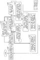
- FIG. 12 illustrates a method for reducing the effects of a noise source. Three processes are illustrated, and are referred to as "Process 1", “Process 2", and “Process 3".
- a first step 1202 achieve (acquire) one sample from the reference microphone (s[n]).
- step 1204 subtract the EC output [Ey[n] from s[n] to achieve x[n].
- the first two steps 1202 and 1204 are common to all three processes (Process 1, Process 2, Process 3).
- Process 1 loop back to the step 1202 to achieve another sample from the reference microphone.
- step 1210 compute the EC output (Ey[n]) by convolving y[n] with the EC coefficients (FIR filter), and provide the result to step 1204, as shown.
- the purpose of this step is to estimate and to subtract the destructive noise that is sensed by the reference microphone as a surplus signal.
- the optimal situation is that the reference microphone senses the source signal only, but the real situation is sensing the destructive signal from the speaker also.
- Process 3 is different than either of Process 1 or Process 2 in that it does not loop back.
- Process 3 after the step 1204, in a step 1212, compute the correct EC coefficients according to the LMS formula, as known in the literature.
- the purpose of this step is to Track changes in time in the transfer function of the speaker and of the space between the speaker and the reference microphone.
- Process 3 also after the step 1204, in a step 1214, compute the estimated error noise (mt[n]) by convolving x[n] with the MTF coefficients (FIR filter). Then, in a step 1216, add mt[n] to st[n] to have the estimated residual noise in the error microphone err[n]. Then, in a step 1218, compute the correct PF coefficients according to the LMS formula, as known in the literature. The purpose of these steps is to Track changes in time in the noise signal characteristic and hence to adjust the required destructive noise.
- Process 3 after the step 1206, in a step 1220, compute the estimated counter noise (st[n]) by convolving s[n] with the STF coefficients (FIR filter). Then, perform the step 1216, as already described.
- the purpose of these steps is to compute the correction of the PF coefficients as per the well known in the literature XLMS algorithm.
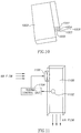
- FIG. 11 illustrates a thermal control unit.
- a thermostat 1102 may be provided in the duct 1100, and a thermal control unit 1104 may be used to control the speed of a fan/blower 1106, to regulate air temperature.
- the duct 1100 may be similar to the ducts 624, 900, 1002, 1004, 1006 described hereinabove.
- the thermal control unit 1104 may be integrated in the control system 636.
- FIG. 13 is a flow chart of a method for thermal control.
- a signal is acquired (step 1302) from the thermostat 1102 which is indicative of the temperature within the cabinet (such as 600).
- An appropriate speed for the fan 1106 is computed (step 1304) according to the temperature level, and it is set (step 1306).
- the fan speed is controlled in response to a climactic condition within the rack - in this example, temperature.
Landscapes
- Engineering & Computer Science (AREA)
- Physics & Mathematics (AREA)
- Acoustics & Sound (AREA)
- Multimedia (AREA)
- Computer Hardware Design (AREA)
- General Engineering & Computer Science (AREA)
- Thermal Sciences (AREA)
- Microelectronics & Electronic Packaging (AREA)
- Soundproofing, Sound Blocking, And Sound Damping (AREA)
- Cooling Or The Like Of Electrical Apparatus (AREA)
- Duct Arrangements (AREA)
Claims (8)
- Bâti (600) configuré pour maintenir une pluralité d'appareils électroniques (630), un appareil électronique (630) possédant une entrée pour recevoir de l'air pour le refroidissement des appareils électroniques, et une sortie pour l'évacuation de l'air, et le bâti (600) étant configuré pour maintenir l'appareil électronique (630) de sorte que l'entrée de l'appareil soit tournée dans une première direction et la sortie de l'appareil soit tournée dans une deuxième direction, le bâti (600) comprenant :
une partie antérieure (620) configurée pour maintenir la pluralité d'appareils électroniques (630), la partie antérieure (620) comprenant :une porte antérieure (602) possédant une entrée d'air (610) dans une partie inférieure du bâti (600), etun canal en labyrinthe (616) configuré pour assurer une fourniture d'air de l'entrée d'air (610) vers des entrées des appareils électroniques (630), le canal en labyrinthe (616) s'étendant de l'entrée d'air (610) dans une direction vers l'arrière du bâti (600), et tournant ensuite de 180 degrés pour s'étendre dans une direction vers l'avant du bâti (600) ; et une partie postérieure (624) configurée comme un panneau d'insonorisation climatisé, la partie postérieure (624) étant séparée de la partie antérieure (620) par une cloison intérieure (622) dotée d'une ouverture (628), et une soufflante contribuant au déplacement de l'air, par le biais de l'ouverture (628), de la partie antérieure (620) à la partie postérieure (624), la partie postérieure (624) comprenant :une porte postérieure (604) dotée d'une sortie d'air (618) dans une partie inférieure du bâti (600) pour le refoulement de l'air hors du bâti (600),un canal (640) s'étendant de l'ouverture (628) dans la cloison intérieure (622) à la sortie d'air (618), etun système de suppression active du bruit (ANC) configuré pour réduire le bruit à travers la partie postérieure (624), le système ANC comprenant :un microphone (706) situé au sein de ladite partie postérieure (624) pour détecter un profil de bruit et produire un signal sonore correspondant au profil de bruit détecté ;un haut-parleur (708) ; etun régulateur (710) configuré pour assurer la régulation du haut-parleur (708) pour produire un profil d'insonorisation conforme à un signal de régulation, le régulateur (710) comprenant :un suppresseur d'écho configuré pour produire un signal de suppression d'écho en convolutionnant un échantillon dudit signal de régulation avec des coefficients de suppression d'écho ;un soustracteur configuré pour produire un échantillon à écho supprimé en soustrayant la sortie de suppression d'écho d'un échantillon de bruit du profil de bruit détecté reçu du microphone ; etun filtre prédictif configuré pour produire un échantillon successif du signal de régulation en convolutionnant l'échantillon à écho supprimé avec des coefficients ajustables de filtres prédictifs, les coefficients de filtres prédictifs étant actualisés sur la base d'un bruit résiduel estimé à un microphone d'erreur. - Bâti selon la revendication 1, le régulateur (710) étant configuré en outre pour déterminer le bruit résiduel estimé sur la base d'une somme d'un résultat de la première convolution et d'un résultat de la deuxième convolution, ledit régulateur (710) étant configuré en outre pour déterminer ledit résultat de la première convolution en convolutionnant l'échantillon à écho supprimé avec une fonction de transfert d'un microphone de référence à un microphone d'erreur, et pour déterminer ledit résultat de la deuxième convolution en convolutionnant l'échantillon dudit signal de régulation avec une fonction de transfert d'un haut-parleur à un microphone d'erreur.
- Bâti selon la revendication 1 ou 2, ladite partie postérieure (624) comprenant au moins des premier et deuxième conduits pour le déplacement d'air depuis la partie antérieure (620), ledit premier conduit comprenant un premier système ANC, et ledit deuxième conduit comprenant un deuxième système ANC.
- Bâti selon la revendication 3, chacun desdits premier et deuxième conduits comprenant une entrée pour recevoir de l'air depuis la partie antérieure (620), et une sortie pour l'évacuation de l'air.
- Bâti selon la revendication 3 ou 4, ledit premier système ANC comprenant un premier microphone et un premier haut-parleur positionnés au sein dudit premier conduit, et ledit deuxième système ANC comprenant un deuxième microphone et un deuxième haut-parleur positionnés au sein dudit deuxième conduit.
- Bâti selon une quelconque des revendications 3 à 5, ledit premier conduit comprenant une première soufflante, et ledit deuxième conduit comprenant une deuxième soufflante.
- Bâti selon une quelconque des revendications 1 à 6, comprenant un régulateur de soufflante (1104) pour assurer la régulation d'une vitesse de la / des soufflante(s) en fonction de la température ambiante au sein dudit bâti (600).
- Bâti selon une quelconque des revendications 1 à 7, les appareils électroniques (630) comprenant au moins un serveur.
Applications Claiming Priority (6)
| Application Number | Priority Date | Filing Date | Title |
|---|---|---|---|
| US10/573,060 US7853024B2 (en) | 1997-08-14 | 2004-09-19 | Active noise control system and method |
| US77809006P | 2006-03-02 | 2006-03-02 | |
| US77809106P | 2006-03-02 | 2006-03-02 | |
| US11/606,010 US7869607B2 (en) | 2006-03-02 | 2006-11-30 | Quiet active fan for servers chassis |
| US11/606,019 US7783055B2 (en) | 1998-07-22 | 2006-11-30 | Soundproof climate controlled rack |
| PCT/IL2007/000270 WO2007099542A2 (fr) | 2006-03-02 | 2007-03-01 | Châssis insonorisé à régulation d'ambiance |
Publications (3)
| Publication Number | Publication Date |
|---|---|
| EP1993496A2 EP1993496A2 (fr) | 2008-11-26 |
| EP1993496A4 EP1993496A4 (fr) | 2013-04-03 |
| EP1993496B1 true EP1993496B1 (fr) | 2020-09-09 |
Family
ID=38459431
Family Applications (1)
| Application Number | Title | Priority Date | Filing Date |
|---|---|---|---|
| EP07713291.8A Active EP1993496B1 (fr) | 2006-03-02 | 2007-03-01 | Châssis insonorisé à régulation d'ambiance |
Country Status (2)
| Country | Link |
|---|---|
| EP (1) | EP1993496B1 (fr) |
| WO (1) | WO2007099542A2 (fr) |
Families Citing this family (24)
| Publication number | Priority date | Publication date | Assignee | Title |
|---|---|---|---|---|
| TWI473555B (zh) * | 2007-04-17 | 2015-02-11 | Fujitsu Ltd | 用於電子裝置之儲存盒 |
| DE102008011009A1 (de) | 2008-02-25 | 2009-08-27 | Rittal Gmbh & Co. Kg | Schaltschrank |
| DE102008011012B4 (de) | 2008-02-25 | 2011-06-16 | Rittal Gmbh & Co. Kg | Schaltschrank |
| FR2931962B1 (fr) * | 2008-06-02 | 2016-05-13 | Bull Sas | Dispositif de refroidissement adaptatif d'une baie informatique et baie informatique comportant un tel dispositif |
| GB2505716A (en) * | 2012-09-11 | 2014-03-12 | Ibm | Substantially closed loop air-cooler module for use with a computer or electronics rack. |
| US10045457B1 (en) | 2017-03-16 | 2018-08-07 | International Business Machines Corporation | System for maintaining the environment of a self-cooled data storage library |
| US10551806B2 (en) | 2017-03-16 | 2020-02-04 | International Business Machines Corporation | System for providing an access area for a data storage library |
| US10395695B2 (en) | 2017-03-16 | 2019-08-27 | International Business Machines Corporation | Data storage library with media acclimation device and methods of acclimating data storage media |
| US10026445B1 (en) | 2017-03-16 | 2018-07-17 | International Business Machines Corporation | Data storage library with interior access regulation |
| US10431254B2 (en) | 2017-03-16 | 2019-10-01 | International Business Machines Corporation | System for providing an acclimation enclosure for a data storage library |
| US10418071B2 (en) | 2017-03-16 | 2019-09-17 | International Business Machines Corporation | Data storage library with positive pressure system |
| US10890955B2 (en) | 2017-03-16 | 2021-01-12 | International Business Machines Corporation | System for controlling environmental conditions within an automated data storage library |
| US10660240B2 (en) | 2017-03-16 | 2020-05-19 | International Business Machines Corporation | Method for providing an access area for a data storage library |
| US9916869B1 (en) | 2017-03-16 | 2018-03-13 | International Business Machines Corporation | Method for servicing a self-cooled data storage library |
| US11500430B2 (en) | 2017-03-16 | 2022-11-15 | International Business Machines Corporation | Data storage library with service mode for protecting data storage drives |
| US10417851B2 (en) | 2017-03-16 | 2019-09-17 | International Business Machines Corporation | Data storage library with service mode |
| US10026455B1 (en) | 2017-03-16 | 2018-07-17 | International Business Machines Corporation | System and method for controlling environmental conditions within an automated data storage library |
| US10566023B2 (en) | 2017-03-16 | 2020-02-18 | International Business Machines Corporation | Data storage library with service mode for protecting data storage drives |
| US9940976B1 (en) | 2017-03-16 | 2018-04-10 | International Business Machines Corporation | Data storage library with component locker for environmental acclimation |
| US10303376B2 (en) | 2017-03-16 | 2019-05-28 | International Business Machines Corporation | Data storage library with pass-through connected media acclimation chamber |
| US9916871B1 (en) | 2017-03-16 | 2018-03-13 | International Business Machines Corporation | Data storage library with acclimation chamber |
| US10509421B2 (en) | 2017-03-16 | 2019-12-17 | International Business Machines Corproation | Method for controlling environmental conditions within an automated data storage library |
| CN109068523B (zh) * | 2018-07-03 | 2024-03-08 | 深圳市德汇云服科技有限公司 | 一种刀片式计算机网络服务器 |
| CN111736644A (zh) * | 2020-05-29 | 2020-10-02 | 甘肃海创新能源科技有限公司 | 一种温室大棚远程可视化监控系统及方法 |
Family Cites Families (11)
| Publication number | Priority date | Publication date | Assignee | Title |
|---|---|---|---|---|
| US4665549A (en) * | 1985-12-18 | 1987-05-12 | Nelson Industries Inc. | Hybrid active silencer |
| US5511127A (en) * | 1991-04-05 | 1996-04-23 | Applied Acoustic Research | Active noise control |
| US5377275A (en) * | 1992-07-29 | 1994-12-27 | Kabushiki Kaisha Toshiba | Active noise control apparatus |
| JPH07104890A (ja) | 1993-10-01 | 1995-04-21 | Fujitsu Ltd | 騒音低減装置 |
| US5606622A (en) * | 1994-09-29 | 1997-02-25 | The Boeing Company | Active noise control in a duct with highly turbulent airflow |
| JPH09274489A (ja) * | 1996-04-04 | 1997-10-21 | Canon Inc | 騒音低減装置 |
| US6459578B1 (en) * | 2001-04-24 | 2002-10-01 | Agilent Technologies, Inc. | Chassis having reduced acoustic noise and electromagnetic emissions and method of cooling components within a chassis |
| CA2361970A1 (fr) * | 2001-11-14 | 2003-05-14 | Catena Networks Canada Inc. | Systeme et methode de refroidissement passif d'une armoire |
| US7139401B2 (en) * | 2002-01-03 | 2006-11-21 | Hitachi Global Storage Technologies B.V. | Hard disk drive with self-contained active acoustic noise reduction |
| US6891347B2 (en) | 2002-10-09 | 2005-05-10 | Hewlett-Packard Development Company, L.P. | Cooling fan control based on cabinet intrusion |
| US7353908B1 (en) * | 2004-09-21 | 2008-04-08 | Emc Corporation | Method and system for attenuating noise from a cabinet housing computer equipment |
-
2007
- 2007-03-01 EP EP07713291.8A patent/EP1993496B1/fr active Active
- 2007-03-01 WO PCT/IL2007/000270 patent/WO2007099542A2/fr not_active Ceased
Non-Patent Citations (1)
| Title |
|---|
| None * |
Also Published As
| Publication number | Publication date |
|---|---|
| WO2007099542A3 (fr) | 2009-04-16 |
| EP1993496A4 (fr) | 2013-04-03 |
| EP1993496A2 (fr) | 2008-11-26 |
| WO2007099542A2 (fr) | 2007-09-07 |
Similar Documents
| Publication | Publication Date | Title |
|---|---|---|
| US7783055B2 (en) | Soundproof climate controlled rack | |
| EP1993496A2 (fr) | Châssis insonorisé à régulation d'ambiance | |
| US20110123036A1 (en) | Muffled rack and methods thereof | |
| US7869607B2 (en) | Quiet active fan for servers chassis | |
| EP0760115B1 (fr) | Ordinateur a refroidissement par air silencieux | |
| US7353908B1 (en) | Method and system for attenuating noise from a cabinet housing computer equipment | |
| AU2011234176B2 (en) | Acoustic dampening sleeve for electronic equipment and method of making the same | |
| CN100476690C (zh) | 减小有通气盖的计算机系统中的噪声的方法和装置 | |
| US20090268391A1 (en) | Disk array device and electronic device | |
| US10403328B2 (en) | Acoustic attenuation in data storage enclosures | |
| EP1566087B1 (fr) | Procede et dispositif de refroidissement combine par air et par liquide pour empilements de modules electroniques | |
| CN108464064B (zh) | 带有隔音的回流止动器 | |
| US7727059B2 (en) | Method and apparatus for acoustic noise reduction in a computer system having a vented door including a pivotable vented base and a pivotable outer door | |
| US8028793B2 (en) | Noise attenuating inserts for electronic equipment cabinets | |
| US10037061B1 (en) | Multiple-stage cooling system for rack | |
| JPH07104890A (ja) | 騒音低減装置 | |
| EP1993495B1 (fr) | Ventilateur actif silencieux pour châssis de serveurs | |
| US20100258377A1 (en) | Acoustic cooling muffler for computing systems | |
| US10660223B2 (en) | Electronics rack door assembly with collapsible acoustical panel | |
| JP5342363B2 (ja) | 制御装置の実装構造 | |
| Gaunt | A design process for minimising cooling system noise levels in modular disk drive storage sub-systems | |
| RU2574608C2 (ru) | Шумоподавляющий корпус для электронного оборудования | |
| Gaunt | The acoustic design of a high package density raid storage sub system with redundant cooling | |
| US20200196478A1 (en) | Data storage enclosure acoustics |
Legal Events
| Date | Code | Title | Description |
|---|---|---|---|
| PUAI | Public reference made under article 153(3) epc to a published international application that has entered the european phase |
Free format text: ORIGINAL CODE: 0009012 |
|
| AK | Designated contracting states |
Kind code of ref document: A2 Designated state(s): AT BE BG CH CY CZ DE DK EE ES FI FR GB GR HU IE IS IT LI LT LU LV MC MT NL PL PT RO SE SI SK TR |
|
| AX | Request for extension of the european patent |
Extension state: AL BA HR MK RS |
|
| R17D | Deferred search report published (corrected) |
Effective date: 20090416 |
|
| RIC1 | Information provided on ipc code assigned before grant |
Ipc: A61F 11/06 20060101AFI20090615BHEP Ipc: G10K 11/16 20060101ALI20090615BHEP Ipc: H03B 29/00 20060101ALI20090615BHEP |
|
| 17P | Request for examination filed |
Effective date: 20091015 |
|
| RBV | Designated contracting states (corrected) |
Designated state(s): AT BE BG CH CY CZ DE DK EE ES FI FR GB GR HU IE IS IT LI LT LU LV MC MT NL PL PT RO SE SI SK TR |
|
| DAX | Request for extension of the european patent (deleted) | ||
| A4 | Supplementary search report drawn up and despatched |
Effective date: 20130228 |
|
| RIC1 | Information provided on ipc code assigned before grant |
Ipc: G10K 11/178 20060101AFI20130222BHEP Ipc: H05K 7/20 20060101ALI20130222BHEP |
|
| STAA | Information on the status of an ep patent application or granted ep patent |
Free format text: STATUS: EXAMINATION IS IN PROGRESS |
|
| 17Q | First examination report despatched |
Effective date: 20181030 |
|
| GRAP | Despatch of communication of intention to grant a patent |
Free format text: ORIGINAL CODE: EPIDOSNIGR1 |
|
| STAA | Information on the status of an ep patent application or granted ep patent |
Free format text: STATUS: GRANT OF PATENT IS INTENDED |
|
| INTG | Intention to grant announced |
Effective date: 20200212 |
|
| GRAS | Grant fee paid |
Free format text: ORIGINAL CODE: EPIDOSNIGR3 |
|
| GRAA | (expected) grant |
Free format text: ORIGINAL CODE: 0009210 |
|
| STAA | Information on the status of an ep patent application or granted ep patent |
Free format text: STATUS: THE PATENT HAS BEEN GRANTED |
|
| AK | Designated contracting states |
Kind code of ref document: B1 Designated state(s): AT BE BG CH CY CZ DE DK EE ES FI FR GB GR HU IE IS IT LI LT LU LV MC MT NL PL PT RO SE SI SK TR |
|
| REG | Reference to a national code |
Ref country code: GB Ref legal event code: FG4D |
|
| REG | Reference to a national code |
Ref country code: AT Ref legal event code: REF Ref document number: 1312569 Country of ref document: AT Kind code of ref document: T Effective date: 20200915 Ref country code: CH Ref legal event code: EP |
|
| REG | Reference to a national code |
Ref country code: IE Ref legal event code: FG4D |
|
| REG | Reference to a national code |
Ref country code: DE Ref legal event code: R096 Ref document number: 602007060621 Country of ref document: DE |
|
| REG | Reference to a national code |
Ref country code: LT Ref legal event code: MG4D |
|
| PG25 | Lapsed in a contracting state [announced via postgrant information from national office to epo] |
Ref country code: BG Free format text: LAPSE BECAUSE OF FAILURE TO SUBMIT A TRANSLATION OF THE DESCRIPTION OR TO PAY THE FEE WITHIN THE PRESCRIBED TIME-LIMIT Effective date: 20201209 Ref country code: FI Free format text: LAPSE BECAUSE OF FAILURE TO SUBMIT A TRANSLATION OF THE DESCRIPTION OR TO PAY THE FEE WITHIN THE PRESCRIBED TIME-LIMIT Effective date: 20200909 Ref country code: GR Free format text: LAPSE BECAUSE OF FAILURE TO SUBMIT A TRANSLATION OF THE DESCRIPTION OR TO PAY THE FEE WITHIN THE PRESCRIBED TIME-LIMIT Effective date: 20201210 Ref country code: LT Free format text: LAPSE BECAUSE OF FAILURE TO SUBMIT A TRANSLATION OF THE DESCRIPTION OR TO PAY THE FEE WITHIN THE PRESCRIBED TIME-LIMIT Effective date: 20200909 Ref country code: SE Free format text: LAPSE BECAUSE OF FAILURE TO SUBMIT A TRANSLATION OF THE DESCRIPTION OR TO PAY THE FEE WITHIN THE PRESCRIBED TIME-LIMIT Effective date: 20200909 |
|
| REG | Reference to a national code |
Ref country code: AT Ref legal event code: MK05 Ref document number: 1312569 Country of ref document: AT Kind code of ref document: T Effective date: 20200909 |
|
| REG | Reference to a national code |
Ref country code: NL Ref legal event code: MP Effective date: 20200909 |
|
| PG25 | Lapsed in a contracting state [announced via postgrant information from national office to epo] |
Ref country code: LV Free format text: LAPSE BECAUSE OF FAILURE TO SUBMIT A TRANSLATION OF THE DESCRIPTION OR TO PAY THE FEE WITHIN THE PRESCRIBED TIME-LIMIT Effective date: 20200909 Ref country code: PL Free format text: LAPSE BECAUSE OF FAILURE TO SUBMIT A TRANSLATION OF THE DESCRIPTION OR TO PAY THE FEE WITHIN THE PRESCRIBED TIME-LIMIT Effective date: 20200909 |
|
| PG25 | Lapsed in a contracting state [announced via postgrant information from national office to epo] |
Ref country code: CZ Free format text: LAPSE BECAUSE OF FAILURE TO SUBMIT A TRANSLATION OF THE DESCRIPTION OR TO PAY THE FEE WITHIN THE PRESCRIBED TIME-LIMIT Effective date: 20200909 Ref country code: EE Free format text: LAPSE BECAUSE OF FAILURE TO SUBMIT A TRANSLATION OF THE DESCRIPTION OR TO PAY THE FEE WITHIN THE PRESCRIBED TIME-LIMIT Effective date: 20200909 Ref country code: RO Free format text: LAPSE BECAUSE OF FAILURE TO SUBMIT A TRANSLATION OF THE DESCRIPTION OR TO PAY THE FEE WITHIN THE PRESCRIBED TIME-LIMIT Effective date: 20200909 Ref country code: PT Free format text: LAPSE BECAUSE OF FAILURE TO SUBMIT A TRANSLATION OF THE DESCRIPTION OR TO PAY THE FEE WITHIN THE PRESCRIBED TIME-LIMIT Effective date: 20210111 Ref country code: NL Free format text: LAPSE BECAUSE OF FAILURE TO SUBMIT A TRANSLATION OF THE DESCRIPTION OR TO PAY THE FEE WITHIN THE PRESCRIBED TIME-LIMIT Effective date: 20200909 |
|
| PG25 | Lapsed in a contracting state [announced via postgrant information from national office to epo] |
Ref country code: AT Free format text: LAPSE BECAUSE OF FAILURE TO SUBMIT A TRANSLATION OF THE DESCRIPTION OR TO PAY THE FEE WITHIN THE PRESCRIBED TIME-LIMIT Effective date: 20200909 Ref country code: ES Free format text: LAPSE BECAUSE OF FAILURE TO SUBMIT A TRANSLATION OF THE DESCRIPTION OR TO PAY THE FEE WITHIN THE PRESCRIBED TIME-LIMIT Effective date: 20200909 Ref country code: IS Free format text: LAPSE BECAUSE OF FAILURE TO SUBMIT A TRANSLATION OF THE DESCRIPTION OR TO PAY THE FEE WITHIN THE PRESCRIBED TIME-LIMIT Effective date: 20210109 |
|
| REG | Reference to a national code |
Ref country code: DE Ref legal event code: R097 Ref document number: 602007060621 Country of ref document: DE |
|
| PG25 | Lapsed in a contracting state [announced via postgrant information from national office to epo] |
Ref country code: SK Free format text: LAPSE BECAUSE OF FAILURE TO SUBMIT A TRANSLATION OF THE DESCRIPTION OR TO PAY THE FEE WITHIN THE PRESCRIBED TIME-LIMIT Effective date: 20200909 |
|
| PLBE | No opposition filed within time limit |
Free format text: ORIGINAL CODE: 0009261 |
|
| STAA | Information on the status of an ep patent application or granted ep patent |
Free format text: STATUS: NO OPPOSITION FILED WITHIN TIME LIMIT |
|
| 26N | No opposition filed |
Effective date: 20210610 |
|
| PG25 | Lapsed in a contracting state [announced via postgrant information from national office to epo] |
Ref country code: DK Free format text: LAPSE BECAUSE OF FAILURE TO SUBMIT A TRANSLATION OF THE DESCRIPTION OR TO PAY THE FEE WITHIN THE PRESCRIBED TIME-LIMIT Effective date: 20200909 Ref country code: SI Free format text: LAPSE BECAUSE OF FAILURE TO SUBMIT A TRANSLATION OF THE DESCRIPTION OR TO PAY THE FEE WITHIN THE PRESCRIBED TIME-LIMIT Effective date: 20200909 |
|
| PG25 | Lapsed in a contracting state [announced via postgrant information from national office to epo] |
Ref country code: IT Free format text: LAPSE BECAUSE OF FAILURE TO SUBMIT A TRANSLATION OF THE DESCRIPTION OR TO PAY THE FEE WITHIN THE PRESCRIBED TIME-LIMIT Effective date: 20200909 Ref country code: MC Free format text: LAPSE BECAUSE OF FAILURE TO SUBMIT A TRANSLATION OF THE DESCRIPTION OR TO PAY THE FEE WITHIN THE PRESCRIBED TIME-LIMIT Effective date: 20200909 |
|
| REG | Reference to a national code |
Ref country code: CH Ref legal event code: PL |
|
| REG | Reference to a national code |
Ref country code: BE Ref legal event code: MM Effective date: 20210331 |
|
| PG25 | Lapsed in a contracting state [announced via postgrant information from national office to epo] |
Ref country code: IE Free format text: LAPSE BECAUSE OF NON-PAYMENT OF DUE FEES Effective date: 20210301 Ref country code: CH Free format text: LAPSE BECAUSE OF NON-PAYMENT OF DUE FEES Effective date: 20210331 Ref country code: LI Free format text: LAPSE BECAUSE OF NON-PAYMENT OF DUE FEES Effective date: 20210331 Ref country code: LU Free format text: LAPSE BECAUSE OF NON-PAYMENT OF DUE FEES Effective date: 20210301 |
|
| PG25 | Lapsed in a contracting state [announced via postgrant information from national office to epo] |
Ref country code: BE Free format text: LAPSE BECAUSE OF NON-PAYMENT OF DUE FEES Effective date: 20210331 |
|
| PG25 | Lapsed in a contracting state [announced via postgrant information from national office to epo] |
Ref country code: HU Free format text: LAPSE BECAUSE OF FAILURE TO SUBMIT A TRANSLATION OF THE DESCRIPTION OR TO PAY THE FEE WITHIN THE PRESCRIBED TIME-LIMIT; INVALID AB INITIO Effective date: 20070301 Ref country code: CY Free format text: LAPSE BECAUSE OF FAILURE TO SUBMIT A TRANSLATION OF THE DESCRIPTION OR TO PAY THE FEE WITHIN THE PRESCRIBED TIME-LIMIT Effective date: 20200909 |
|
| PG25 | Lapsed in a contracting state [announced via postgrant information from national office to epo] |
Ref country code: MT Free format text: LAPSE BECAUSE OF FAILURE TO SUBMIT A TRANSLATION OF THE DESCRIPTION OR TO PAY THE FEE WITHIN THE PRESCRIBED TIME-LIMIT Effective date: 20200909 |
|
| PGFP | Annual fee paid to national office [announced via postgrant information from national office to epo] |
Ref country code: DE Payment date: 20250320 Year of fee payment: 19 |
|
| PGFP | Annual fee paid to national office [announced via postgrant information from national office to epo] |
Ref country code: FR Payment date: 20250311 Year of fee payment: 19 |
|
| PGFP | Annual fee paid to national office [announced via postgrant information from national office to epo] |
Ref country code: GB Payment date: 20250218 Year of fee payment: 19 |
|
| PG25 | Lapsed in a contracting state [announced via postgrant information from national office to epo] |
Ref country code: TR Free format text: LAPSE BECAUSE OF FAILURE TO SUBMIT A TRANSLATION OF THE DESCRIPTION OR TO PAY THE FEE WITHIN THE PRESCRIBED TIME-LIMIT Effective date: 20200909 |