EP1993710B1 - Verzweigter radiofrequenz-multipol - Google Patents
Verzweigter radiofrequenz-multipol Download PDFInfo
- Publication number
- EP1993710B1 EP1993710B1 EP07752598A EP07752598A EP1993710B1 EP 1993710 B1 EP1993710 B1 EP 1993710B1 EP 07752598 A EP07752598 A EP 07752598A EP 07752598 A EP07752598 A EP 07752598A EP 1993710 B1 EP1993710 B1 EP 1993710B1
- Authority
- EP
- European Patent Office
- Prior art keywords
- ion
- branched
- radio frequency
- electrodes
- source
- Prior art date
- Legal status (The legal status is an assumption and is not a legal conclusion. Google has not performed a legal analysis and makes no representation as to the accuracy of the status listed.)
- Not-in-force
Links
- 230000005405 multipole Effects 0.000 title claims description 61
- 150000002500 ions Chemical class 0.000 claims description 181
- 102000004310 Ion Channels Human genes 0.000 claims description 82
- 238000000034 method Methods 0.000 claims description 23
- 238000004252 FT/ICR mass spectrometry Methods 0.000 claims description 8
- 238000000065 atmospheric pressure chemical ionisation Methods 0.000 claims description 6
- 238000000451 chemical ionisation Methods 0.000 claims description 6
- 238000001698 laser desorption ionisation Methods 0.000 claims description 6
- 238000005040 ion trap Methods 0.000 claims description 5
- 238000004949 mass spectrometry Methods 0.000 claims description 4
- 239000000463 material Substances 0.000 claims description 4
- 239000000126 substance Substances 0.000 claims description 4
- 238000003795 desorption Methods 0.000 claims description 3
- 238000010265 fast atom bombardment Methods 0.000 claims description 3
- 238000009616 inductively coupled plasma Methods 0.000 claims description 3
- 239000007788 liquid Substances 0.000 claims description 3
- 239000011159 matrix material Substances 0.000 claims description 3
- 230000005540 biological transmission Effects 0.000 claims description 2
- 238000001914 filtration Methods 0.000 claims 1
- 230000005684 electric field Effects 0.000 description 3
- 238000012986 modification Methods 0.000 description 3
- 230000004048 modification Effects 0.000 description 3
- 230000006978 adaptation Effects 0.000 description 2
- 238000013016 damping Methods 0.000 description 2
- 238000010586 diagram Methods 0.000 description 2
- 238000010884 ion-beam technique Methods 0.000 description 2
- 230000011218 segmentation Effects 0.000 description 2
- 230000001419 dependent effect Effects 0.000 description 1
- 230000005672 electromagnetic field Effects 0.000 description 1
- 238000000605 extraction Methods 0.000 description 1
- 238000007493 shaping process Methods 0.000 description 1
Images




Classifications
-
- H—ELECTRICITY
- H01—ELECTRIC ELEMENTS
- H01J—ELECTRIC DISCHARGE TUBES OR DISCHARGE LAMPS
- H01J49/00—Particle spectrometers or separator tubes
- H01J49/02—Details
- H01J49/06—Electron- or ion-optical arrangements
- H01J49/062—Ion guides
Definitions
- the invention is in the field of ion optics.
- Ion guides comprising four electrodes are used to transport ions from one place to another.
- mass spectrometry ion guides may be used to transport ions from an ion source to an ion analyzer.
- Some types of ion guides operate using radio frequency potentials applied to the four electrodes. Neighboring electrodes (orthogonal to each other) in the ion guide are operated at potentials of opposite polarity, while opposing electrodes in the ion guide are operated at the same potentials. The use of appropriate potentials results in the generation of a quadrupole field and an ion channel through which ions will preferentially travel. In some instances, such ion guides also operate as a mass filter or collision cell.
- US-A-2004/0026614 describes an ion guiding structure formed from stacked plate electrodes adapted to define curved ion channels. RF and (optional) DC voltages are applied to the plate electrodes to establish electromagnetic fields that condine ions to the ion channel.
- the ion guiding structures may have multiple inlets, and/or outlets and the structures may be operated to switch between inlets for ion beams from different sources or to switch an input ion beam between different exits to different detectors/analyzers.
- WO-A-2005/067000 discloses an arrangement for selective extraction, from an ion trap, of ions of a predetermined m/z or mobility. This is achieved by juxtaposing electrostatic and RF fields in a manner that separates ions spatially according to their m/z mobility.
- a system according to the invention includes a branched radio frequency multipole configured to act as an ion guide, as defined in claim 1.
- the branched radio frequency multipole comprises multiple ion channels through which ions can be alternatively directed.
- the branched radio frequency multipole is configured to control which of the multiple ion channels ions are directed, through the application of appropriate potentials. Thus, ions can alternatively be directed down different ion channels without the use of a mechanical valve.
- the branched radio frequency multipole is used to alternatively direct ions from one ion source to more than one alternative ion destination.
- the branched radio frequency multipole can be configured to direct an ion from an ion source to one of two alternative mass spectrometers.
- the branched radio frequency multipole is used to direct ions from alternative ion sources to a single ion destination.
- the branched radio frequency multipole can be configured to direct ions alternatively from an electron impact ion source and an atmospheric pressure ion source to a single mass spectrometer.
- the branched radio frequency multipole is used as a collision cell. In some embodiments, the branched radio frequency multipole is configured to act as a mass filter.
- the branched radio frequency multipole comprises at least a first branched electrode and a second branched electrode disposed parallel to each other, and a plurality of orthogonal electrodes disposed orthogonally to the first branched electrode and the second branched electrode.
- the branched electrodes and the orthogonal electrodes are configured to form an ion guide comprising at least a first ion channel and a second ion channel that diverge at a branch point.
- the first ion channel and the second ion channel overlap in part of the branched radio frequency multipole and diverge at the branch point.
- the system also comprises a radio frequency voltage source for applying radio frequency voltages to the first branched electrode, the second branched electrode, and the plurality of orthogonal electrodes.
- the amplitude and/or phase of the radio frequency voltages are selected for establishing a radio frequency potentials configured to form regions of ion stability in alternatively the first ion channel or the second ion channel and, thus, direct ions alternatively through the first ion channel or the second ion channel, respectively.
- the invention also extends to a method of using a branched radio frequency multipole as set out in claims 15 and 19.
- the method comprises setting voltages on segments of the branched electrodes and/or the orthogonal electrodes such that ions are directed down alternatively the first ion channel or the second ion channel.
- the invention includes a method of using a branched radio frequency multipole, the method comprising setting radio frequency voltages such that the radio frequency voltages opposite a first ion channel are different from the radio frequency voltages in a second ion channel.
- the method also comprises applying radio frequency voltages to orthogonal electrodes and branched electrodes in an opposite polarity alternating in time.
- the method also comprises introducing an ion from an ion source into the ion guide through an ion inlet and passing the ion to a first ion destination through the first ion channel.
- the method also comprises introducing a second ion from the ion source into the ion guide through an ion inlet and passing the second ion to a second ion destination through the second ion channel.
- FIG. 1 illustrates a perspective view of a branched radio frequency multipole system, according to various embodiments of the invention.
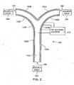
- FIG. 2 illustrates a top view of the branched radio frequency multipole system of FIG. 1 , having orthogonal electrodes split into segments, according to various embodiments of the invention.
- FIG. 3 illustrates a top view of a branched radio frequency multipole system, having branched electrodes split into segments, according to various embodiments of the invention.
- FIG. 4A illustrates a top view of a branched radio frequency multipole system, having a branched electrode split into segments, according to various embodiments of the invention.
- FIG. 4B illustrates a side view of the branched radio frequency multipole system of FIG. 4A , according to various embodiments of the invention.
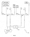
- FIG. 5 is a diagram of a circuit configured to supply radio frequency potentials to a branched radio frequency multipole system, according to various embodiments of the invention.
- FIG. 6 is a flowchart illustrating a method, according to various embodiments of the invention.
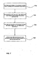
- FIG. 7 is a flowchart illustrating an alternative method, according to various embodiments of the invention.
- Preferred embodiments of the invention comprise a branched radio frequency multipole for guiding ions from a source toward alternative ion destinations, or from a plurality of ion sources to an ion destination. Preferred embodiments of the invention may also comprise two ion destinations or two ion sources.
- the branched radio frequency multipole comprises electrodes divided into segments, and is configured to guide ions through different ion channels by applying different radio frequency (RF) voltages to these segments.
- FIG. 1 illustrates a perspective view of a branched radio frequency multipole system, according to various embodiments of the invention.
- Branched radio frequency multipole system 100 comprises branched electrodes 110a and 110b, disposed parallel to each other.
- Branched radio frequency multipole system also comprises orthogonal electrodes 120A, 120B, 120C, 120D, 120E, 120F, 130A, and 130B.
- the orthogonal electrodes 120A-120F, 130A, and 130B are disposed orthogonally to the branched electrodes 11 OA and HOB such that the branched radio frequency multipole 100 comprises a first ion channel between ports 140 and 150 and a second ion channel between ports 140 and 160 of branched radio frequency multipole 100.
- Port 140 is an opening defined by the branched electrodes 11OA and HOB and the orthogonal electrodes 120A and 120D.
- Port 150 is an opening defined by the branched electrodes 110A and 110B and the orthogonal electrodes 120C and 130A.
- Port 160 is an opening defined by the branched electrodes 110A and 110B and the orthogonal electrodes 120F and 130B.
- the first ion channel and the second ion channel overlap in part of the branched radio frequency multipole 100 adjacent to port 140 and diverge at a branch point 170 before continuing to port 150 and port 160, respectively.
- the RF voltages applied to orthogonal electrodes 120B, 120C and 130A may be controlled such that the first ion channel comprising a path between port 140 and port 150 is opened.
- the RF voltages applied to orthogonal electrodes 120E, 120F, and 130B may be controlled such that the second ion channel comprising a path between port 140 and port 160 is opened.
- the paths by which ions traverse branched radio frequency multipole 100 can be controlled by the selection of appropriate voltages.
- FIG. 2 illustrates a top view of the branched radio frequency multipole system 100 of FIG. 1 , having orthogonal electrodes split into segments, according to various embodiments of the invention.
- the branched radio frequency multipole system 100 also comprises a radio frequency voltage source 210.
- Radio frequency voltage source 210 may be coupled to the orthogonal electrodes 120A, 120B, 120C, 120D, 120E, 120F, 130A, and 130B. Several, but not all, of these connections are shown in FIG. 2 .
- Radio frequency voltage source 210 may also be coupled to the branched electrodes, e.g. 110A and 110B.
- the RF voltages applied to orthogonal electrodes 120A-120F, 130A, 130B, and branched electrodes 110A and 110B may be controlled such that the first ion channel comprising a path between port 140 and port 150 is opened.
- the RF voltages applied to orthogonal electrodes 120A-120F, 130A and 130B may be controlled such that the RF voltage on orthogonal electrode 120E-120F and 130B is at least 1.1, 1.5, 2, or 3 times the RF voltage on orthogonal electrodes 120A-120Dand 130A.
- the RF voltages applied to orthogonal electrodes 120A-120F, 130A, 130B and branched electrodes 110A and 110B may be controlled such that the second ion channel comprising a path between port 140 and port 160 is opened.
- the RF voltages on orthogonal electrodes 120A-120F, 130A and 130B may be controlled such that the RF voltage on orthogonal electrode 120B-120C and 130A is at least 1.1, 1.5, 2, or 3 e times the RF voltage on orthogonal electrodes 120A, 120D-120F and 130B.
- the branched radio frequency multipole system 100 also comprises optional ion source/destinations 220, 230, and 240.
- Ion source/destination 220, ion source/destination 230, and ion source/destination 240 may each be an ion source and/or an ion destination.
- ion sources they may comprise, for example, an electron impact (EI) ion source, an electrospray (ESI) ion source, a matrix-assisted laser desorption (MALDI) ion source, a plasma source, an atmospheric pressure chemical ionization (APCI) ion source, a laser desorption ionization (LDI) ion source, an inductively coupled plasma (ICP) ion source, a chemical ionization (CI) ion source, a fast atom bombardment (FAB) ion source, an electron source, a liquid secondary ions mass spectrometry (LSMIS) source, or the like.
- EI electron impact
- ESI electrospray
- MALDI matrix-assisted laser desorption
- APCI atmospheric pressure chemical ionization
- LLI laser desorption ionization
- ICP inductively coupled plasma
- CI chemical ionization
- FAB fast atom bombardment
- FAB liquid secondary ions
- ion destinations they may comprise, for example, a mass filter, a chemical analyzer, material to be treated by the ion, a time of flight (TOF) mass analyzer, a quadrupole mass analyzer, a Fourier transform ion cyclotron resonance (FTICR) mass analyzer, a 2D (linear) quadrupole, a 3d quadrupole ion trap, a magnetic sector mass analyzer, a spectroscopic detector, a photomultiplier, a ion detector, an ion reaction chamber, or the like.
- TOF time of flight
- FTICR Fourier transform ion cyclotron resonance
- FIG. 3 illustrates a top view of the branched radio frequency multipole system 100, wherein branched electrodes 110A and 110B are each split into segments, according to various embodiments of the invention.
- branched electrode 110 and branched electrode 110B each include electrode segments 310A, 310B, and 310C.
- the electrode segments 310A, 310B, and 310C are disposed relative to each other such that a branched shape is formed.
- Branched radio frequency multipole system 100 also comprises orthogonal electrodes 320A, 320B, 330A, and 330B, disposed orthogonally to electrode segments 310A, 310B, and 310C.
- RF voltages applied to electrode segment 310C and orthogonal electrodes 320A, 320B, 330A, and 330B may be controlled such that ions are directed through the first ion channel between port 140 and port 150.
- an ion channel When an ion channel is open, those members of electrode segments 310A, 310B, and 310C that are adjacent to the open channel are normally operated at RF voltages having a polarity opposite of an RF voltage applied to the orthogonal electrodes 320A, 320B, 330A and 330B.
- this relationship between electrode segments of the branched electrodes and the orthogonal electrodes is not maintained, e.g. the same potentials may be applied to both a segment of the branched electrodes and the orthogonal electrodes.
- the RF voltage applied to electrode segment 310C may be to the same as the RF voltages applied to orthogonal electrodes 320A, 320B, 330A, and 330B.
- Setting the same potential on all four electrodes forming a branch of an ion channel allows the ion guide to reproduce an electric potential distribution closely analogous to a theoretical electric potential distribution if electrode segment 330A were continued following its curvature until it merged into electrode segment 320B.
- This configuration would be effectively equivalent, in terms of electric field distribution and ion transfer, to a regular curved four-electrode set. In this case, ions will successfully be passed through the first ion channel between port 140 and port 150, but will not traverse between port 160 and port 140.
- the RF voltages applied to electrode segment 310B and orthogonal electrodes 320A, 320B, 330A, and 330B may be the same. In this case, ions are directed through the second ion channel between-port 140 and port 160 and will not successfully pass between port 140 and port 150.
- FIG. 4A illustrates a top view of the branched radio frequency multipole system 100, wherein the branched electrodes 110 A and 110B are each split into segments, according to various embodiments of the invention.
- the branched electrode 110A is split into segments 410A, 410B, 410C, and 410D, which are disposed relative to each other such that a branched shape is formed.
- Orthogonal electrodes 420A, 420B, 430A, and 430B are disposed orthogonally to the electrode segments 410A, 410B, 410C, and 410D.
- Electrode segment 410B is typically maintained at the same RF voltages as electrode segment 410A.
- FIG. 4B illustrates a side view of the branched radio frequency multipole system 100 of FIG. 4A , according to various embodiments of the invention.
- This view shows that electrode segment 410B is displaced relative to electrode segment 410A.
- an inter-electrode distance 440 between the two instances of electrode segment 410B that make up part of branched electrode 110A and 110B ( FIG. 1 ) is greater than an inter-electrode distance 450 between the two instances of electrode segment 410A that make up part of branched electrode 110A and 110B.
- the inter-electrode distance 440 differs from the inter-electrode distance 450 by greater than 4, 8, 12 or 15 percent of inter-electrode distance 450.
- the embodiments of branched radio frequency multipole 100 illustrated by FIGs. 4A and 4B provide a greater control of the opening and closing of ion channels than the embodiments illustrated by FIG. 3 .
- the embodiments illustrated by FIGs. 4A and 4B allow for better shaping of the electric potential close to electrode 410B where the most significant distortion of electric field occurs because of electrode branching. This may result in better ion transmission efficiency in the open channel.
- electrode segments 410A and 410B are a single piece shaped to achieve the inter-electrode distances 440 and 450.
- FIG. 5 is a diagram of a circuit configured to supply radio frequency voltages to a branched radio frequency multipole system, according to various embodiments of the invention.
- Circuit 500 is optionally included in radio frequency voltage source 210.
- Circuit 500 comprises a phase switch 510, inductors 520, 530, 540, 550, 560, and 570, and an RF source 580.
- the phase of RF voltages on inductors 530 and 560 are dependent on the state of the phase switch 510. When phase switch 510 is OFF, both of these inductors will have the same RF voltages.
- phase switch 510 When phase switch 510 is ON, inductors 530 and 560 will have RF voltages of opposite polarity, e.g. be 180 degrees out of phase with each other.
- Inductors 520 and 540 respond to the inductance on inductor 530.
- Inductors 550 and 570 respond to the inductance on inductor 560.
- one of 410D (or 310C) and 410C (or 310B) will have the same polarity as 410A, 410B, while the other will have the opposite polarity. Ion channels will be opened and closed accordingly.
- this circuit 500 turning on and off the phase switch 510 can be used to open and close ion channels in the branched radio frequency multipole 100.
- FIG. 6 is a flowchart illustrating a method, according to various embodiments of the invention.
- electrode RF voltages are adjusted to alternatively pass ions to different destinations.
- a step 610 comprises setting electrode RF voltages such that the first ion channel between ports 140 and 150 of the branched radio frequency multipole 100 is opened to allow a first ion from an ion source, e.g. ion source/destination 220, to pass through the first ion channel toward a first ion destination, e.g. ion source/destination 230.
- a step 620 comprises introducing the first ion into the branched radio frequency multipole 100 and passing the first ion to the first ion destination.
- a step 630 comprises setting electrode RF voltages such that the second ion channel between ports 140 and 160 of the branched radio frequency multipole 100 is opened to allow a first ion from an ion source, e.g. ion source/destination 220, to pass through the first ion channel toward a second ion destination, e.g. ion source/destination 240.
- a step 640 comprises introducing the second ion into the branched radio frequency multipole 100 and passing the second ion to the second ion destination.
- FIG. 7 is a flowchart illustrating a method, according to various embodiments of the invention.
- electrode RF voltages are adjusted to alternatively pass ions to different destinations.
- a step 710 comprises setting electrode RF voltages such that the first ion channel between ports 140 and 150 of the branched radio frequency multipole 100 is opened to allow a first ion from a first ion source, e.g. ion source/destination 230, to pass through the first ion channel toward an ion-destination, e.g. ion source/destination 220.
- a step 720 comprises introducing the first ion into the branched radio frequency multipole 100 and passing the first ion to the ion destination.
- a step 730 comprises setting electrode RF voltages such that the second ion channel between ports 140 and 160 of the branched radio frequency multipole 100 is opened to allow a first ion from a second ion source, e.g. ion source/destination 240, to pass through the first ion channel toward the ion destination, e.g. ion source/destination 220.
- a step 740 comprises introducing the second ion into the branched radio frequency multipole 100 and passing the second ion to the ion destination.
- the branched electrodes discussed herein may be curved on sides facing toward the first ion channel and the second ion channel.
- the branched electrodes may be parabolic or round.
- branched radio frequency multipole 100 may be used as a collision cell or as a mass filter.
- the segmentation of the orthogonal electrodes illustrated in FIG. 2 can be used in combination with segmentation of the branched electrodes illustrated in FIGs. 3 , 4A , and 4B .
- Collision gas can be used to reduce significant excursion of ion trajectories from a center line of the ion guide because of collisional damping. This may simplify forming appropriate electric fields using a combination of electrode segments and associated voltages. For example, with collisional dampening, a spatial region that preferably approximates a standard curved four-electrode ion guide may be reduced to a narrow spatial region around the center line of ion trajectories, relative to a system without collisional damping.
Landscapes
- Chemical & Material Sciences (AREA)
- Analytical Chemistry (AREA)
- Other Investigation Or Analysis Of Materials By Electrical Means (AREA)
Claims (21)
- System (100), das Folgendes umfasst:eine erste verzweigte Elektrode (110A);eine zweite verzweigte Elektrode (110B);gekennzeichnet durch mehrere orthogonale Elektroden (120A-F; 130A-B; 320A-B; 330A-B; 420A-B; 430A-B), orthogonal zu der ersten verzweigten Elektrode (110A) und der zweiten verzweigten Elektrode (110B) angeordnet, wobei die erste verzweigte Elektrode (110A), die zweite verzweigte Elektrode (110B) und die mehreren orthogonalen Elektroden (120A-F; 130A-B; 320A-B; 330AB; 420A-B; 430A-B) konfiguriert sind, einen Ionenleiter auszubilden, der einen ersten Ionenkanal und einen zweiten Ionenkanal und einen Verzweigungspunkt (170) umfasst, wo der erste Ionenkanal und der zweite Ionenkanal divergieren; und
eine Hochfrequenzspannungsquelle (210) zum Anlegen von Hochfrequenzspannungen an die erste verzweigte Elektrode (110A), die zweite verzweigte Elektrode (110B) und die mehreren orthogonalen Elektroden (120A-F; 130A-B; 320A-B; 330A-B; 420A-B; 430A-B), wobei die Amplitude und/oder Phase der Hochfrequenzspannungen ausgewählt werden zum Herstellen eines Gebiets der Ionenübertragungsstabilität abwechselnd im ersten Ionenkanal oder im zweiten Ionenkanal und somit zum abwechselnden Lenken von Ionen durch den ersten Ionenkanal beziehungsweise den zweiten Ionenkanal. - System nach Anspruch 1, wobei die orthogonalen Elektroden (120A-F; 130A-B; 320A-B; 330A-B; 420A-B; 430A-B) jeweils unterteilt sind in mehrere Segmente (310A-C; 410A-D), und eine erste Teilmenge der mehreren Segmente (310A-C; 410A-D) der bei dem Verzweigungspunkt (170) angeordneten orthogonalen Elektroden (120A-F; 130A-B; 320A-B; 330A-B; 420A-B; 430A-B) konfiguriert ist, auf einer anderen Hochfrequenzspannung als eine zweite Teilmenge der mehreren Segmente (310A-C; 410A-D) der orthogonalen Elektroden (120A-F; 130A-B; 320A-B; 330A-B; 420A-B; 430A-B) gehalten zu werden.
- System (100) nach Anspruch 2, wobei eine Differenz bei der Hochfrequenzspannung zwischen der ersten Teilmenge der mehreren Segmente (310A-C; 410A-D) der orthogonalen Elektroden (120A-F; 130A-B; 320A-B; 330AB; 420A-B; 430A-B) und der zweiten Teilmenge der mehreren Segmente (310A-C, 410A-D) der orthogonalen Elektroden (120A-F; 130A-B; 320A-B; 330A-B; 420A-B; 430A-B) größer ist als ein Faktor von 1,1.
- System (100) nach Anspruch 1, wobei die erste verzweigte Elektrode (110A) und die zweite verzweigte Elektrode (110B) jeweils in mehrere Segmente (310A-C; 410A-D) unterteilt sind und
mindestens ein erstes Segment der mehreren Segmente (310A-C; 410A-D) konfiguriert ist, auf einer anderen Hochfrequenzspannung als ein zweites Segment der mehreren angeordneten Segmente (310A-C; 410A-D) gehalten zu werden. - System (100) nach Anspruch 4, wobei die orthogonalen Elektroden (120A-F; 130A-B; 320A-B; 330AB; 420A-B; 430A-B) konfiguriert sind als mehrere orthogonale Segmente (420A-B; 430A-B), wobei eine erste Teilmenge der mehreren bei dem Verzweigungspunkt (170) angeordneten orthogonalen Segmente konfiguriert ist, auf einer anderen Hochfrequenzspannung als eine zweite Teilmenge der mehreren orthogonalen Segmente (420A-B, 430A-B) gehalten zu werden.
- System (100) nach Anspruch 1, wobei die erste verzweigte Elektrode (110A) und die zweite verzweigte Elektrode (110B) jeweils als mehrere Segmente (310A-C; 410A-D) konfiguriert sind und ein Element der mehreren Segmente (310A-C; 410A-D) bei einem geschlossenen Ionenkanal konfiguriert ist, auf einer gleichen Hochfrequenzspannung wie ein Element der mehreren orthogonalen Elektroden (120A-F; 130A-B; 320A-B; 330AB; 420A-B; 430A-B) gehalten zu werden.
- System (100) nach Anspruch 1, wobei die erste verzweigte Elektrode und die zweite verzweigte Elektrode als mehrere Segmente (310A-C; 410A-D) konfiguriert sind und ein Abstand zwischen einem ersten Segment der ersten verzweigten Elektrode bei dem Verzweigungspunkt (170) und einem ersten Segment der zweiten verzweigten Elektrode bei dem Verzweigungspunkt (170) mindestens vier Prozent größer ist als ein Abstand zwischen einem zweiten Segment der ersten verzweigten Elektrode nicht bei dem Verzweigungspunkt (170) und einem entsprechenden zweiten Segment der zweiten verzweigten Elektrode nicht bei dem Verzweigungspunkt (170).
- System (100) nach Anspruch 1, wobei die gleichen Hochfrequenzspannungen verwendet werden, um abwechselnd den ersten Ionenkanal und den zweiten Ionenkanal zu öffnen, indem sie an verschiedene Elemente der ersten verzweigten Elektrode (110A), der zweiten verzweigten Elektrode (110B) oder Elemente der mehreren orthogonalen Elektroden (120A-F; 130A-B; 320A-B; 330AB; 420A-B; 430A-B) angelegt zu werden.
- System (100) nach Anspruch 1, wobei die Flächen der ersten verzweigten Elektrode (110A) und der zweiten verzweigten Elektrode (110B), dem ersten Ionenkanal zugewandt, gekrümmt sind.
- System (100) nach Anspruch 1, das weiterhin Folgendes umfasst:eine erste Ionenquelle (220), die konfiguriert ist, Ionen in den Ionenleiter einzuführen;eine erste Ionendestination (240), die konfiguriert ist, Ionen durch den ersten Ionenkanal zu empfangen.
- System (100) nach Anspruch 10, weiterhin umfassend eine zweite Ionendestination (260), die konfiguriert ist, Ionen von dem zweiten Ionenkanal oder einer zweiten Ionenquelle zu empfangen.
- System (100) nach Anspruch 11, wobei die erste oder zweite Ionendestination (240, 260) einen Massenfilter, einen chemischen Analysator, durch das Ion zu behandelndes Material, einen Flugzeit (TOF - Time of Flight)-Massenanalysator, einen Quadrupol-Massenanalysator, einen Fouriertransformations-Ionencyclotronresonanz (FTICR - Fourier Transform Ion Cyclotron Resonance)-Massenanalysator, einen 2D-(Linear-) Quadrupol, eine 3D-Quadrupolionenfalle, einen Magnetsektormassenanalysator, einen spektroskopischen Detektor, einen Fotoelektronenvervielfacher und/oder einen Ionendetektor enthält.
- System nach Anspruch 10, wobei die erste Ionenquelle (220) eine Elektronenstoß (EI)-Ionenquelle, eine Elektronenspray (ESI)-Ionenquelle, eine MALDI-Ionenquelle (Matrix-assisted Laser Desorption-Ionenquelle), eine Plasmaquelle, eine APCI-Ionenquelle (Atmospheric Pressure Chemical Ionization - chemische Ionisation bei Atmosphärendruck), eine Laserdesorptionsionisationsionenquelle (LDI - Laser Desorption Ionization), eine ICP-Ionenquelle (Inductively Coupled Plasma - induktiv gekoppeltes Plasma), eine chemische Ionisationsionenquelle (CI - Chemical Ionisation), eine FAB-Ionenquelle (Fast Atom Bombardment - schneller Atombeschuss), eine Elektronenquelle und/oder eine LSMIS-Quelle (Liquid Secondary Ions Mass Spectrometry-Quelle) enthält.
- System nach Anspruch 1, wobei die erste verzweigte Elektrode (110A) und die zweite verzweigte Elektrode (110B) jeweils so geformt sind, dass sich ein größerer Zwischenelektrodenabstand nahe dem Verzweigungspunkt (170) relativ zu einem Zwischenelektrodenabstand weiter weg von dem Verzweigungspunkt (170) ergibt.
- Verfahren zum Verwenden eines verzweigten Hochfrequenzmultipols (100), wobei das Verfahren Folgendes umfasst:Liefern erster Hochfrequenzspannungen an einen verzweigten Hochfrequenzmultipol, so dass ein erster Ionenkanal geöffnet wird und ein zweiter Ionenkanal geschlossen wird, wobei sich der erste Ionenkanal und der zweite Ionenkanal in einem Teil des verzweigten Hochfrequenzmultipols überlappen und bei einem Verzweigungspunkt (170) divergieren, wobei die ersten Hochfrequenzspannungen eine an mehrere verzweigte Elektroden (110A, 110B) angelegte erste Menge von Spannungen und eine an eine erste Mehrzahl von orthogonalen Elektroden (120A-D, 130A, 320A, 320B, 330A, 420A, 420B, 430A) orthogonal zu den mehreren verzweigten Elektroden (110A, 110B) angelegte zweite Menge von Spannungen enthalten, wobei die erste Menge von Spannungen um etwa 180 Grad außer Phase bezüglich der zweiten Menge von Spannungen ist;Einführen eines ersten Ions von einer Ionenquelle (220) in den verzweigten Hochfrequenzmultipol (100) durch einen Ioneneinlass (140) und Schicken des Ions zu einer ersten Ionendestination (230) durch den ersten Ionenkanal;Liefern zweiter Hochfrequenzspannungen an den verzweigten Hochfrequenzmultipol (100), so dass der erste Ionenkanal geschlossen ist und der zweite Ionenkanal offen ist, wobei die zweiten Hochfrequenzspannungen eine an die mehreren verzweigten Elektroden (110A, 110B) angelegte erste Menge von Spannungen und eine an eine zweite Mehrzahl von orthogonalen Elektroden (120A, 120D-F; 130A, 320B; 330B; 420A, 420B; 430B) orthogonal zu den mehreren verzweigten Elektroden (110A, 110B) angelegte zweite Menge von Spannungen beinhalten, wobei die erste Mehrzahl von orthogonalen Elektroden (120A-D, 130A; 320A, 320B, 330A; 420A, 420B, 430A) und die zweite Mehrzahl von orthogonalen Elektroden (102A, 120D-F; 320A; 320B; 420A; 420B; 430B) einige Elektroden (120A, 120D, 320A, 320B, 420A, 420B) gemeinsam haben, wobei sich die zweite Mehrzahl von orthogonalen Elektroden (120A, 120D-F, 320A, 320B, 420A, 420B; 430B) bei dem zweiten Ionenkanal befindet; undEinführen eines zweiten Ions von der Ionenquelle (220) in den verzweigten Hochfrequenzmultipol (100) durch einen Ioneneinlass (140) und Schicken des Ions zu einer zweiten Ionendestination (240) durch den zweiten Ionenkanal.
- Verfahren nach Anspruch 15, wobei die erste oder zweite Ionendestination (230, 240) einen Massenfilter, einen chemischen Analysator, durch das Ion zu behandelndes Material, einen Flugzeit (TOF - Time of Flight)-Massenanalysator, einen Quadrupol-Massenanalysator, einen Fouriertransformations-Ionencyclotronresonanz (FTICR - Fourier Transform Ion Cyclotron Resonance)-Massenanalysator, einen 2D- (Linear-) Quadrupol, eine 3D-Quadrupolionenfalle, einen Magnetsektormassenanalysator, einen spektroskopischen Detektor, einen Fotoelektronenvervielfacher und/oder einen Ionendetektor enthält.
- Verfahren nach Anspruch 15, wobei die erste Ionenquelle (220) eine Elektronenstoß (EI)-Ionenquelle, eine Elektronenspray (ESI)-Ionenquelle, eine MALDI-Ionenquelle (Matrix-assisted Laser Desorption-Ionenquelle), eine Plasmaquelle, eine APCI-Ionenquelle (Atmospheric Pressure Chemical Ionization - chemische Ionisation bei Atmosphärendruck), eine Laserdesorptionsionisationsionenquelle (LDI - Laser Desorption Ionization), eine ICP-Ionenquelle (Inductively Coupled Plasma - induktiv gekoppeltes Plasma), eine chemische Ionisationsionenquelle (CI - Chemical Ionisation), eine FAB-Ionenquelle (Fast Atom Bombardment - schneller Atombeschuss), eine Elektronenquelle und/oder eine LSMIS-Quelle (Liquid Secondary Ions Mass Spectrometry-Quelle) enthält.
- Verfahren nach Anspruch 15, weiterhin umfassend das Einleiten von Kollisionsgas in den verzweigten Hochfrequenzmultipol (100).
- Verfahren zum Verwenden eines verzweigten Hochfrequenzmultipols (100), wobei das Verfahren Folgendes umfasst:Liefern erster Hochfrequenzspannungen an einen verzweigten Hochfrequenzmultipol, so dass ein erster Ionenkanal geöffnet wird und ein zweiter Ionenkanal geschlossen wird, wobei sich der erste Ionenkanal und der zweite Ionenkanal in einem Teil des verzweigten Hochfrequenzmultipols überlappen und bei einem Verzweigungspunkt (170) divergieren, wobei die ersten Hochfrequenzspannungen eine an mehrere verzweigte Elektroden (110A, 110B) angelegte erste Menge von Spannungen und eine an eine erste Mehrzahl von orthogonalen Elektroden (120A-D, 130A, 320A, 320B, 330A, 420A, 420B, 430A) orthogonal zu den mehreren verzweigten Elektroden (110A, 110B) angelegte zweite Menge von Spannungen enthalten, wobei die erste Menge von Spannungen eine Polarität aufweist, die der der zweiten Menge von Spannungen entgegengesetzt ist;Einleiten eines ersten Ions von einer ersten Ionenquelle (230) in den Ionenleiter durch einen ersten Ioneneinlass (150) und Schicken des Ions zu einer Ionendestination durch den ersten Ionenkanal;Liefern zweiter Hochfrequenzspannungen an den verzweigten Hochfrequenzmultipol (100), so dass der erste Ionenkanal geschlossen ist und der zweite Ionenkanal offen ist, wobei die zweiten Hochfrequenzspannungen eine an die mehreren verzweigten Elektroden (110A, 110B) angelegte erste Menge von Spannungen und eine an eine zweite Mehrzahl von orthogonalen Elektroden (120A, 120D-120F; 320A, 320B; 330B; 420A, 420B; 430B) orthogonal zu den mehreren verzweigten Elektroden (110A, 110B) angelegte zweite Menge von Spannungen beinhalten, wobei die erste Mehrzahl von orthogonalen Elektroden (120A-D, 130A; 320A, 320B, 330A; 420A, 420B, 430A) und die zweite Mehrzahl von orthogonalen Elektroden (120A, 120D-120F; 320A; 320B; 330B; 420A; 420B; 430B) einige Elektroden (120A, 120D, 320A, 320B, 420A, 420B) gemeinsam haben, wobei sich die erste Mehrzahl von orthogonalen Elektroden (120A-D, 130A, 320A, 320B, 330A; 420A, 420B; 430A) bei dem ersten Ionenkanal befindet; undEinleiten eines zweiten Ions von einer zweiten Ionenquelle (240) in den verzweigten Hochfrequenzmultipol durch einen zweiten Ioneneinlass (140) und Schicken des Ions an die Ionendestination (220) durch den zweiten Ionenkanal.
- Verfahren nach Anspruch 19, wobei die Ionendestination (220) einen Massenfilter, einen chemischen Analysator, durch das Ion zu behandelndes Material, einen Flugzeit (TOF - Time of Flight)-Massenanalysator, einen Quadrupol-Massenanalysator, einen Fouriertransformations-Ionencyclotronresonanz (FTICR - Fourier Transform Ion Cyclotron Resonance)-Massenanalysator, einen 2D- (Linear-) Quadrupol, eine 3D-Quadrupolionenfalle, einen Magnetsektormassenanalysator, einen spektroskopischen Detektor, einen Fotoelektronenvervielfacher und/oder einen Ionendetektor enthält.
- Verfahren nach Anspruch 19, weiterhin umfassend das Filtern des ersten Ions innerhalb des verzweigten Hochfrequenzmultipols (100) als eine Funktion des Masse-Ladungs-Verhältnisses.
Applications Claiming Priority (2)
| Application Number | Priority Date | Filing Date | Title |
|---|---|---|---|
| US11/373,354 US7420161B2 (en) | 2006-03-09 | 2006-03-09 | Branched radio frequency multipole |
| PCT/US2007/005910 WO2007103489A2 (en) | 2006-03-09 | 2007-03-07 | Branched radio frequency multipole |
Publications (3)
| Publication Number | Publication Date |
|---|---|
| EP1993710A2 EP1993710A2 (de) | 2008-11-26 |
| EP1993710A4 EP1993710A4 (de) | 2009-11-04 |
| EP1993710B1 true EP1993710B1 (de) | 2012-12-12 |
Family
ID=38475555
Family Applications (1)
| Application Number | Title | Priority Date | Filing Date |
|---|---|---|---|
| EP07752598A Not-in-force EP1993710B1 (de) | 2006-03-09 | 2007-03-07 | Verzweigter radiofrequenz-multipol |
Country Status (4)
| Country | Link |
|---|---|
| US (1) | US7420161B2 (de) |
| EP (1) | EP1993710B1 (de) |
| CA (1) | CA2662828C (de) |
| WO (1) | WO2007103489A2 (de) |
Families Citing this family (26)
| Publication number | Priority date | Publication date | Assignee | Title |
|---|---|---|---|---|
| US7829850B2 (en) * | 2006-03-09 | 2010-11-09 | Thermo Finnigan Llc | Branched radio frequency multipole |
| US7420161B2 (en) * | 2006-03-09 | 2008-09-02 | Thermo Finnigan Llc | Branched radio frequency multipole |
| JP4883176B2 (ja) * | 2007-05-09 | 2012-02-22 | 株式会社島津製作所 | 荷電粒子分析装置 |
| US20090090853A1 (en) * | 2007-10-05 | 2009-04-09 | Schoen Alan E | Hybrid mass spectrometer with branched ion path and switch |
| JP5003508B2 (ja) * | 2008-01-24 | 2012-08-15 | 株式会社島津製作所 | 質量分析システム |
| US8426805B2 (en) * | 2008-02-05 | 2013-04-23 | Thermo Finnigan Llc | Method and apparatus for response and tune locking of a mass spectrometer |
| US7952070B2 (en) * | 2009-01-12 | 2011-05-31 | Thermo Finnigan Llc | Interlaced Y multipole |
| GB2484136B (en) | 2010-10-01 | 2015-09-16 | Thermo Fisher Scient Bremen | Method and apparatus for improving the throughput of a charged particle analysis system |
| JP5686566B2 (ja) * | 2010-10-08 | 2015-03-18 | 株式会社日立ハイテクノロジーズ | 質量分析装置 |
| US8314385B2 (en) * | 2011-04-19 | 2012-11-20 | Bruker Daltonics, Inc. | System and method to eliminate radio frequency coupling between components in mass spectrometers |
| US8421007B2 (en) * | 2011-05-18 | 2013-04-16 | Tohoku University | X-ray detection system |
| DE102011108691B4 (de) | 2011-07-27 | 2014-05-15 | Bruker Daltonik Gmbh | Seitliche Einführung von Ionen in Hochfrequenz-Ionenleitsysteme |
| US10521411B2 (en) | 2016-08-10 | 2019-12-31 | Moonshadow Mobile, Inc. | Systems, methods, and data structures for high-speed searching or filtering of large datasets |
| US20180323050A1 (en) | 2017-05-05 | 2018-11-08 | Thermo Finnigan Llc | Ion integrating and cooling cell for mass spectrometer |
| GB2563077A (en) | 2017-06-02 | 2018-12-05 | Thermo Fisher Scient Bremen Gmbh | Mass error correction due to thermal drift in a time of flight mass spectrometer |
| EP3410463B1 (de) | 2017-06-02 | 2021-07-28 | Thermo Fisher Scientific (Bremen) GmbH | Hybrides massenspektrometer |
| GB2600985B (en) | 2020-11-16 | 2024-10-30 | Thermo Fisher Scient Bremen Gmbh | Mass spectrometer and method of mass spectrometry |
| WO2022189924A1 (en) * | 2021-03-08 | 2022-09-15 | Dh Technologies Development Pte. Ltd. | Bifurcated mass spectrometer |
| CN114914151B (zh) * | 2022-05-25 | 2025-05-27 | 安益谱(苏州)医疗科技有限公司 | 一种离子导引技术 |
| CN115083883A (zh) * | 2022-08-04 | 2022-09-20 | 广州禾信仪器股份有限公司 | 一种离子传输装置及离子传输方法 |
| CN115579276A (zh) * | 2022-09-18 | 2023-01-06 | 杭州谱育科技发展有限公司 | 基于多种分析技术的质谱分析系统和方法 |
| US20240274425A1 (en) | 2023-02-15 | 2024-08-15 | Thermo Finnigan Llc | Mass spectrometer and data acquisition methods for identification of positive and negative analyte ions |
| GB2627217A (en) | 2023-02-15 | 2024-08-21 | Thermo Fisher Scient Bremen Gmbh | Hybrid mass spectrometer and data aquisition methods |
| WO2025137365A1 (en) * | 2023-12-22 | 2025-06-26 | Peninsula Technologies, Llc | Systems and methods for ion switch mass spectrometry |
| GB2637007B (en) * | 2024-01-03 | 2026-03-18 | Thermo Fisher Scient Bremen Gmbh | Methods of mass spectrometry, a mass spectrometer and computer software |
| GB202415335D0 (en) | 2024-10-18 | 2024-12-04 | Thermo Fisher Scient Bremen Gmbh | Ion routing device |
Family Cites Families (21)
| Publication number | Priority date | Publication date | Assignee | Title |
|---|---|---|---|---|
| US3648046A (en) * | 1970-05-18 | 1972-03-07 | Granville Phillips Co | Quadrupole gas analyzer comprising four flat plate electrodes |
| DE4324224C1 (de) * | 1993-07-20 | 1994-10-06 | Bruker Franzen Analytik Gmbh | Quadrupol-Ionenfallen mit schaltbaren Multipol-Anteilen |
| US5436919A (en) * | 1994-01-25 | 1995-07-25 | Eastman Kodak Company | Multiwavelength upconversion waveguide laser |
| US6011259A (en) * | 1995-08-10 | 2000-01-04 | Analytica Of Branford, Inc. | Multipole ion guide ion trap mass spectrometry with MS/MSN analysis |
| US5920562A (en) * | 1996-11-22 | 1999-07-06 | Sprint Communications Co. L.P. | Systems and methods for providing enhanced services for telecommunication call |
| DE19629134C1 (de) * | 1996-07-19 | 1997-12-11 | Bruker Franzen Analytik Gmbh | Vorrichtung zur Überführung von Ionen und mit dieser durchgeführtes Meßverfahren |
| JP2921500B2 (ja) * | 1996-07-30 | 1999-07-19 | 日本電気株式会社 | イオン注入装置 |
| US6593570B2 (en) * | 2000-05-24 | 2003-07-15 | Agilent Technologies, Inc. | Ion optic components for mass spectrometers |
| JP3730527B2 (ja) * | 2001-03-06 | 2006-01-05 | 株式会社日立製作所 | 質量分析装置 |
| US6891157B2 (en) * | 2002-05-31 | 2005-05-10 | Micromass Uk Limited | Mass spectrometer |
| AU2003260773A1 (en) | 2002-09-03 | 2004-03-29 | Micromass Uk Limited | Mass spectrometer |
| JP3931866B2 (ja) * | 2002-10-23 | 2007-06-20 | 株式会社村田製作所 | 表面実装型アンテナおよびそれを用いたアンテナ装置および通信装置 |
| CN101685755B (zh) * | 2003-01-24 | 2011-12-14 | 萨莫芬尼根有限责任公司 | 控制质量分析器中的离子数目 |
| US7019289B2 (en) * | 2003-01-31 | 2006-03-28 | Yang Wang | Ion trap mass spectrometry |
| US7157698B2 (en) * | 2003-03-19 | 2007-01-02 | Thermo Finnigan, Llc | Obtaining tandem mass spectrometry data for multiple parent ions in an ion population |
| US6967340B2 (en) * | 2003-08-19 | 2005-11-22 | Alps Electric Co., Ltd. | Ion beam irradiation device and operating method thereof |
| ATE507576T1 (de) * | 2004-01-09 | 2011-05-15 | Micromass Ltd | Ionenextraktionseinrichtungen und verfahren zur selektiven extraktion von ionen |
| DE102004028419B4 (de) * | 2004-06-11 | 2011-06-22 | Bruker Daltonik GmbH, 28359 | Massenspektrometer und Reaktionszelle für Ionen-Ionen-Reaktionen |
| GB0424426D0 (en) * | 2004-11-04 | 2004-12-08 | Micromass Ltd | Mass spectrometer |
| US7358488B2 (en) * | 2005-09-12 | 2008-04-15 | Mds Inc. | Mass spectrometer multiple device interface for parallel configuration of multiple devices |
| US7420161B2 (en) * | 2006-03-09 | 2008-09-02 | Thermo Finnigan Llc | Branched radio frequency multipole |
-
2006
- 2006-03-09 US US11/373,354 patent/US7420161B2/en active Active
-
2007
- 2007-03-07 CA CA2662828A patent/CA2662828C/en not_active Expired - Fee Related
- 2007-03-07 EP EP07752598A patent/EP1993710B1/de not_active Not-in-force
- 2007-03-07 WO PCT/US2007/005910 patent/WO2007103489A2/en not_active Ceased
Also Published As
| Publication number | Publication date |
|---|---|
| WO2007103489A2 (en) | 2007-09-13 |
| EP1993710A4 (de) | 2009-11-04 |
| EP1993710A2 (de) | 2008-11-26 |
| US7420161B2 (en) | 2008-09-02 |
| WO2007103489A3 (en) | 2008-04-17 |
| CA2662828C (en) | 2014-01-21 |
| CA2662828A1 (en) | 2007-09-13 |
| US20080061227A1 (en) | 2008-03-13 |
Similar Documents
| Publication | Publication Date | Title |
|---|---|---|
| EP1993710B1 (de) | Verzweigter radiofrequenz-multipol | |
| US7829850B2 (en) | Branched radio frequency multipole | |
| EP3005399B1 (de) | Zelle einer inline-ionenreaktionsvorrichtung und verfahren zum betrieb | |
| CA2636821C (en) | Concentrating mass spectrometer ion guide, spectrometer and method | |
| US8921803B2 (en) | Electrostatic lenses and systems including the same | |
| CN102308360B (zh) | 交错的y形多极 | |
| US8067747B2 (en) | Parallel plate electrode arrangement apparatus and method | |
| CN111164731A (zh) | 进入多通道质谱分析仪的离子注入 | |
| US9431230B2 (en) | Method of extracting ions with a low M/Z ratio from an ion trap | |
| US12476098B2 (en) | Ion transport between ion optical devices at different gas pressures | |
| JP7616810B2 (ja) | 電子誘起解離デバイスおよび方法 | |
| CN107437491B (zh) | 用于减少从线性离子阱径向射出的离子的动能扩散的系统和方法 | |
| US7161146B2 (en) | Method and apparatus for producing an ion beam from an ion guide | |
| US8314385B2 (en) | System and method to eliminate radio frequency coupling between components in mass spectrometers | |
| Berkout et al. | Improving the quality of the ion beam exiting a quadrupole ion guide | |
| US20240162025A1 (en) | Collisional activation in ion guides | |
| US20250343034A1 (en) | Reduction of Internal Fragmentation in Electron Activated Dissociation Devices and Methods |
Legal Events
| Date | Code | Title | Description |
|---|---|---|---|
| PUAI | Public reference made under article 153(3) epc to a published international application that has entered the european phase |
Free format text: ORIGINAL CODE: 0009012 |
|
| 17P | Request for examination filed |
Effective date: 20080819 |
|
| AK | Designated contracting states |
Kind code of ref document: A2 Designated state(s): AT BE BG CH CY CZ DE DK EE ES FI FR GB GR HU IE IS IT LI LT LU LV MC MT NL PL PT RO SE SI SK TR |
|
| A4 | Supplementary search report drawn up and despatched |
Effective date: 20091006 |
|
| RIC1 | Information provided on ipc code assigned before grant |
Ipc: H01J 49/06 20060101AFI20090930BHEP |
|
| 17Q | First examination report despatched |
Effective date: 20100202 |
|
| GRAP | Despatch of communication of intention to grant a patent |
Free format text: ORIGINAL CODE: EPIDOSNIGR1 |
|
| DAX | Request for extension of the european patent (deleted) | ||
| GRAS | Grant fee paid |
Free format text: ORIGINAL CODE: EPIDOSNIGR3 |
|
| GRAA | (expected) grant |
Free format text: ORIGINAL CODE: 0009210 |
|
| AK | Designated contracting states |
Kind code of ref document: B1 Designated state(s): AT BE BG CH CY CZ DE DK EE ES FI FR GB GR HU IE IS IT LI LT LU LV MC MT NL PL PT RO SE SI SK TR |
|
| REG | Reference to a national code |
Ref country code: GB Ref legal event code: FG4D |
|
| REG | Reference to a national code |
Ref country code: CH Ref legal event code: EP |
|
| REG | Reference to a national code |
Ref country code: AT Ref legal event code: REF Ref document number: 588688 Country of ref document: AT Kind code of ref document: T Effective date: 20121215 |
|
| REG | Reference to a national code |
Ref country code: IE Ref legal event code: FG4D |
|
| REG | Reference to a national code |
Ref country code: DE Ref legal event code: R096 Ref document number: 602007027319 Country of ref document: DE Effective date: 20130207 |
|
| PG25 | Lapsed in a contracting state [announced via postgrant information from national office to epo] |
Ref country code: SE Free format text: LAPSE BECAUSE OF FAILURE TO SUBMIT A TRANSLATION OF THE DESCRIPTION OR TO PAY THE FEE WITHIN THE PRESCRIBED TIME-LIMIT Effective date: 20121212 Ref country code: FI Free format text: LAPSE BECAUSE OF FAILURE TO SUBMIT A TRANSLATION OF THE DESCRIPTION OR TO PAY THE FEE WITHIN THE PRESCRIBED TIME-LIMIT Effective date: 20121212 Ref country code: ES Free format text: LAPSE BECAUSE OF FAILURE TO SUBMIT A TRANSLATION OF THE DESCRIPTION OR TO PAY THE FEE WITHIN THE PRESCRIBED TIME-LIMIT Effective date: 20130323 Ref country code: LT Free format text: LAPSE BECAUSE OF FAILURE TO SUBMIT A TRANSLATION OF THE DESCRIPTION OR TO PAY THE FEE WITHIN THE PRESCRIBED TIME-LIMIT Effective date: 20121212 |
|
| PGFP | Annual fee paid to national office [announced via postgrant information from national office to epo] |
Ref country code: GB Payment date: 20130321 Year of fee payment: 7 |
|
| REG | Reference to a national code |
Ref country code: NL Ref legal event code: VDEP Effective date: 20121212 |
|
| REG | Reference to a national code |
Ref country code: AT Ref legal event code: MK05 Ref document number: 588688 Country of ref document: AT Kind code of ref document: T Effective date: 20121212 |
|
| REG | Reference to a national code |
Ref country code: LT Ref legal event code: MG4D |
|
| PG25 | Lapsed in a contracting state [announced via postgrant information from national office to epo] |
Ref country code: GR Free format text: LAPSE BECAUSE OF FAILURE TO SUBMIT A TRANSLATION OF THE DESCRIPTION OR TO PAY THE FEE WITHIN THE PRESCRIBED TIME-LIMIT Effective date: 20130313 Ref country code: SI Free format text: LAPSE BECAUSE OF FAILURE TO SUBMIT A TRANSLATION OF THE DESCRIPTION OR TO PAY THE FEE WITHIN THE PRESCRIBED TIME-LIMIT Effective date: 20121212 Ref country code: LV Free format text: LAPSE BECAUSE OF FAILURE TO SUBMIT A TRANSLATION OF THE DESCRIPTION OR TO PAY THE FEE WITHIN THE PRESCRIBED TIME-LIMIT Effective date: 20121212 |
|
| PG25 | Lapsed in a contracting state [announced via postgrant information from national office to epo] |
Ref country code: CY Free format text: LAPSE BECAUSE OF FAILURE TO SUBMIT A TRANSLATION OF THE DESCRIPTION OR TO PAY THE FEE WITHIN THE PRESCRIBED TIME-LIMIT Effective date: 20121212 Ref country code: CZ Free format text: LAPSE BECAUSE OF FAILURE TO SUBMIT A TRANSLATION OF THE DESCRIPTION OR TO PAY THE FEE WITHIN THE PRESCRIBED TIME-LIMIT Effective date: 20121212 Ref country code: SK Free format text: LAPSE BECAUSE OF FAILURE TO SUBMIT A TRANSLATION OF THE DESCRIPTION OR TO PAY THE FEE WITHIN THE PRESCRIBED TIME-LIMIT Effective date: 20121212 Ref country code: EE Free format text: LAPSE BECAUSE OF FAILURE TO SUBMIT A TRANSLATION OF THE DESCRIPTION OR TO PAY THE FEE WITHIN THE PRESCRIBED TIME-LIMIT Effective date: 20121212 Ref country code: IS Free format text: LAPSE BECAUSE OF FAILURE TO SUBMIT A TRANSLATION OF THE DESCRIPTION OR TO PAY THE FEE WITHIN THE PRESCRIBED TIME-LIMIT Effective date: 20130412 Ref country code: BE Free format text: LAPSE BECAUSE OF FAILURE TO SUBMIT A TRANSLATION OF THE DESCRIPTION OR TO PAY THE FEE WITHIN THE PRESCRIBED TIME-LIMIT Effective date: 20121212 Ref country code: AT Free format text: LAPSE BECAUSE OF FAILURE TO SUBMIT A TRANSLATION OF THE DESCRIPTION OR TO PAY THE FEE WITHIN THE PRESCRIBED TIME-LIMIT Effective date: 20121212 Ref country code: BG Free format text: LAPSE BECAUSE OF FAILURE TO SUBMIT A TRANSLATION OF THE DESCRIPTION OR TO PAY THE FEE WITHIN THE PRESCRIBED TIME-LIMIT Effective date: 20130312 |
|
| PG25 | Lapsed in a contracting state [announced via postgrant information from national office to epo] |
Ref country code: NL Free format text: LAPSE BECAUSE OF FAILURE TO SUBMIT A TRANSLATION OF THE DESCRIPTION OR TO PAY THE FEE WITHIN THE PRESCRIBED TIME-LIMIT Effective date: 20121212 Ref country code: PL Free format text: LAPSE BECAUSE OF FAILURE TO SUBMIT A TRANSLATION OF THE DESCRIPTION OR TO PAY THE FEE WITHIN THE PRESCRIBED TIME-LIMIT Effective date: 20121212 Ref country code: PT Free format text: LAPSE BECAUSE OF FAILURE TO SUBMIT A TRANSLATION OF THE DESCRIPTION OR TO PAY THE FEE WITHIN THE PRESCRIBED TIME-LIMIT Effective date: 20130412 Ref country code: RO Free format text: LAPSE BECAUSE OF FAILURE TO SUBMIT A TRANSLATION OF THE DESCRIPTION OR TO PAY THE FEE WITHIN THE PRESCRIBED TIME-LIMIT Effective date: 20121212 |
|
| PLBE | No opposition filed within time limit |
Free format text: ORIGINAL CODE: 0009261 |
|
| STAA | Information on the status of an ep patent application or granted ep patent |
Free format text: STATUS: NO OPPOSITION FILED WITHIN TIME LIMIT |
|
| PG25 | Lapsed in a contracting state [announced via postgrant information from national office to epo] |
Ref country code: DK Free format text: LAPSE BECAUSE OF FAILURE TO SUBMIT A TRANSLATION OF THE DESCRIPTION OR TO PAY THE FEE WITHIN THE PRESCRIBED TIME-LIMIT Effective date: 20121212 Ref country code: MC Free format text: LAPSE BECAUSE OF NON-PAYMENT OF DUE FEES Effective date: 20130331 |
|
| REG | Reference to a national code |
Ref country code: CH Ref legal event code: PL |
|
| 26N | No opposition filed |
Effective date: 20130913 |
|
| REG | Reference to a national code |
Ref country code: FR Ref legal event code: ST Effective date: 20131129 |
|
| PG25 | Lapsed in a contracting state [announced via postgrant information from national office to epo] |
Ref country code: IT Free format text: LAPSE BECAUSE OF FAILURE TO SUBMIT A TRANSLATION OF THE DESCRIPTION OR TO PAY THE FEE WITHIN THE PRESCRIBED TIME-LIMIT Effective date: 20121212 |
|
| REG | Reference to a national code |
Ref country code: IE Ref legal event code: MM4A |
|
| REG | Reference to a national code |
Ref country code: DE Ref legal event code: R097 Ref document number: 602007027319 Country of ref document: DE Effective date: 20130913 |
|
| PG25 | Lapsed in a contracting state [announced via postgrant information from national office to epo] |
Ref country code: CH Free format text: LAPSE BECAUSE OF NON-PAYMENT OF DUE FEES Effective date: 20130331 Ref country code: IE Free format text: LAPSE BECAUSE OF NON-PAYMENT OF DUE FEES Effective date: 20130307 Ref country code: LI Free format text: LAPSE BECAUSE OF NON-PAYMENT OF DUE FEES Effective date: 20130331 Ref country code: FR Free format text: LAPSE BECAUSE OF NON-PAYMENT OF DUE FEES Effective date: 20130402 |
|
| PG25 | Lapsed in a contracting state [announced via postgrant information from national office to epo] |
Ref country code: MT Free format text: LAPSE BECAUSE OF FAILURE TO SUBMIT A TRANSLATION OF THE DESCRIPTION OR TO PAY THE FEE WITHIN THE PRESCRIBED TIME-LIMIT Effective date: 20121212 |
|
| GBPC | Gb: european patent ceased through non-payment of renewal fee |
Effective date: 20140307 |
|
| PG25 | Lapsed in a contracting state [announced via postgrant information from national office to epo] |
Ref country code: GB Free format text: LAPSE BECAUSE OF NON-PAYMENT OF DUE FEES Effective date: 20140307 |
|
| PGFP | Annual fee paid to national office [announced via postgrant information from national office to epo] |
Ref country code: DE Payment date: 20150320 Year of fee payment: 9 |
|
| PG25 | Lapsed in a contracting state [announced via postgrant information from national office to epo] |
Ref country code: TR Free format text: LAPSE BECAUSE OF FAILURE TO SUBMIT A TRANSLATION OF THE DESCRIPTION OR TO PAY THE FEE WITHIN THE PRESCRIBED TIME-LIMIT Effective date: 20121212 |
|
| PG25 | Lapsed in a contracting state [announced via postgrant information from national office to epo] |
Ref country code: HU Free format text: LAPSE BECAUSE OF FAILURE TO SUBMIT A TRANSLATION OF THE DESCRIPTION OR TO PAY THE FEE WITHIN THE PRESCRIBED TIME-LIMIT; INVALID AB INITIO Effective date: 20070307 Ref country code: LU Free format text: LAPSE BECAUSE OF NON-PAYMENT OF DUE FEES Effective date: 20130307 |
|
| REG | Reference to a national code |
Ref country code: DE Ref legal event code: R119 Ref document number: 602007027319 Country of ref document: DE |
|
| PG25 | Lapsed in a contracting state [announced via postgrant information from national office to epo] |
Ref country code: DE Free format text: LAPSE BECAUSE OF NON-PAYMENT OF DUE FEES Effective date: 20161001 |