EP1993764B1 - Roboterwerkzeugwechsler - Google Patents
Roboterwerkzeugwechsler Download PDFInfo
- Publication number
- EP1993764B1 EP1993764B1 EP07778763.8A EP07778763A EP1993764B1 EP 1993764 B1 EP1993764 B1 EP 1993764B1 EP 07778763 A EP07778763 A EP 07778763A EP 1993764 B1 EP1993764 B1 EP 1993764B1
- Authority
- EP
- European Patent Office
- Prior art keywords
- piston
- tool changer
- robotic tool
- rolling members
- retarding
- Prior art date
- Legal status (The legal status is an assumption and is not a legal conclusion. Google has not performed a legal analysis and makes no representation as to the accuracy of the status listed.)
- Active
Links
Images






Classifications
-
- B—PERFORMING OPERATIONS; TRANSPORTING
- B23—MACHINE TOOLS; METAL-WORKING NOT OTHERWISE PROVIDED FOR
- B23B—TURNING; BORING
- B23B31/00—Chucks; Expansion mandrels; Adaptations thereof for remote control
- B23B31/02—Chucks
- B23B31/24—Chucks characterised by features relating primarily to remote control of the gripping means
- B23B31/30—Chucks characterised by features relating primarily to remote control of the gripping means using fluid-pressure means in the chuck
-
- B—PERFORMING OPERATIONS; TRANSPORTING
- B23—MACHINE TOOLS; METAL-WORKING NOT OTHERWISE PROVIDED FOR
- B23B—TURNING; BORING
- B23B31/00—Chucks; Expansion mandrels; Adaptations thereof for remote control
- B23B31/02—Chucks
- B23B31/10—Chucks characterised by the retaining or gripping devices or their immediate operating means
- B23B31/107—Retention by laterally-acting detents, e.g. pins, screws, wedges; Retention by loose elements, e.g. balls
- B23B31/1071—Retention by balls
-
- B—PERFORMING OPERATIONS; TRANSPORTING
- B25—HAND TOOLS; PORTABLE POWER-DRIVEN TOOLS; MANIPULATORS
- B25J—MANIPULATORS; CHAMBERS PROVIDED WITH MANIPULATION DEVICES
- B25J15/00—Gripping heads and other end effectors
- B25J15/04—Gripping heads and other end effectors with provision for the remote detachment or exchange of the head or parts thereof
-
- B—PERFORMING OPERATIONS; TRANSPORTING
- B23—MACHINE TOOLS; METAL-WORKING NOT OTHERWISE PROVIDED FOR
- B23B—TURNING; BORING
- B23B2270/00—Details of turning, boring or drilling machines, processes or tools not otherwise provided for
- B23B2270/22—Externally located features, machining or gripping of external surfaces
-
- Y—GENERAL TAGGING OF NEW TECHNOLOGICAL DEVELOPMENTS; GENERAL TAGGING OF CROSS-SECTIONAL TECHNOLOGIES SPANNING OVER SEVERAL SECTIONS OF THE IPC; TECHNICAL SUBJECTS COVERED BY FORMER USPC CROSS-REFERENCE ART COLLECTIONS [XRACs] AND DIGESTS
- Y10—TECHNICAL SUBJECTS COVERED BY FORMER USPC
- Y10T—TECHNICAL SUBJECTS COVERED BY FORMER US CLASSIFICATION
- Y10T279/00—Chucks or sockets
- Y10T279/10—Expanding
- Y10T279/1037—Axially moving actuator
- Y10T279/1041—Wedge
- Y10T279/1045—Internal cone
-
- Y—GENERAL TAGGING OF NEW TECHNOLOGICAL DEVELOPMENTS; GENERAL TAGGING OF CROSS-SECTIONAL TECHNOLOGIES SPANNING OVER SEVERAL SECTIONS OF THE IPC; TECHNICAL SUBJECTS COVERED BY FORMER USPC CROSS-REFERENCE ART COLLECTIONS [XRACs] AND DIGESTS
- Y10—TECHNICAL SUBJECTS COVERED BY FORMER USPC
- Y10T—TECHNICAL SUBJECTS COVERED BY FORMER US CLASSIFICATION
- Y10T403/00—Joints and connections
- Y10T403/22—Joints and connections with fluid pressure responsive component
-
- Y—GENERAL TAGGING OF NEW TECHNOLOGICAL DEVELOPMENTS; GENERAL TAGGING OF CROSS-SECTIONAL TECHNOLOGIES SPANNING OVER SEVERAL SECTIONS OF THE IPC; TECHNICAL SUBJECTS COVERED BY FORMER USPC CROSS-REFERENCE ART COLLECTIONS [XRACs] AND DIGESTS
- Y10—TECHNICAL SUBJECTS COVERED BY FORMER USPC
- Y10T—TECHNICAL SUBJECTS COVERED BY FORMER US CLASSIFICATION
- Y10T403/00—Joints and connections
- Y10T403/59—Manually releaseable latch type
- Y10T403/591—Manually releaseable latch type having operating mechanism
-
- Y—GENERAL TAGGING OF NEW TECHNOLOGICAL DEVELOPMENTS; GENERAL TAGGING OF CROSS-SECTIONAL TECHNOLOGIES SPANNING OVER SEVERAL SECTIONS OF THE IPC; TECHNICAL SUBJECTS COVERED BY FORMER USPC CROSS-REFERENCE ART COLLECTIONS [XRACs] AND DIGESTS
- Y10—TECHNICAL SUBJECTS COVERED BY FORMER USPC
- Y10T—TECHNICAL SUBJECTS COVERED BY FORMER US CLASSIFICATION
- Y10T403/00—Joints and connections
- Y10T403/59—Manually releaseable latch type
- Y10T403/591—Manually releaseable latch type having operating mechanism
- Y10T403/592—Ball detent
-
- Y—GENERAL TAGGING OF NEW TECHNOLOGICAL DEVELOPMENTS; GENERAL TAGGING OF CROSS-SECTIONAL TECHNOLOGIES SPANNING OVER SEVERAL SECTIONS OF THE IPC; TECHNICAL SUBJECTS COVERED BY FORMER USPC CROSS-REFERENCE ART COLLECTIONS [XRACs] AND DIGESTS
- Y10—TECHNICAL SUBJECTS COVERED BY FORMER USPC
- Y10T—TECHNICAL SUBJECTS COVERED BY FORMER US CLASSIFICATION
- Y10T403/00—Joints and connections
- Y10T403/59—Manually releaseable latch type
- Y10T403/591—Manually releaseable latch type having operating mechanism
- Y10T403/593—Remotely actuated
Definitions
- the present invention relates to robotic tool changers, and more particularly to robotic tool changers having a master unit and a tool unit adapted to be coupled together.
- Robotic tool changers generally comprise a master unit and a tool unit.
- the master unit is supported from a robotic arm while the tool unit is coupled to the master unit and supports a tool.
- the master unit is provided with a fluid actuated piston that includes a contact area for engaging a series of balls that are normally held in a ball retention area of the master unit.
- the contact area of the piston engages the ball and positions the balls outwardly where the balls engage a bearing race formed in the tool unit.
- the geometry of the bearing race and the manner of urging the balls into the bearing race causes the master unit and tool unit to be pulled together into a locked position.
- the contact area of the piston is particularly configured to provide two distinct functions.
- First the contact surface is provided with a locking surface.
- the geometry of the locking surface causes the balls to engage the bearing race of the tool unit such that the tool unit is pulled into a locked position within the master unit.
- Also disposed on the contact area is what is typically referred to as a failsafe surface.
- the function of the failsafe surface is to engage the balls and aid in maintaining a coupled relationship between the master unit and tool unit when there has been a failure of the fluid supply system to the piston, or when the supply of fluid has been temporarily shut off or otherwise interrupted.
- the failsafe surface on a temporary basis, prevents the piston and its contact surface from moving directly from a locked position to an unlocked position.
- failsafe surfaces found on pistons are cylindrical and extend generally parallel to the longitudinal axis of the piston. An example is disclosed in WO 03/101673 A2 .
- WO 03/101673 A2 An example is disclosed in WO 03/101673 A2 .
- the present invention entails a robotic tool changer as defined in claim 6 having first and second units adapted to be coupled together.
- a fluid actuated piston that moves between locked and unlocked positions.
- the piston engages a series of rolling members and urges the rolling members into engagement with the other unit to lock the two units together.
- the piston includes a retarding surface that projects sufficiently outwardly to retard the movement of the piston as the piston moves from the locked position to the unlocked position.
- the present invention entails a robotic tool changer as defined in claim 1 having a first unit, a second unit, and a plurality of rolling members disposed in one of the units,
- a piston is movably mounted in one of the units of the robotic tool changer and movable between locked and unlocked positions.
- the piston includes a stem movable back and forth through an opening in the robotic tool changer.
- the stem of the piston includes a step for engaging a portion of the opening so as to at least slightly restrain the movement of the piston during at least a portion of the piston's movement as the piston moves from the locked position to the unlocked position. This restraint is intended to prevent the piston from inadvertently or accidentally assuming the unlocked position.
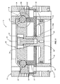
- Tool changer 10 basically comprises a first unit and a second unit that are adapted to be coupled together.
- the first unit is indicated generally by the numeral 12 and is sometimes referred to as a master unit.
- the second unit is indicated generally by the numeral 13 and sometimes referred to as the tool unit.
- the first or master unit 12 is typically connected to a robotic arm (not shown) while the second or tool unit 13 is typically connected to a particular tooL
- the respective tool units 13 are coupled and decoupled to the first and master unit 12.
- the robotic tool changer 10 disclosed herein is similar in many respects to that disclosed in U.S. Patent No. 5,211,501 .
- the robotic tool changer 10 includes additional facilities for the provision of various services and utilities to the attached tool.
- a master electrical contact with the master unit 12. This permits electrical service to be channeled through the master unit 12, through the tool unit 13 and ultimately to the tool.
- relatively large electrical currents such as those utilized by a welding tool can be passed from an electrical source through the robotic system to the tool unit 13.
- fluids such as pneumatics can be transferred through the master unit 12 to the tool unit 13 for use by a particular tool connected thereto.
- robotic tool changers include hydraulic fluid, cooping fluid, oil, and data transfer. Details of these services and utilities are not dealt with here in detail because such is not per se material to the present invention and because robotic tool changers of the general type shown herein are commercially known and available.
- the fluid chamber 14 is cylindrical and includes a cylindrical wall 16. Adjacent to the fluid chamber 14 is a structure that includes a horizontal member 18 that includes an annular ring 20 projecting therefrom. Horizontal member 18 forms one end of the fluid chamber 14. Additionally, horizontal member 18 includes a central opening 18A having an O-ring 18B secured in an annular groove formed in the central opening. Formed in the annular ring 20 is a series of apertures or openings 22. A rolling member 24 is generally held or disposed in each of the apertures or openings 22. The area in and around the apertures 22 is sometimes referred to as a retention area because this area tends to at least partially retain the rolling members 24 that, as will be discussed subsequently herein, are utilized to lock the master unit 12 with the tool unit 13.
- Piston 30 is actuated back and forth in the fluid chamber 14 by a pressurized fluid source. In one embodiment, the piston 30 is pneumatically moved back and forth. Piston 30 includes a longitudinal axis indicated by the numeral 32. Further, piston 30 includes a base 34 that is slidably contained within the fluid chamber 14 and forms a fluid tight seal with the chamber to prevent air or other fluid from bypassing the base. More particularly, the base 34 is provided with an O-ring 36 that seals against the cylindrical wall 16 of the fluid chamber 14. Centered with respect to the base 34 is a stem 38. Preferably the longitudinal axis 32 extends centrally through the stem 38.
- stem 38 extends through the opening 18A formed in the horizontal member 18.
- a generally cylindrical head indicated generally by the numeral 40 Secured to the stem is a generally cylindrical head indicated generally by the numeral 40.
- a screw 42 extends through a portion of the head 40 and into a threaded cavity formed in the stem 18. By tightening the screw 42 the head 40 of the piston 30 is coupled or connected to the base 34 of the piston.
- the outer perimeter of the head 40 is configured to engage the rolling members 24 to effectuate locking the master unit 12 to the tool unit 13.
- the outer perimeter of the head is particularly configured to cooperate with the locking members 24 to achieve both a locking and an unlocking function.
- the outer perimeter or outer area of the head 40 includes a contact area for contacting the rolling members 24 and for urging the rolling members 24 into a locked relationship with a portion of the tool unit 13 to be described subsequently herein.
- Locking surface 50 is disposed at a taper or an angle with respect to the longitudinal axis 32. Note as viewed in Figures 7A and 7B , the locking surface 50 tapers generally upwardly and inwardly with respect to the longitudinal axis 32. As will be discussed subsequently herein, when the piston 30 assumes the locked position, locking surface 50 will engage the respective rolling members 24 and cause the rolling members 24 to engage a portion of the tool unit 13 and lock the master unit 12 and the tool unit 13 together.
- a contact surface 56 that is sometimes referred to as an unlocking surface.
- the contact surface 56 is tapered upwardly and inwardly towards the longitudinal axis 32.
- Contact surface 56 provides two functions. As the piston 30 moves from the unlocked position to the locked position, the contact surface 56 surrounding the head 40 of the piston will contact the rolling members 24 and urge the same outwardly through the openings or apertures 22 formed in the annular ring 20. Thus, surface 56 can be referred to as a contact surface. In addition, when the piston 30 assumes the unlocked position, the contact surface 56 will lie adjacent the rolling members 24 as shown in Figure 6 .
- the rolling members 24 are permitted to move to one side of the apertures 22 as shown in Figure 6 .
- the contact surface 56 of the piston 30 will prevent the rolling members 24 from falling from the apertures 22.
- the position of the rolling members 24 will permit the tool unit 13 to be decoupled from the master unit 12 without interference from the rolling members 24.
- the surface 56 is sometimes referred to as an unlocking surface.
- a failsafe surface 52 Disposed adjacent the locking surface 50 is a failsafe surface 52.
- a portion of the failsafe surface 52 includes a generally cylindrical surface that extends generally parallel to the longitudinal axis 32 of the piston 30.
- the failsafe surface 52 also includes another portion which is referred to as a retarding surface 52A.
- the failsafe surface 52 extends generally between the locking surface 50 and the unlocking surface 56.
- the cylindrical portion of the failsafe surface 52 is disposed adjacent the locking surface 50.
- the retarding portion 52A of the locking surface is disposed adjacent the unlocking surface 56.
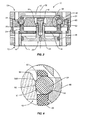
- the purpose of the falisafe surface 52 is to prevent the piston 30 from inadvertently or accidentally moving from the locked position shown in Figure 1 to the unlocked position shown in Figures 5 and 6 .
- the rolling members 24 will cause a force to be directed against the piston head 40 that will tend to drive the piston to the unlocked position in the event of an interruption in the actuating force that urges the piston to the locked position. If there is an inadvertent interruption in the actuating force acting on the piston 30, then the piston will tend to move from the locked position in Figure 1 to the falisafe position shown in Figures 3 and 4 .
- the cylindrical portion of the failsafe surface 52 will, in many cases, aid in maintaining a coupled relationship between the master unit 12 and the tool unit 13. However, the normal force directed against the rolling members 24 by the cylindrical portion of the failsafe surface 52 will produce no significant force component in the axial direction.
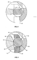
- the retarding surface 52A that forms a part of the failsafe surface 52 projects at least slightly outwardly from the cylindrical portion of the failsafe surface. The engagement of the retarding surface 52A with the rolling members 24 will give rise to at least a slight resistance to further movement of the piston towards the unlocked position.
- the retarding surface 52A assumes the form of a ridge.
- the ridge that forms the retarding surface 52A is disposed generally between the cylindrical portion of the failsafe surface 52 and the contact or unlocking surface 56.
- the dimensions of the ridge may vary, it is contemplated that the ridge may project outwardly approximately 0.254 to 1.016 mm (0.010 to 0.040 inches) past the cylindrical portion of the failsafe surface.
- the relationship of the retarding surface 52A in Figures 7A and 7B Here the ridge forming the retarding surface 52A lies generally between the unlocking surface 56 and the cylindrical portion of the failsafe surface 52.
- the master unit 12 is adapted to be coupled to the tool unit.
- the tool unit 13 is provided with a locking race 60.
- the locking race 60 which forms a part of the tool unit 13, is designed to be inserted into the master unit 12 and to assume a position outwardly of and adjacent the rolling members 24. See Figures 1-6 .
- Locking race 60 includes a locking surface 62.
- the piston 30 is actuated and driven upwardly as viewed in Figure 1 .
- the locking surface 50 of the piston 30 will engage the rolling members 24 urging them outwardly through the apertures 22 of the annular ring 20.
- the rolling members 24 will engage the locking surface 62 that forms a part of the tool unit 14 and will urge the locking race 60 downwardly as viewed in Figure 1 into the locked position shown therein.
- the failsafe surface 52 In the failsafe position shown in Figures 4 and 7A , the failsafe surface 52 still engages the rolling members 24.
- the failsafe surface aids in maintaining the coupled relationship between the master unit 12 and the tool unit 13 even though there is no significant opposing axial force created.
- the piston 30 attempts to move past the ridge or retarding surface 52A there will be an opposing axial force created by the engagement of the ridge with the rolling members 24.
- This will provide at least a slight and positive resistance that must be overcome in order for the piston 30 to move to the unlocked position. That is, as the rolling members attempt to clear the ridge, there will be at least a slight opposing axial force created.
- the locking race 60 is free to move from the coupled position. More particularly, the unlocking surface 56 permits the rolling members 24 to assume the position shown in Figure 6 , which in turn frees the locking race 60, which of course means that the tool unit 13 can be decoupled from the master unit 12.
- a second embodiment is shown for the contact area of the head 40 of the piston 30.
- the failsafe surface 52 comprised a ridge disposed between the locking surface 50 and the contact or unlocking surface 56.
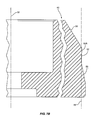
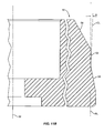
- the failsafe surface 52 forms a generally conical shape surface between the locking surface 50 and the contact or unlocking surface 56. That is, as viewed in Figures 11A and 11B , the failsafe surface 52 extends upwardly and slightly outwardly to a point where the failsafe surface joins the contact or unlocking surface 56. If the failsafe surface 52 is projected downwardly around the piston 30, the projecting lines would form a cone.
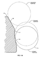
- the angle of the conical surface 52 is slight. As illustrated in Figure 11B , the angle of the conical surface 52 with respect to a reference line RF, which is parallel to the longitudinal axis 32 of the piston, is preferably about 2° but may range from approximately 1° to 5°. Note that the angle of the conical surface 52 is represented by angle A ( Figure 11B ) which is formed by reference line RF and construction line CL which is an extension of the conical or retarding surface 52.
- the piston 30 will tend, as viewed in Figure 9 , to move downwardly to where the rolling members 24 engage the failsafe surface 52. Since the failsafe surface 52 is conical or angled with respect to the longitudinal axis 32 of the piston, the rolling members 24 will be urged at least slightly outwardly as the piston 30 moves from the locked position to the unlocked position. That is, the conical or angled failsafe surface 52 generally prevents the piston from inadvertently moving from the locked position to the unlocked position. This is because the conical shape of the surface 52 forms a retarding surface which effectively retards the movement of the piston downwardly as viewed in Figure 9 without an active unlocking force being applied to the piston.
- FIG. 11C there is a schematic illustration of the opposing axial force that is created or which results when the piston 30 moves from the locked position to the unlocked position.
- a normal force F 1 is created. This force acts perpendicular to conical surface 52 and is directed generally horizontally and slightly upwardly as viewed in Figure 11C .
- Force F 1 includes a horizontal force component F 2 and a vertical or upwardly axial force component F 3 . It is the axial force component F 3 that must be overcome in order for the piston 30 to move from the locked position to the unlocked position.
- Figure 12 illustrates a third embodiment of the contact area of the piston head 40.
- the failsafe surface 52 includes two portions. First there is a generally cylindrical portion 52B and a second conical portion 52A. This design is similar to the embodiment shown in Figures 1-7B with the exception that the conical surface 52B assumes the position of the ridge in the embodiment of Figures 1-7B .
- the rolling members will first engage the cylindrical portion 52B of the failsafe surface, and thereafter will engage the conical or angled surface 52B.
- the conical or angled surface 52B will retard the movement of the piston 30 and prevent the piston 30 from inadvertently or accidentally moving past the conical or angled surface 52B to the unlocked position.
- FIG. 13 a portion of the stem 38 of the piston 30 is shown adjacent the horizontal member 18.
- Stem 38 is provided with a step 38A.
- the dimension of the step can vary. In one embodiment it is contemplated that the step 38A will project outwardly from the stem 38 approximately 0.127 to 0.254 mm (0.005 to 0.010 inches).
- the step 38A will pass through the opening 18A and the horizontal member 18.
- the step 38A will engage the O-ring 18B.
- the engagement of the step 38A with the O-ring 18B will at least slightly retard the further downward movement of the stem 38.
- the engagement of the step 38A with the O-ring 18B will tend to compress or slightly deform the O-ring 18B as the step 38A passes the same.
- Step 38A is strategically placed on the stem 38 in order to protect against the inadvertent or accidental movement of the piston from the failsafe position to the unlocked position.
- the step 38A would lie immediately above the O-ring 18B. If due to vibration or other external forces there was a tendency for the piston 30 to move to the unlocked position, step 38A would engage the O-ring 18B and at least slightly retard the further downward movement of the stem 38. This would effectively hold the piston in the failsafe position.
- the step 38A is relatively small, its presence on a stem 38 would not inhibit or interfere with the normal up and down operation of the stem 38 as it and the piston moves between locked and unlocked positions.
Landscapes
- Engineering & Computer Science (AREA)
- Mechanical Engineering (AREA)
- Robotics (AREA)
- Actuator (AREA)
- Manipulator (AREA)
Claims (14)
- Vollautomatischer Werkzeugwechsler, aufweisend:a. eine erste Einheit (12);b. eine zweite Einheit (13);c. eine Vielzahl von Wälzelementen (24), welche in einem Zurückhaltebereich (22) in einer der Einheiten angeordnet ist;d. einen Kolben (30), welcher in einer der Einheiten des vollautomatischen Werkzeugwechslers beweglich montiert ist und zwischen einer verriegelten und einer entriegelten Position beweglich ist;e. wobei der Kolben in der verriegelten Position funktionsfähig ist, um mit den Wälzelementen in einer der Einheiten in Eingriff zu gelangen und die Wälzelemente gegen eine Fläche der anderen Einheit zu drängen, um die beiden Einheiten miteinander zu verriegeln;f. wobei der Kolben einen Schaft (38) aufweist, welcher durch eine Öffnung (18A) in dem vollautomatischen Werkzeugwechsler vor und zurück beweglich ist; unddadurch gekennzeichnet, dassg. der Schaft des Kolbens eine Stufe (38A) aufweist, um mit einem Abschnitt der Öffnung in Eingriff zu gelangen, wenn der Kolben sich von der verriegelten Position in die entriegelte Position bewegt, und wobei der Eingriff der Stufe des Kolbens mit einem Abschnitt der Öffnung dazu neigt, die weitere Bewegung des Kolbens in die entriegelte Position zu begrenzen.
- Vollautomatischer Werkzeugwechsler nach Anspruch 1, wobei der Schaft eine äußere Fläche mit einer darin ausgebildeten Stufe aufweist und wobei die Öffnung einen O-Ring (18B) aufweist und wobei die Stufe und der O-Ring in Bezug zueinander derartig beabstandet sind, dass, wenn der Kolben sich von der verriegelten Position in die entriegelte Position bewegt, die Stufe mit dem O-Ring in Eingriff kommen wird.
- Vollautomatischer Werkzeugwechsler nach Anspruch 2, wobei die Stufe und der 0- Ring derartig ausgelegt sind, dass, wenn der Kolben sich von der verriegelten Position in die entriegelte Position bewegt, der Eingriff der Stufe mit dem O-Ring den O-Ring veranlassen wird, zumindest leicht verformt zu werden, und der O-Ring die Bewegung des Kolbens zumindest leicht verzögern wird.
- Vollautomatischer Werkzeugwechsler nach einem der vorhergehenden Ansprüche, wobei der Kolben eine ausfallsichere Position zwischen der verriegelten und entriegelten Position einnehmen kann, und wobei die Stufe und Öffnung dazu ausgelegt sind, der Bewegung des Kolbens zwischen der ausfallsicheren Position und der entriegelten Position einen größeren Widerstand aufzuerlegen als zwischen der verriegelten Position und der ausfallsicheren Position.
- Vollautomatischer Werkzeugwechsler nach einem der vorhergehenden Ansprüche, wobei der Kolben Folgendes aufweist: eine Verriegelungsfläche (50), welche wirksam ist, die Wälzelemente in eine Richtung zu drängen, um die erste und zweite Einheit miteinander zu verriegeln; eine Kontaktfläche (56), welche wirksam ist, um den Wälzelementen zu ermöglichen, sich in eine Richtung zu bewegen, um dem ersten und zweiten Element zu ermöglichen, sich zu trennen; eine ausfallsichere Fläche (52), welche allgemein zwischen der Verriegelungsfläche und der Kontaktfläche angeordnet ist; und eine Verzögerungsfläche (52A), wobei die Verzögerungsfläche (52A) mindestens einen Abschnitt der ausfallsicheren Fläche (52) aufweist, welche ausreichend nach außen vorspringt, so dass, wenn sich der Kolben zwischen der verriegelten und entriegelten Position bewegt, der Eingriff der Verzögerungsfläche mit den Wälzelementen zu einer leichten entgegengesetzten Kraft führt, welche überwunden werden muss, damit sich der Kolben von der verriegelten Position in die entriegelte Position bewegt.
- Vollautomatischer Werkzeugwechsler, aufweisend:a. eine erste Einheit (12);b. eine zweite Einheit (13);c. eine Vielzahl von Wälzelementen (24), welche in einem Zurückhaltebereich (22) in einer der Einheiten angeordnet ist;d. einen Kolben (30), welcher innerhalb einer der Einheiten des vollautomatischen Werkzeugwechslers beweglich montiert ist und zwischen einer verriegelten und einer entriegelten Position beweglich ist;e. wobei der Kolben eine Verriegelungsfläche (50), welche wirksam ist, um die Wälzelemente in eine Richtung zu drängen, um die erste und zweite Einheit miteinander zu verriegeln, und eine Kontaktfläche (56) aufweist, welche wirksam ist, um es den Wälzelementen zu ermöglichen, sich in einer Richtung zu bewegen, um es dem ersten und zweiten Element zu ermöglichen, sich zu trennen; undf. der Kolben weiter eine ausfallsichere Fläche (52) aufweist, welche allgemein zwischen der Verriegelungsfläche und der Kontaktfläche angeordnet ist,dadurch gekennzeichnet, dass:g. der Kolben eine Verzögerungsfläche (52A) aufweist, wobei die Verzögerungsfläche (52A) mindestens einen Abschnitt der ausfallsicheren Fläche (52) aufweist und ausreichend nach außen vorspringt, so dass, wenn sich der Kolben zwischen der verriegelten und entriegelten Position bewegt, der Eingriff der Verzögerungsfläche mit den Wälzelementen zu einer leichten entgegengesetzten Kraft führt, welche überwunden werden muss, damit sich der Kolben von der verriegelten Position in die entriegelte Position bewegt.
- Vollautomatischer Werkzeugwechsler nach Anspruch 5 oder 6, wobei die Verzögerungsfläche eine konische Fläche aufweist.
- Vollautomatischer Werkzeugwechsler nach Anspruch 7, wobei die konische Fläche einen Winkel von ungefähr 1° bis 5° mit einer Bezugslinie einschließt, welche sich allgemein parallel zu einer longitudinalen Achse des Kolbens erstreckt.
- Vollautomatischer Werkzeugwechsler nach Anspruch 5 oder 6, wobei die Verzögerungsfläche eine Kante (52A) aufweist.
- Vollautomatischer Werkzeugwechsler nach Anspruch 5 oder 6, wobei die Verzögerungsfläche eine abgewinkelte Oberfläche aufweist.
- Vollautomatischer Werkzeugwechsler nach einem der Ansprüche 7 bis 10, wobei die ausfallsichere Fläche eine zylindrische Fläche aufweist, wobei die zylindrische Fläche zwischen der Verriegelungsfläche und der Verzögerungsfläche liegt.
- Vollautomatischer Werkzeugwechsler nach Anspruch 11, wobei die Verzögerungsfläche allgemein zwischen der Kontaktfläche und der zylindrischen Fläche liegt.
- Vollautomatischer Werkzeugwechsler nach Anspruch 11, wobei die Verzögerungsfläche allgemein benachbart zur Kontaktfläche liegt und die zylindrische Fläche allgemein benachbart zur Verriegelungsfläche liegt.
- Vollautomatischer Werkzeugwechsler nach einem der Ansprüche 5 bis 13, wobei die Verzögerungsfläche auf dem Kolben derartig orientiert ist, dass, wenn sich der Kolben von der verriegelten Position in die entriegelte Position bewegt, die Wälzelemente zwischen der Verzögerungsfläche und einer mit einer der Einheiten verknüpften Verriegelungsfläche zusammengedrückt werden.
Applications Claiming Priority (2)
| Application Number | Priority Date | Filing Date | Title |
|---|---|---|---|
| US11/374,706 US8005570B2 (en) | 2006-03-14 | 2006-03-14 | Robotic tool changer |
| PCT/US2007/062940 WO2007106662A2 (en) | 2006-03-14 | 2007-02-28 | Robotic tool changer |
Publications (4)
| Publication Number | Publication Date |
|---|---|
| EP1993764A2 EP1993764A2 (de) | 2008-11-26 |
| EP1993764A4 EP1993764A4 (de) | 2009-04-15 |
| EP1993764B1 true EP1993764B1 (de) | 2016-10-26 |
| EP1993764B8 EP1993764B8 (de) | 2017-01-04 |
Family
ID=38510147
Family Applications (1)
| Application Number | Title | Priority Date | Filing Date |
|---|---|---|---|
| EP07778763.8A Active EP1993764B8 (de) | 2006-03-14 | 2007-02-28 | Roboterwerkzeugwechsler |
Country Status (5)
| Country | Link |
|---|---|
| US (1) | US8005570B2 (de) |
| EP (1) | EP1993764B8 (de) |
| JP (1) | JP2009530121A (de) |
| KR (1) | KR20090008192A (de) |
| WO (1) | WO2007106662A2 (de) |
Cited By (2)
| Publication number | Priority date | Publication date | Assignee | Title |
|---|---|---|---|---|
| EP4209316A1 (de) * | 2022-01-07 | 2023-07-12 | SMC Corporation | Endeffektoraustauschvorrichtung |
| TWI914578B (zh) | 2022-01-07 | 2026-02-11 | 日商Smc股份有限公司 | 末端執行器交換裝置 |
Families Citing this family (56)
| Publication number | Priority date | Publication date | Assignee | Title |
|---|---|---|---|---|
| US8132816B2 (en) * | 2006-04-04 | 2012-03-13 | Ati Industrial Automation, Inc. | Electrically Actuated Robotic Tool Changer |
| US8500132B2 (en) * | 2006-04-04 | 2013-08-06 | Ati Industrial Automation, Inc. | Rotating coupling for robotic tool changer with one-way clutch and dual-button handle mechanism |
| US8601667B2 (en) * | 2006-04-04 | 2013-12-10 | Ati Industrial Automation, Inc. | Rotating coupling for robotic tool changer with actuation mechanism |
| US8209840B2 (en) * | 2006-04-04 | 2012-07-03 | Ati Industrial Automation, Inc. | Rotating coupling for robotic tool changer |
| US8152173B2 (en) * | 2006-08-04 | 2012-04-10 | Ingersoll Machine Tools, Inc. | Clamping apparatus and method |
| CN101524845B (zh) * | 2008-03-05 | 2013-01-09 | 鸿富锦精密工业(深圳)有限公司 | 夹持机构 |
| CN101543993B (zh) * | 2008-03-25 | 2012-03-28 | 鸿富锦精密工业(深圳)有限公司 | 机械手 |
| CN101607398B (zh) * | 2008-06-18 | 2012-06-20 | 鸿富锦精密工业(深圳)有限公司 | 夹具更换装置 |
| US8533930B2 (en) * | 2008-09-05 | 2013-09-17 | Ati Industrial Automation, Inc. | Manual robotic tool changer having rapid coupling mechanism |
| US9724830B2 (en) | 2008-09-05 | 2017-08-08 | Ati Industrial Automation, Inc. | Manual robotic tool changer with rolling members |
| FI20100081A0 (fi) | 2010-02-24 | 2010-02-24 | Raumaster Paper Oy | Laitteisto tarttujan vaihtoon sekä rullavarasto |
| USD621859S1 (en) * | 2010-05-14 | 2010-08-17 | Tormach Llc | Tool changer fork |
| ITTV20120129A1 (it) * | 2012-07-11 | 2014-01-12 | Almerino Canuto | Dispositivo di compensazione del disassamento in sistemi di bloccaggio automatici |
| JP5966010B2 (ja) * | 2012-09-21 | 2016-08-10 | ビー・エル・オートテック株式会社 | 工具交換装置 |
| US9151343B2 (en) * | 2013-03-14 | 2015-10-06 | Ati Industrial Automation, Inc. | Ball lock compensator for use with a robotic device |
| JP2014217909A (ja) * | 2013-05-07 | 2014-11-20 | ビー・エル・オートテック株式会社 | 工具交換装置用のマスター装置 |
| CH709351A1 (de) * | 2014-03-11 | 2015-09-15 | Erowa Ag | Kupplungsvorrichtung für ein Handhabungsgerät. |
| GB201411392D0 (en) * | 2014-06-26 | 2014-08-13 | Black & Decker Inc | A tool holder |
| KR101949057B1 (ko) * | 2014-08-20 | 2019-02-15 | 에이티아이 인더스트리얼 오토메이션, 인크. | 공구 스탠드 디커플링 전원을 갖는 로봇식 공구 교환기 |
| US10661449B2 (en) | 2014-08-20 | 2020-05-26 | Ati Industrial Automation, Inc. | Safe robotic tool changer |
| US11097390B2 (en) | 2014-08-20 | 2021-08-24 | Ati Industrial Automation, Inc. | Pneumatic safety interlock |
| JP6475979B2 (ja) * | 2014-12-26 | 2019-02-27 | ニッタ株式会社 | 係合部品、雌型部材、及び工具交換装置 |
| US9677582B2 (en) * | 2015-01-09 | 2017-06-13 | Northrop Grumman Systems Corporation | Fluid-actuated fastening device |
| US10105855B2 (en) | 2015-02-16 | 2018-10-23 | Norgren Automation Solutions, Llc | Quick disconnect apparatus for modular tooling |
| US9981391B2 (en) | 2015-02-16 | 2018-05-29 | Norgren Automation Solutions, Llc | Quick disconnect apparatus for modular tooling |
| EP4205689B1 (de) | 2015-02-20 | 2025-04-02 | Stryker Corporation | Sterile sperranordnung zur kopplung chirurgischer komponenten dadurch |
| TWI593525B (zh) * | 2015-06-02 | 2017-08-01 | Hiwin Tech Corp | Mechanical replacement device and method for exchanging end effectors |
| JP6030718B1 (ja) | 2015-07-03 | 2016-11-24 | 上銀科技股▲分▼有限公司 | 末端効果器を交換する機械式交換装置 |
| US10286566B2 (en) * | 2015-10-06 | 2019-05-14 | Oceaneering International, Inc. | Manipulator end effector |
| DE102016222287A1 (de) | 2015-11-12 | 2017-05-18 | Ati Industrial Automation, Inc. | Sicherer roboterwerkzeugwechsler |
| ITUB20155846A1 (it) | 2015-11-24 | 2017-05-24 | Gimatic S R L | Dispositivo cambia utensile |
| JP6321852B1 (ja) * | 2017-04-06 | 2018-05-09 | エスアールエンジニアリング株式会社 | ロボットアームのカップリング装置 |
| US10335957B2 (en) * | 2017-04-25 | 2019-07-02 | Ati Industrial Automation, Inc. | Magnetically activated tool changer |
| USD898879S1 (en) | 2017-05-01 | 2020-10-13 | Norgren Automation Solutions, Llc | Modular tooling coupler |
| CN107081781A (zh) * | 2017-06-28 | 2017-08-22 | 深圳市恒拓高工业技术股份有限公司 | 一种工业机器人末端工具的快速更换装置及其更换方法 |
| WO2019114893A1 (en) * | 2017-12-14 | 2019-06-20 | Onrobot A/S | Gripping device |
| US10773817B1 (en) | 2018-03-08 | 2020-09-15 | Northrop Grumman Systems Corporation | Bi-directional flow ram air system for an aircraft |
| US11806096B2 (en) | 2018-12-04 | 2023-11-07 | Mako Surgical Corp. | Mounting system with sterile barrier assembly for use in coupling surgical components |
| CN219027426U (zh) * | 2020-03-23 | 2023-05-16 | 米沃奇电动工具公司 | 旋转锤 |
| US20210370531A1 (en) | 2020-05-28 | 2021-12-02 | Ati Industrial Automation, Inc. | Pin, Toroidal Spring Socket, and High-Current Connector for a Robotic Device |
| US11850733B2 (en) * | 2020-06-11 | 2023-12-26 | Ati Industrial Automation, Inc. | Robotic tool changer coupling mechanism with increased torsional rigidity and reduced freeplay |
| JP7159506B2 (ja) * | 2020-07-01 | 2022-10-24 | ビー・エル・オートテック株式会社 | ツール交換装置 |
| US12090638B2 (en) | 2020-08-25 | 2024-09-17 | Ati Industrial Automation, Inc. | Robotic tool changer having debris passages for channeling debris from the ball-locking mechanism |
| US11691294B2 (en) * | 2020-09-22 | 2023-07-04 | Ati Industrial Automation, Inc. | Robotic tool changer coupling mechanism with increased torsional stiffness |
| RU2743389C1 (ru) * | 2020-10-22 | 2021-02-17 | Федеральное государственное автономное образовательное учреждение высшего образования «Дальневосточный федеральный университет» (ДВФУ) | Узел автоматического крепления съемного элемента |
| JP7608959B2 (ja) * | 2021-04-22 | 2025-01-07 | Smc株式会社 | エンドエフェクタ交換装置 |
| FR3122594B1 (fr) | 2021-05-04 | 2023-05-26 | Commissariat Energie Atomique | Interface porte-outil de bras robotisé à décalage angulaire |
| US11931663B2 (en) | 2021-07-30 | 2024-03-19 | Tait Towers Manufacturing, LLC | Active damping system for suspended ride system |
| US11806634B2 (en) | 2021-07-30 | 2023-11-07 | Tait Towers Manufacturing, LLC | Connection system for suspended loads for ride systems |
| US11856898B2 (en) | 2021-08-03 | 2024-01-02 | 4Ag Robotics Inc. | Automated mushroom harvesting system |
| US11963733B2 (en) | 2021-12-01 | 2024-04-23 | Nuvasive Inc. | Connector assemblies for connecting a robotic arm with a medical end effector |
| US20230240793A1 (en) * | 2022-02-02 | 2023-08-03 | Mako Surgical Corp. | Quick-Connect Mounting System For Surgical Components |
| US20240342927A1 (en) | 2023-04-17 | 2024-10-17 | Ati Industrial Automation, Inc. | Manual Robotic Tool Changer with Generally Opposed Decoupling Actuation Force and Safety Latch Actuation Force |
| WO2025091105A1 (en) | 2023-10-30 | 2025-05-08 | 4Ag Robotics Inc. | Machine-learning virtualization-enabled harvesting |
| WO2025166444A1 (en) | 2024-02-08 | 2025-08-14 | 4Ag Robotics Inc. | Machine-learning-enabled tool changer for mushroom crop management system |
| US12377567B1 (en) | 2024-11-22 | 2025-08-05 | 4Ag Robotics Inc. | Mushroom trimming and sorting system |
Family Cites Families (19)
| Publication number | Priority date | Publication date | Assignee | Title |
|---|---|---|---|---|
| DE3069513D1 (en) * | 1979-10-22 | 1984-11-29 | Toyoda Machine Works Ltd | Tool storage magazine for machine tool |
| FR2542243B1 (fr) * | 1983-03-11 | 1987-01-23 | Syspro | Porte-outil pour robot industriel |
| DE3347423A1 (de) * | 1983-12-29 | 1985-07-11 | Rudi 4018 Langenfeld Kirst | Vorrichtung zum automatischen auswechseln und kuppeln von greifern an robotern oder handhabungsgeraeten |
| US4679956A (en) * | 1986-01-08 | 1987-07-14 | General Motors Corporation | Quick disconnect device |
| US4696524A (en) * | 1986-03-03 | 1987-09-29 | Custom Tool & Mfg. Co. | Robot arm coupling apparatus |
| DE3710472A1 (de) * | 1987-03-30 | 1988-10-20 | Erowa Ag | Vorrichtung zur loesbaren befestigung von werkzeugen an einem handhabungsgeraet |
| US4906123A (en) * | 1988-03-02 | 1990-03-06 | Wes-Tech, Inc. | Quick changecoupling system for robotic attachments |
| US4886467A (en) * | 1989-06-02 | 1989-12-12 | Chrysler Motors Corporation | Quick change tool holder |
| US5002500A (en) * | 1990-03-02 | 1991-03-26 | General Motors Corporation | Quick connect/disconnector for high amperage current |
| JP2505624B2 (ja) * | 1990-06-28 | 1996-06-12 | ビー・エル・オートテック株式会社 | ロボットア―ムカップリング装置用マスタプレ―ト及びツ―ルプレ―ト並びにそれらを組み合わせたロボットア―ムカップリング装置 |
| DE9303050U1 (de) * | 1993-03-03 | 1993-04-22 | Festo AG & Co, 73734 Esslingen | Fluidisch betätigbarer Arbeitszylinder |
| DE29615613U1 (de) * | 1996-09-09 | 1997-08-28 | Stark, Emil, Götzis | Spannvorrichtung zum Spannen eines Schnellspannzylinders auf einer Trägerplatte für Bearbeitungsmaschinen |
| DE29718726U1 (de) * | 1997-10-10 | 1999-02-18 | KUKA Schweissanlagen GmbH, 86165 Augsburg | Wechselkupplung |
| WO2000027596A1 (en) * | 1998-11-05 | 2000-05-18 | Pascal Kabushiki Kaisha | Tool connecting device for robot hand |
| EP1308249A4 (de) * | 2000-07-06 | 2005-04-06 | Pascal Eng Corp | Vorrichtung zur verbindung eines werkzeuges an einer roboterhand |
| FR2817596B1 (fr) * | 2000-12-06 | 2003-09-19 | Faurecia Sieges Automobile | Systeme d'assemblage au moyen d'un dispositif d'ancrage a billes |
| US7252453B1 (en) | 2002-05-29 | 2007-08-07 | Ati Industrial Automation, Inc. | Robot arm coupling apparatus |
| US7374524B2 (en) * | 2004-08-17 | 2008-05-20 | Delaware Capital Formation, Inc. | Method, system and program product for enabling rapid connection of automated tools to a device network |
| US8132816B2 (en) * | 2006-04-04 | 2012-03-13 | Ati Industrial Automation, Inc. | Electrically Actuated Robotic Tool Changer |
-
2006
- 2006-03-14 US US11/374,706 patent/US8005570B2/en active Active
-
2007
- 2007-02-28 JP JP2009500545A patent/JP2009530121A/ja active Pending
- 2007-02-28 WO PCT/US2007/062940 patent/WO2007106662A2/en not_active Ceased
- 2007-02-28 EP EP07778763.8A patent/EP1993764B8/de active Active
- 2007-02-28 KR KR1020087023392A patent/KR20090008192A/ko not_active Ceased
Cited By (2)
| Publication number | Priority date | Publication date | Assignee | Title |
|---|---|---|---|---|
| EP4209316A1 (de) * | 2022-01-07 | 2023-07-12 | SMC Corporation | Endeffektoraustauschvorrichtung |
| TWI914578B (zh) | 2022-01-07 | 2026-02-11 | 日商Smc股份有限公司 | 末端執行器交換裝置 |
Also Published As
| Publication number | Publication date |
|---|---|
| US20070235949A1 (en) | 2007-10-11 |
| WO2007106662A3 (en) | 2008-05-02 |
| JP2009530121A (ja) | 2009-08-27 |
| EP1993764B8 (de) | 2017-01-04 |
| WO2007106662A2 (en) | 2007-09-20 |
| EP1993764A2 (de) | 2008-11-26 |
| KR20090008192A (ko) | 2009-01-21 |
| US8005570B2 (en) | 2011-08-23 |
| EP1993764A4 (de) | 2009-04-15 |
Similar Documents
| Publication | Publication Date | Title |
|---|---|---|
| EP1993764B1 (de) | Roboterwerkzeugwechsler | |
| US10335957B2 (en) | Magnetically activated tool changer | |
| US8209840B2 (en) | Rotating coupling for robotic tool changer | |
| US8727329B2 (en) | Mounting system | |
| US8726923B2 (en) | Safety valve | |
| US6196523B1 (en) | Stop valve | |
| JP5674010B2 (ja) | クランプ装置 | |
| EP1338374B2 (de) | Vorrichtung zur automatischen Positionierung eines beweglichen Teiles auf einen Referenzteil | |
| US20070158891A1 (en) | Quick action clamping cylinder with a simplified structure | |
| US20100219574A1 (en) | Quick action clamping cylinder with a simplified structure | |
| TWI756873B (zh) | 夾持裝置 | |
| CN219925208U (zh) | 夹紧装置 | |
| WO2011087851A2 (en) | Toolholder assembly | |
| TW201516273A (zh) | 流體壓缸 | |
| JP5027133B2 (ja) | 工具用又はワーク用の位置決め・クランプ装置 | |
| EP2831434B1 (de) | Einen Träger enthaltendes Kugellager | |
| JP2001087965A (ja) | 工作機械とそれに結合された工作物キャリアとの間の電気的接続を含む、様々な媒体用の機械上に位置する供給ラインを接続する結合システム | |
| US20210095715A1 (en) | Joint assembly for motion simulator | |
| JP4900714B2 (ja) | 可溶栓 | |
| US20110030805A1 (en) | Blowout preventer with lock | |
| US8042575B2 (en) | Spring energized plug | |
| US5687962A (en) | Bearing locking mechanism, work support | |
| JP2009136941A (ja) | ロボットアームカップリング装置の脱落防止装置 | |
| US11572903B2 (en) | Pneumatic cylinder device with holding valve | |
| US20080190282A1 (en) | Lockable Working Cylinder |
Legal Events
| Date | Code | Title | Description |
|---|---|---|---|
| PUAI | Public reference made under article 153(3) epc to a published international application that has entered the european phase |
Free format text: ORIGINAL CODE: 0009012 |
|
| 17P | Request for examination filed |
Effective date: 20080930 |
|
| AK | Designated contracting states |
Kind code of ref document: A2 Designated state(s): AT BE BG CH CY CZ DE DK EE ES FI FR GB GR HU IE IS IT LI LT LU LV MC NL PL PT RO SE SI SK TR |
|
| AX | Request for extension of the european patent |
Extension state: AL BA HR MK RS |
|
| RIC1 | Information provided on ipc code assigned before grant |
Ipc: G06F 19/00 20060101AFI20081103BHEP |
|
| A4 | Supplementary search report drawn up and despatched |
Effective date: 20090317 |
|
| RIC1 | Information provided on ipc code assigned before grant |
Ipc: B25J 15/04 20060101AFI20090311BHEP |
|
| DAX | Request for extension of the european patent (deleted) | ||
| RBV | Designated contracting states (corrected) |
Designated state(s): DE FR GB IT SE |
|
| 17Q | First examination report despatched |
Effective date: 20090619 |
|
| REG | Reference to a national code |
Ref country code: DE Ref legal event code: R079 Ref document number: 602007048475 Country of ref document: DE Free format text: PREVIOUS MAIN CLASS: B23B0031400000 Ipc: B25J0015040000 |
|
| GRAP | Despatch of communication of intention to grant a patent |
Free format text: ORIGINAL CODE: EPIDOSNIGR1 |
|
| RIC1 | Information provided on ipc code assigned before grant |
Ipc: B23B 31/30 20060101ALI20160519BHEP Ipc: B25J 15/04 20060101AFI20160519BHEP Ipc: B23B 31/107 20060101ALI20160519BHEP |
|
| INTG | Intention to grant announced |
Effective date: 20160608 |
|
| GRAS | Grant fee paid |
Free format text: ORIGINAL CODE: EPIDOSNIGR3 |
|
| GRAA | (expected) grant |
Free format text: ORIGINAL CODE: 0009210 |
|
| AK | Designated contracting states |
Kind code of ref document: B1 Designated state(s): DE FR GB IT SE |
|
| REG | Reference to a national code |
Ref country code: GB Ref legal event code: FG4D |
|
| GRAT | Correction requested after decision to grant or after decision to maintain patent in amended form |
Free format text: ORIGINAL CODE: EPIDOSNCDEC |
|
| REG | Reference to a national code |
Ref country code: DE Ref legal event code: R096 Ref document number: 602007048475 Country of ref document: DE |
|
| RAP2 | Party data changed (patent owner data changed or rights of a patent transferred) |
Owner name: ATI INDUSTRIAL AUTOMATION, INC. |
|
| PG25 | Lapsed in a contracting state [announced via postgrant information from national office to epo] |
Ref country code: SE Free format text: LAPSE BECAUSE OF FAILURE TO SUBMIT A TRANSLATION OF THE DESCRIPTION OR TO PAY THE FEE WITHIN THE PRESCRIBED TIME-LIMIT Effective date: 20161026 |
|
| REG | Reference to a national code |
Ref country code: DE Ref legal event code: R026 Ref document number: 602007048475 Country of ref document: DE |
|
| PLBI | Opposition filed |
Free format text: ORIGINAL CODE: 0009260 |
|
| 26 | Opposition filed |
Opponent name: ROBOTOOLS S.R.L. Effective date: 20170725 |
|
| PLAX | Notice of opposition and request to file observation + time limit sent |
Free format text: ORIGINAL CODE: EPIDOSNOBS2 |
|
| GBPC | Gb: european patent ceased through non-payment of renewal fee |
Effective date: 20170228 |
|
| REG | Reference to a national code |
Ref country code: FR Ref legal event code: ST Effective date: 20171031 |
|
| PLAF | Information modified related to communication of a notice of opposition and request to file observations + time limit |
Free format text: ORIGINAL CODE: EPIDOSCOBS2 |
|
| PG25 | Lapsed in a contracting state [announced via postgrant information from national office to epo] |
Ref country code: FR Free format text: LAPSE BECAUSE OF NON-PAYMENT OF DUE FEES Effective date: 20170228 |
|
| PG25 | Lapsed in a contracting state [announced via postgrant information from national office to epo] |
Ref country code: IT Free format text: LAPSE BECAUSE OF NON-PAYMENT OF DUE FEES Effective date: 20170228 Ref country code: GB Free format text: LAPSE BECAUSE OF NON-PAYMENT OF DUE FEES Effective date: 20170228 |
|
| PLBB | Reply of patent proprietor to notice(s) of opposition received |
Free format text: ORIGINAL CODE: EPIDOSNOBS3 |
|
| PLBP | Opposition withdrawn |
Free format text: ORIGINAL CODE: 0009264 |
|
| PLAU | Termination of opposition procedure: information related to despatch of decision deleted |
Free format text: ORIGINAL CODE: EPIDOSDOPC1 |
|
| PLBD | Termination of opposition procedure: decision despatched |
Free format text: ORIGINAL CODE: EPIDOSNOPC1 |
|
| PLBD | Termination of opposition procedure: decision despatched |
Free format text: ORIGINAL CODE: EPIDOSNOPC1 |
|
| REG | Reference to a national code |
Ref country code: DE Ref legal event code: R100 Ref document number: 602007048475 Country of ref document: DE |
|
| PLBM | Termination of opposition procedure: date of legal effect published |
Free format text: ORIGINAL CODE: 0009276 |
|
| STAA | Information on the status of an ep patent application or granted ep patent |
Free format text: STATUS: OPPOSITION PROCEDURE CLOSED |
|
| 27C | Opposition proceedings terminated |
Effective date: 20190126 |
|
| PGFP | Annual fee paid to national office [announced via postgrant information from national office to epo] |
Ref country code: DE Payment date: 20260224 Year of fee payment: 20 |