EP1993787B1 - Porte-outil à serrage rapide destiné à des inserts de tournevis - Google Patents
Porte-outil à serrage rapide destiné à des inserts de tournevis Download PDFInfo
- Publication number
- EP1993787B1 EP1993787B1 EP07701907A EP07701907A EP1993787B1 EP 1993787 B1 EP1993787 B1 EP 1993787B1 EP 07701907 A EP07701907 A EP 07701907A EP 07701907 A EP07701907 A EP 07701907A EP 1993787 B1 EP1993787 B1 EP 1993787B1
- Authority
- EP
- European Patent Office
- Prior art keywords
- bit
- quick
- magnet
- locking
- change holder
- Prior art date
- Legal status (The legal status is an assumption and is not a legal conclusion. Google has not performed a legal analysis and makes no representation as to the accuracy of the status listed.)
- Not-in-force
Links
Images





Classifications
-
- B—PERFORMING OPERATIONS; TRANSPORTING
- B25—HAND TOOLS; PORTABLE POWER-DRIVEN TOOLS; MANIPULATORS
- B25B—TOOLS OR BENCH DEVICES NOT OTHERWISE PROVIDED FOR, FOR FASTENING, CONNECTING, DISENGAGING, OR HOLDING
- B25B23/00—Details of, or accessories for, spanners, wrenches, screwdrivers
- B25B23/0007—Connections or joints between tool parts
- B25B23/0035—Connection means between socket or screwdriver bit and tool
-
- B—PERFORMING OPERATIONS; TRANSPORTING
- B23—MACHINE TOOLS; METAL-WORKING NOT OTHERWISE PROVIDED FOR
- B23B—TURNING; BORING
- B23B31/00—Chucks; Expansion mandrels; Adaptations thereof for remote control
- B23B31/02—Chucks
- B23B31/10—Chucks characterised by the retaining or gripping devices or their immediate operating means
- B23B31/107—Retention by laterally-acting detents, e.g. pins, screws, wedges; Retention by loose elements, e.g. balls
- B23B31/1071—Retention by balls
-
- B—PERFORMING OPERATIONS; TRANSPORTING
- B25—HAND TOOLS; PORTABLE POWER-DRIVEN TOOLS; MANIPULATORS
- B25B—TOOLS OR BENCH DEVICES NOT OTHERWISE PROVIDED FOR, FOR FASTENING, CONNECTING, DISENGAGING, OR HOLDING
- B25B15/00—Screwdrivers
- B25B15/001—Screwdrivers characterised by material or shape of the tool bit
-
- B—PERFORMING OPERATIONS; TRANSPORTING
- B25—HAND TOOLS; PORTABLE POWER-DRIVEN TOOLS; MANIPULATORS
- B25B—TOOLS OR BENCH DEVICES NOT OTHERWISE PROVIDED FOR, FOR FASTENING, CONNECTING, DISENGAGING, OR HOLDING
- B25B23/00—Details of, or accessories for, spanners, wrenches, screwdrivers
- B25B23/02—Arrangements for handling screws or nuts
- B25B23/08—Arrangements for handling screws or nuts for holding or positioning screw or nut prior to or during its rotation
- B25B23/12—Arrangements for handling screws or nuts for holding or positioning screw or nut prior to or during its rotation using magnetic means
Definitions
- the present invention relates to a quick-change holder for screwdriver bits according to the preamble of claim 1, which is known from the document US 2001/043841 A is known.
- Screwdriver bits also known as screwdriver bits or simply bits, are known in the art. Such bits are widely used by commercial and private users as interchangeable tips of electrically powered drill and screwdrivers. In recent years, cordless drills and screwdrivers have become popular in the commercial field, as well as in home improvement, so that drilling and screwing with the help of screwdriver bits can be carried out independently of the network in all locations. When working on scaffolding, ladders or in hard-to-reach places, it is of particular importance that the bits can be easily replaced, preferably with one hand, and that a single screwdriver, or a single quick-change bracket with as many different types of bits can be used.
- the screwdriver bits or bits are torque-fitted into a holder, which is formed either on the work spindle of the screwing or in a holder part, which is inserted into a chuck of the screwing.
- the torque-locking driving connection between the holder and the screwdriver bit is usually effected by a hexagon socket receiving the holder and a corresponding hexagon of the screwdriver bit. From the company Fein But also inserts with a participatedflachkant are known, which also ensure a torque-locking driving connection in a corresponding receptacle.
- the external hexagon has a recess of shallow depth, which only penetrates into the edges of the external hexagon.
- the screwdriver bit is held in the receptacle by a spring ring mounted in the hexagon socket of the receptacle, which engages with inserted screwdriver bit into the groove.
- the hexagon socket of the screwdriver bit has a deep groove with a large profile radius.
- a detent ball engages radially into this groove.
- the detent ball is held by an axially spring-loaded sleeve with inner cone in the groove. By moving the sleeve against the spring load of the inner cone releases the detent ball, so that the screwdriver bit can be removed.
- the DE-U-20201021 proposes, therefore, to provide a holder for screwdriver bits, which can accommodate both screwdriver bits Form C and screwdriver bits Form E according to DIN 3126.
- a locking element in the form of a ball is mounted in the hexagon socket of the drive-side recording of the holder, which is formed according to the axial position and the radial depth of the recess of the hexagon of a screwdriver bit of form C according to DIN 3126.
- another ball of elastomeric material is pressed, which axially resiliently supports the screwdriver bit used in the recording.
- the elastomeric elements are designed so that their axial bias supports the removal of a bit, so it can easily lead to that by the additional pressure of the Elastomerelements the bit jumps out of the receiving opening very quickly and the user must catch him sent.
- less skilled users easily lose screwdriver bits from inaccessible areas of the workplace. In this way, a lot of time and labor can be wasted in searching and retrieving.
- a protruding screwdriver bit due to its hardness and weight not insignificant risk of injury.
- another disadvantage is that the elastomeric elements have only a limited life.
- German utility model DE 20303079 The problem of the uncontrolled jumping out of the bits was recognized and it was also recognized that a protruding screwdriver bit due to its hardness and its weight represents a significant risk of injury on construction sites. It is therefore in the DE 20303079 a chuck for tool inserts, in particular a chuck for screwdriver bits proposed, in which two permanent magnets are arranged in the sleeve body. The poles of the same direction face each other, so that the two permanent magnets repel each other. The replacement of the springs by repelling magnets to reduce the risk that the bits when removing too quickly jump out of the chuck.
- the US 2001/0043841 shows a bit holder with a holding mechanism for holding a bit and an ejection means for facilitating the bit replacement, the ejection means having a shuttle which is acted upon by a compression spring and partially releases the bit upon release of a ball lock from the holding mechanism.
- the holding mechanism comprises a spherical Locking element which is pressed by an elastic O-ring in the circumferential groove of the type E bits used.
- a major disadvantage of in the US 2001/0043841 proposed bit holder is that this tends to jamming by the application of force to the ejection means and the holding mechanism, especially with frequent bit change.
- the holding mechanism is designed so that preferably only bits of type E can be held.
- An essential idea of the invention is to provide in the bit holder means for locking the first opening side mounted magnet in a rear holding position, which allow the bit to be inserted with one hand, without a simultaneous manual operation of an outer sleeve is necessary.
- the locking of the magnet in the holding position brings significant benefits.
- the latching element for the bit is greatly relieved, since the axial force of the ejection mechanism is no longer loaded on the bit or the latching element and the bit is also held by the magnet to the other can use bits of different standards, since at a selected axial position of the locking element, the sliding movable mounting of the first magnet allows the insertion of erbits different shapes and standards and these each magnetkraftbeetzschlagt supported in the axial direction.
- bits of various shapes in the inventive quick-change holder can be safely held without disturbing axial play.
- FIG. 1 is a longitudinal section through a quick-change holder 1 for bits shown, which is fixedly mounted on a shaft S of an electrically operated screwdriver or a drill not shown from the machine housing, only a front cover F is shown having a breakthrough D for receiving a on the shaft S. fastened drive-side end 21 of the bit holder 2 has.
- the quick change holder according to the invention instead of on the shaft S of a machine on a hexagon or a flat edge for releasable support in a suitable chuck a drill or a screwdriver can be secured against rotation.
- quick-change holders 1 are understood to mean both those for a fixed machine assembly and those in the form of a change-over holder. It will be apparent to those skilled in the art that how and how the novel teachings of the present invention can be applied to both types without limitation.
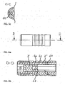
- the bit holder 2 is in the FIGS. 2a to 2f shown in detail. It consists essentially of a hollow cylinder having a cylindrical bore 22 for attachment to a driven shaft S of a drill at a rear drive end.
- the front portion of the bit holder is provided with a hexagon socket 23 for torque-locking recording of the bits. Hexagon socket 23 and cylindrical bore 22 overlap in a central region 24 of the bit holder 2.
- the diameter of the bore 22 is matched to the size of the hexagon socket, that at the front end face of the overlap region six rearwardly directed abutment surfaces 25 are formed.
- In the overlap region passes through a radial bore 26 for receiving the locking element 6, which is preferably designed as a ball, the wall of the bit holder 2.
- In the front region of the hexagon socket is a Tangentialnut 27 cut so deep into the wall that a window 27 'for receiving a Locking element 9 is broken in the hexagon socket 23.
- a first permanent magnet 3 also called ejection magnet
- the first magnet 3 is pressed into a cylindrical seat 31, molded or cast, which is provided on an outer side with a locking groove 32.
- the seat is preferably made of stainless steel or plastic, so that the operations for attaching the groove 32 are easily performed can, the life is high and the magnetic effect is not significantly attenuated.
- the locking groove 32 advantageously extends approximately parallel to the longitudinal axis of the magnet 3 and is adapted in the illustrated embodiment to a spherical locking element 6.
- the groove 32 has a constant radius R, which substantially corresponds to the radius of the locking ball 6, wherein the depth of the groove 32 from the front end 34 to the rear end 35 decreases steadily.
- the pitch ⁇ at the apex of the groove is, according to a preferred embodiment, 7 °.
- the function of the locking groove 32 illustrates the cross section of FIG. 1 , A spherical locking element 6 is inserted into the radial bore 26 in the wall of the bit holder 2.
- An ejector sleeve 5 is mounted coaxially on the bit holder 2, and limits axially displaceable.
- the substantially circular cylindrical ejector sleeve 5 is in the FIG. 3 shown in more detail. On the outside, it is provided in a central region with three circumferential webs 51, which facilitate the gripping and axial displacement of the sleeve 5.
- the webs 51 may also be replaced by a knurled area or a grippy elastomer insert. More important for the function is the design of the inner wall of the sleeve 5.
- the inner diameter of the sleeve 52 widens via a conical section 53 to a circumferential receiving space 54 for a latching or clamping element 9, the function of which will be described in more detail below.
- the rear end of the receiving space 54 is formed by a step at which the inner diameter is reduced again, so that the sleeve 52 in turn sits with little play on the receptacle 2.
- This rear portion 55 extends to the drive-side end of the sleeve and is interrupted only by a circumferential recess 56 which has approximately the same radius as the locking ball 6.
- the rear end of the sleeve forms an inwardly directed rib 57, which in the assembled state, as in the FIG. 1 is shown, a spring 8 serves as an abutment.
- the spring 8 pushes the ejector sleeve 5 to the rear until the locking ball 6 can engage with its radially outward directed portion into the recess 56. On the inward side, the ball engages in the locking groove 32 a.
- the front magnet 3 has a pole of the same direction to the rear magnet 4, so that repel the two permanent magnets. Since the rear magnet 4 rests in a receptacle 41 axially immovable directly on the shaft S, the front magnet 3 is pressed in the direction of the receiving opening 28.
- the locking ball 6 is pressed by the forward movement of the magnet 3 and the decreasing depth of the locking groove 52 outwardly into the recess 56 of the sleeve 5, the diameter of the locking ball 6 is so on the diameter of the cylindrical seat 31 of the ejection magnet 3, the wall thickness of the recording 2 adapted in the transition region and the inner diameter of the sleeve in the puncture area that in the receptive delivery, as shown in the FIG. 1 is shown, the ejection magnet 3 and the sleeve 5 are held in a forward position. In this position, the front end side of the magnet 3 and the magnetic seat 31 abuts against the stop surfaces 25. At the same time, the receiving space 54 of the sleeve 5 is located above the tangential groove 27, so that the latching element 9 essentially releases the window 27 '.
- the spring 8 pushes the sleeve 5 backwards and the ball 6 is locked in the radially inner position.
- the magnet 3 is thereby held in a rear position and can not be moved forward despite the rejection by the second magnet 4.
- the inner cone 53 simultaneously pushes the locking element 9 inwards, so that a part of the locking element protrudes through the window 27 'in the hexagon socket and engages there into the respective recess of the hexagon of the inserted bit.
- the bit is not acted upon in the inserted state with the effective force during ejection
- the axially acting repulsive magnetic force is received with the bit inserted by the locking element 6, so that the Rastemaniente 9 with much play in the recess of Hexagon of the bits can engage and are not loaded.
- the bits are usually made of metallic materials and alloys, which are additionally held by the attraction of the magnet 3 in the receptacle 2, can be dispensed with entirely advantageous locking embodiments 9 in advantageous embodiments. Falling out of the bits used from the bit holder 2 is prevented solely by the attraction of the first magnet 3.
- the adaptation of the axial position of the locking means 9 on the standardized punctures in the bit does not play a significant role and the inventive bit holder can be advantageously with a variety Use bit types of different standards.
- a spacer ring 60 is mounted between the front magnet 3 'and the inserted bit B in the interior of the bit holder 2'.
- the spacer ring 60 with its free central region 61 makes it possible to insert so-called double bits, since in each case the unused working tip is partially inserted into the free space 61 can protrude.
- the spacer ring 60 can be additionally equipped with a stroke limiter 62 which comprises a radially outwardly projecting pin which engages in a corresponding slot in the inner wall of the receptacle 2 '. This makes it possible to limit the axial forward ejection movement driven by the magnetic forces to a few millimeters.
- a spacer ring 60 can also be used in bit holders with magnetically assisted ejection and conventional Arretieruhgskarn 63 for engaging in the respective grooves of the bits.
- FIG. 7 A further embodiment of a bit holder according to the present invention is shown, which is also particularly suitable for receiving double bits B '.
- bit holder 80 according to this embodiment, the function of the spacer ring in the Magnetic seat integrated.
- Figure 7a shows that on the front side of the magnetic seat 81, a spacer ring 82 is integrally formed, which in turn has on its front a central conical receiving opening 83.
- This free central area 83 makes it possible to use so-called double-bits B 'since the working tip which is not required in each case can partially protrude into the free interior space 83, as shown in FIG FIG. 7b is shown.
- the cone is shaped so that the tip of the bit is kept spaced from the ejection magnet 3 'to prevent damage to the magnet 3' by the bit.
- the locking groove 32 ' is designed in a rear region analogous to the previously described locking groove 32. That it rises again in the region of the spacer ring 82 is primarily due to manufacturing technology, but not essential for the function, since the locking ball 6 'does not interact with this region of the groove 32'.
- the design and function of the parts of the device that are essential for locking are analogous to the quick change holder 1 described above.
- FIG. 7c illustrates that the wall of the bit holder 2 'is pierced by two radial bores 29', 29 " FIG. 7c is intended to illustrate that the two radial bores and thus the two locking balls 9 ', 9 “offset by 60 ° to each other on two adjacent side surfaces of the hexagon socket of the receptacle 2' are arranged FIGS. 7a and 7b make it clear that the two radial bores 29 ', 29 "for radially displaceable receiving the detent balls 9', 9" also axially spaced from each other.
- Such a placement of the detent elements 9 ', 9 "ensures that all common types of bits can be secured in the inserted position against falling out.
- the two inner cones 53 'and 53" press the detent elements 9' and 9 "inward, so that in each case at least one radially inwardly directed part of the respective latching element 9 'or 9" protrudes into the hexagon socket and There can intervene in the respective recess of the hexagon of the inserted bit.
- the height h of the magnetic seat 81 including the integrated spacer ring 82 is 8 mm, and the axial travel g which the magnet can travel in the receptacle 2 'is limited to 2 mm.
- the bits in the inserted state are not acted upon by the effective force during ejection.
- the axially acting repulsive magnetic force is in turn received in the inserted bit despite two locking elements 9 'and 9 "in turn by the locking element 6'.
- the in the FIGS. 9a to 9d shown quick-change holder 101 is another embodiment of the invention.
- the Bitaufahme 102 consists essentially of a hollow cylinder, which is completed at its rear end by an inserted into the hollow cylinder and fx
- S ' for example, a drill.
- this shaft S ' is represented by a hexagonal pin.
- this hexagonal pin is approximately identical to the dimension of the hexagon of the standardized screw bits, so that the hollow cylinder in its interior preferably a constant Has hexagonal contour over its entire length and the bits can be recorded torque-locking.
- a magnetic seat 131 is movably mounted with a locking groove 132 mounted on its front outer side with a pitch ⁇ '.
- this magnetic seat 131 has an outer contour in the form of a hexagon.
- the magnetic seat 131 has on its front side a conical bore, which essentially corresponds in function and dimensioning to the spacer ring 60, 82, so that so-called double bits can be easily picked up.
- a magnet 103 is preferably mounted, which holds a bit in its ejection. This magnet 103 substantially corresponds in its function and dimensioning to the magnet 3.
- the ejection force is not generated by way of a second magnet, but conventionally by means of an ejection spring 110, which pushes the magnetic seat forward.
- a locking element 106 preferably in the form of a ball, prevents, in cooperation with the locking groove 132, that the force required for the ejection permanently acts on the bit and thus on the locking element 109, which is mounted displaceably in a radial bore 129.
- two locking elements 109 are offset by 60 ° in the bit holder 102 arranged so that they act on the edges of the hexagon, or on the introduced therein recesses.
- the locking elements but also as in FIG. 7c shown acting on the side surfaces of the hexagon.
- the ejector sleeve 105 is pressed against the spring force of the spring 108 to the front, so that the locking member 106 can escape into the recess 156 of the ejector sleeve 105. At the same time allows this pushing the ejector sleeve 105 forward that the locking elements 109 can move into the receiving space 154 of the ejection sleeve 105 and thus released the bit for removal and is held only by the magnet 103.
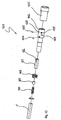
- FIG. 10 shows in an exploded view, the individual parts of Schnell conference hatcht ceremonies 101 according FIG. 9a , Clearly visible together with the FIG. 9b the fact that all the items except the locking and latching elements 106, 109 are mountable from one direction, namely from behind, which simplifies the manufacture and also allows substantial savings on the cost side
- FIGS. 11a to 11e show different variants of known and commercially available bits, which could be absorbed by the inventive quick-change holder.
- FIG. 11 a is for example a bit according to DIN 3126 C
- FIG. 11b One bit according to DIN 3126 E It goes without saying that the teaching of the invention is not limited to these variants shown.
Landscapes
- Engineering & Computer Science (AREA)
- Mechanical Engineering (AREA)
- Details Of Spanners, Wrenches, And Screw Drivers And Accessories (AREA)
- Clamps And Clips (AREA)
- Fastening Of Light Sources Or Lamp Holders (AREA)
Claims (11)
- Porte-outil à serrage rapide (1, 80, 101) pour inserts de tournevis ou embouts B, comprenant un logement d'embout (2, 2', 102) avec une région avant à six pans creux (23) intérieur pour recevoir par engagement dynamométrique des embouts B, des moyens d'éjection (3, 3', 4, 31, 81, 103, 110, 131) étant prévus à l'intérieur du logement d'embout (2, 2', 102), lesquels sont précontraints dans la direction axiale par l'embout inséré, un blocage dans une position de retenue étant réalisé par la coopération de moyens de blocage (6, 6', 106) avec les moyens d'éjection (3, 3', 4, 31, 81, 103, 110, 131) de telle sorte que l'embout inséré soit essentiellement exempt de forces de précontrainte et que les moyens d'éjection (3, 3', 4, 31, 81, 103, 110, 131) comprennent au moins un premier et un deuxième aimant permanent (3, 3', 4) qui sont disposés de telle sorte qu'ils se repoussent, ou que les moyens d'éjection comprennent un éjecteur (103) sollicité par une force de ressort, caractérisé en ce qu'un élément de blocage en forme de bille (6, 6', 106) vient en prise avec une rainure de blocage (32, 32', 132) du premier aimant mobile axialement (3, 3') ou de l'éjecteur (103), la rainure de blocage (32, 32') présentant un rayon constant R, qui correspond essentiellement au rayon de la bille de blocage (6, 6', 106) et la profondeur de la rainure (32, 32', 132) diminuant de manière constante depuis l'extrémité avant (54) jusqu'à l'extrémité arrière (55), de sorte que la bille de blocage (6, 6', 106) dans une position de blocage radialement interne bloque l'aimant (3, 3') ou l'éjecteur (103) dans une position de retenue arrière et, dans une position de libération radialement extérieure, permette à l'aimant (3, 3') ou à l'éjecteur (103) de se déplacer dans une position de déchargement avant.
- Porte-outil à serrage rapide (1, 80) selon la revendication 1, caractérisé en ce que l'aimant d'éjection (3) est disposé dans un siège cylindrique (31), de sorte que la rainure de blocage (32) soit disposée sur une surface d'enveloppe extérieure du siège (31).
- Porte-outil à serrage rapide (1, 80, 101) selon la revendication 1 ou 2, caractérisé en ce que le diamètre de la bille de blocage (6, 6', 106) est adapté aux diamètres de l'aimant d'éjection (3, 3') ou du siège cylindrique (31, 81, 131) de l'aimant d'éjection (3, 3') ou de l'éjecteur (103), à l'épaisseur de paroi du logement (2, 2', 102) dans une région de transition (24) et au diamètre intérieur d'une douille d'éjection (5, 5', 105) dans une région d'encoche (56, 156) de telle sorte que dans une position prête à la réception, l'aimant d'éjection (3, 3') ou l'éjecteur (103) ainsi que la douille (5, 5', 105) sont maintenus dans une position avant.
- Porte-outil à serrage rapide (1) selon l'une quelconque des revendications 1 à 3, caractérisé en ce que le six pans creux (23) intérieur et un alésage cylindrique (22) se chevauchent dans une région centrale, les diamètres de l'alésage (22) et la dimension du six pans creux intérieur étant ajustés l'un à l'autre de telle sorte qu'à l'extrémité frontale avant de la région de chevauchement soient réalisées six faces de butée (25) orientées vers l'arrière, contre lesquelles le côté frontal avant de l'aimant (3, 3') et/ou du siège de l'aimant (31, 81) ou d'une bague d'espacement (82) peut venir en butée.
- Porte-outil à serrage rapide (1, 80, 101) selon l'une quelconque des revendications 1 à 4, caractérisé en ce que dans la région avant du six pans creux intérieur, une rainure tangentielle (27) constitue une fenêtre (27') pour recevoir un élément d'encliquetage (9, 9', 9", 109) dans le six pans creux (23) intérieur, ou en ce que dans au moins une région de coin dans la région avant du six pans creux intérieur, au moins un alésage radial (29', 29", 129) constitue une fenêtre pour recevoir un élément d'encliquetage (9, 9', 9", 109) dans le six pans creux intérieur.
- Porte-outil à serrage rapide (1, 80, 101) selon la revendication 5, caractérisé en ce que la douille (5, 5', 105) présente un cône interne (53) dans la région de la rainure tangentielle (27) ou de l'au moins un alésage radial (29', 29", 129), de sorte que le cône interne (53), lors du déplacement axial de la douille (5, 5', 105) vers l'arrière vers le côté d'entraînement, presse un élément d'encliquetage (9, 9', 109) monté de manière mobile en translation radiale dans la rainure tangentielle (27) ou l'alésage radial (29', 29", 129), à travers la fenêtre (27') dans la région du six pans creux intérieur, où il vient en prise dans une encoche du six pans creux extérieur d'un embout à retenir.
- Porte-outil à serrage rapide (1) selon l'une quelconque des revendications 1 à 4, caractérisé en ce que dans la région avant du six pans creux intérieur, deux alésages radiaux (29', 29", 129) pour recevoir de manière mobile en translation radiale des éléments d'encliquetage (9', 9", 109) sont espacés axialement l'un de l'autre et sont disposés de manière décalée l'un de l'autre radialement de 60°.
- Porte-outil à serrage rapide (1) selon l'une quelconque des revendications 1 à 4, caractérisé en ce que dans la région avant du six pans creux intérieur, deux alésages radiaux (29', 29", 129) pour recevoir de manière mobile en translation radiale des éléments d'encliquetage (9', 9", 109) sont espacés axialement l'un de l'autre et sont disposés de manière décalée l'un de l'autre radialement de 60°.
- Porte-outil à serrage rapide (1) selon la revendication 8, caractérisé en ce que la bague d'espacement (60, 82) est pourvue d'une limitation de course.
- Porte-outil à serrage rapide (1) selon la revendication 8 ou 9, caractérisé en ce que la bague d'espacement (82) est disposée d'une seule pièce avec le siège cylindrique (81) de l'aimant d'éjection (3').
- Porte-outil à serrage rapide (1) selon l'une quelconque des revendications 8 à 10, caractérisé en ce que la bague d'espacement (60, 82) présente une région centrale libre pour recevoir les pointes de travail non requises respectives de ce qu'on appelle des doubles embouts B'.
Applications Claiming Priority (2)
| Application Number | Priority Date | Filing Date | Title |
|---|---|---|---|
| CH00332/06A CH704836B1 (de) | 2006-03-02 | 2006-03-02 | Schnellwechselhalter für Schraubendrehereinsätze. |
| PCT/CH2007/000107 WO2007098633A1 (fr) | 2006-03-02 | 2007-03-02 | Porte-outil à serrage rapide destiné à des inserts de tournevis |
Publications (2)
| Publication Number | Publication Date |
|---|---|
| EP1993787A1 EP1993787A1 (fr) | 2008-11-26 |
| EP1993787B1 true EP1993787B1 (fr) | 2010-05-05 |
Family
ID=38175639
Family Applications (1)
| Application Number | Title | Priority Date | Filing Date |
|---|---|---|---|
| EP07701907A Not-in-force EP1993787B1 (fr) | 2006-03-02 | 2007-03-02 | Porte-outil à serrage rapide destiné à des inserts de tournevis |
Country Status (5)
| Country | Link |
|---|---|
| EP (1) | EP1993787B1 (fr) |
| AT (1) | ATE466694T1 (fr) |
| CH (1) | CH704836B1 (fr) |
| DE (1) | DE502007003658D1 (fr) |
| WO (1) | WO2007098633A1 (fr) |
Cited By (1)
| Publication number | Priority date | Publication date | Assignee | Title |
|---|---|---|---|---|
| CN111515900A (zh) * | 2020-04-15 | 2020-08-11 | 安徽正兴和光电科技有限公司 | 一种用于电网检修的螺母紧固装置 |
Families Citing this family (4)
| Publication number | Priority date | Publication date | Assignee | Title |
|---|---|---|---|---|
| TWI554367B (zh) * | 2015-12-18 | 2016-10-21 | 陳河田 | 具快脫反轉結構之起子頭接桿 |
| CN109318072B (zh) * | 2018-09-28 | 2020-09-01 | 江苏柯润玺医疗科技发展有限公司 | 工件的毛刺研磨装置及其研磨方法 |
| KR200490523Y1 (ko) * | 2019-09-20 | 2019-11-26 | 이재열 | 홀딩 겸용 자화기 |
| CN111376172B (zh) * | 2020-04-27 | 2024-07-23 | 河北工业大学 | 一种用于打磨机器人的自动换刀装置 |
Family Cites Families (10)
| Publication number | Priority date | Publication date | Assignee | Title |
|---|---|---|---|---|
| US6457916B2 (en) * | 1999-11-15 | 2002-10-01 | Insty-Bit, Inc. | Locking quick-change chuck assembly |
| EP1294514A4 (fr) * | 2000-06-09 | 2007-02-14 | Jore Corp | Adaptateur de piece pour outil electrique |
| US6966562B1 (en) * | 2001-05-31 | 2005-11-22 | Wienhold James L | Multiple mode chuck |
| DE20201012U1 (de) * | 2002-01-24 | 2002-05-08 | Wiha Werkzeuge GmbH, 78136 Schonach | Halterung für Schraubendrehereinsätze |
| US6666114B1 (en) * | 2003-01-27 | 2003-12-23 | Lin Peng-Ho | Magnetic connecting tube for a screwdriver head |
| US20040164503A1 (en) * | 2003-02-21 | 2004-08-26 | Wei-Chuan Fan-Chiang | Bit quick-release device |
| US6973858B2 (en) * | 2003-08-29 | 2005-12-13 | Jung-Chih Huang | Socket assembly that can be mounted and detached quickly |
| DE202006006967U1 (de) * | 2006-05-02 | 2006-07-06 | Jeoutay Liu Industrial Co., Ltd., Ta Li | Magnetisches Ansatzrohr für eine Schraubendreherspitze |
| TWM308146U (en) * | 2006-09-25 | 2007-03-21 | Jeoutay Liu Ind Co Ltd | Structure of coupling sleeve |
| TWM313044U (en) * | 2006-11-23 | 2007-06-01 | Jeoutay Liu Ind Co Ltd | Tool bit adaptor |
-
2006
- 2006-03-02 CH CH00332/06A patent/CH704836B1/de not_active IP Right Cessation
-
2007
- 2007-03-02 AT AT07701907T patent/ATE466694T1/de active
- 2007-03-02 DE DE502007003658T patent/DE502007003658D1/de active Active
- 2007-03-02 EP EP07701907A patent/EP1993787B1/fr not_active Not-in-force
- 2007-03-02 WO PCT/CH2007/000107 patent/WO2007098633A1/fr not_active Ceased
Cited By (2)
| Publication number | Priority date | Publication date | Assignee | Title |
|---|---|---|---|---|
| CN111515900A (zh) * | 2020-04-15 | 2020-08-11 | 安徽正兴和光电科技有限公司 | 一种用于电网检修的螺母紧固装置 |
| CN111515900B (zh) * | 2020-04-15 | 2021-08-06 | 国网上海市电力公司 | 一种用于电网检修的螺母紧固装置 |
Also Published As
| Publication number | Publication date |
|---|---|
| DE502007003658D1 (de) | 2010-06-17 |
| CH704836B1 (de) | 2012-10-31 |
| EP1993787A1 (fr) | 2008-11-26 |
| ATE466694T1 (de) | 2010-05-15 |
| WO2007098633A1 (fr) | 2007-09-07 |
Similar Documents
| Publication | Publication Date | Title |
|---|---|---|
| DE602005003595T2 (de) | Werkzeuglose Blattspannvorrichtung für hin- und hergehendes Werkzeug | |
| DE60013812T2 (de) | Schnellkupplung | |
| DE19581725B4 (de) | Spannfutter | |
| DE10261748B4 (de) | Stanzwerkzeug | |
| DE69528980T2 (de) | Bohrfutter | |
| EP1009595B1 (fr) | Systeme d'outil accouplable a l'arbre d'entrainement d'un tour | |
| DE10249179B4 (de) | Spannfutter mit Schnellwechselmechanismus | |
| DE19937819B4 (de) | Spannfutter mit Verschlusshülse | |
| EP0494400A2 (fr) | Outil à main avec porte-outil détachable | |
| DE202007000115U1 (de) | Vorrichtung zum Verriegeln und Lösen einer Schraubspitze | |
| EP1447195B1 (fr) | Dispositif de forage avec un foret tubulaire | |
| EP3962697A1 (fr) | Appareil accessoire destiné à une machine-outil à main | |
| DE19951264A1 (de) | Werkzeugmaschine mit vereinfachtem Werkzeugwechsel | |
| DE69503272T2 (de) | Werkzeughalter für einen Bohrhammer und/oder Meisselhammer | |
| DE4141916C2 (de) | Vorrichtung zum Eindrehen und Setzen von selbstbohrenden Zugblindnieten | |
| EP1993787A1 (fr) | Porte-outil à serrage rapide destiné à des inserts de tournevis | |
| DE102020115087A1 (de) | Handgriffvorrichtung für eine Hand-Werkzeugmaschine | |
| WO1999056919A1 (fr) | Machine-outil a changement d'outil | |
| DE10013984A1 (de) | Werkzeugmaschine mit vereinfachtem Werkzeugwechsel | |
| EP1599315A1 (fr) | Ebarbeur | |
| EP1122032B1 (fr) | Mandrin de serrage pour des extrémités de tiges d'outils, en particulier pour lames de tournevis | |
| DE20201012U1 (de) | Halterung für Schraubendrehereinsätze | |
| EP1140431A1 (fr) | Mandrin de serrage destine a des composants d'outil | |
| DE102018002323A1 (de) | Abziehvorrichtung zum Abziehen eines Werkstücks aus einer Montageposition | |
| DE102004011579B4 (de) | Spannfutter für Werkzeugeinsätze |
Legal Events
| Date | Code | Title | Description |
|---|---|---|---|
| PUAI | Public reference made under article 153(3) epc to a published international application that has entered the european phase |
Free format text: ORIGINAL CODE: 0009012 |
|
| 17P | Request for examination filed |
Effective date: 20081002 |
|
| AK | Designated contracting states |
Kind code of ref document: A1 Designated state(s): AT BE BG CH CY CZ DE DK EE ES FI FR GB GR HU IE IS IT LI LT LU LV MC MT NL PL PT RO SE SI SK TR |
|
| 17Q | First examination report despatched |
Effective date: 20090128 |
|
| GRAP | Despatch of communication of intention to grant a patent |
Free format text: ORIGINAL CODE: EPIDOSNIGR1 |
|
| GRAS | Grant fee paid |
Free format text: ORIGINAL CODE: EPIDOSNIGR3 |
|
| DAX | Request for extension of the european patent (deleted) | ||
| GRAA | (expected) grant |
Free format text: ORIGINAL CODE: 0009210 |
|
| AK | Designated contracting states |
Kind code of ref document: B1 Designated state(s): AT BE BG CH CY CZ DE DK EE ES FI FR GB GR HU IE IS IT LI LT LU LV MC MT NL PL PT RO SE SI SK TR |
|
| REG | Reference to a national code |
Ref country code: GB Ref legal event code: FG4D Free format text: NOT ENGLISH |
|
| REG | Reference to a national code |
Ref country code: CH Ref legal event code: NV Representative=s name: RENTSCH & PARTNER Ref country code: CH Ref legal event code: EP |
|
| REG | Reference to a national code |
Ref country code: IE Ref legal event code: FG4D Free format text: LANGUAGE OF EP DOCUMENT: GERMAN |
|
| REF | Corresponds to: |
Ref document number: 502007003658 Country of ref document: DE Date of ref document: 20100617 Kind code of ref document: P |
|
| REG | Reference to a national code |
Ref country code: NL Ref legal event code: VDEP Effective date: 20100505 |
|
| LTIE | Lt: invalidation of european patent or patent extension |
Effective date: 20100505 |
|
| PG25 | Lapsed in a contracting state [announced via postgrant information from national office to epo] |
Ref country code: LT Free format text: LAPSE BECAUSE OF FAILURE TO SUBMIT A TRANSLATION OF THE DESCRIPTION OR TO PAY THE FEE WITHIN THE PRESCRIBED TIME-LIMIT Effective date: 20100505 Ref country code: SE Free format text: LAPSE BECAUSE OF FAILURE TO SUBMIT A TRANSLATION OF THE DESCRIPTION OR TO PAY THE FEE WITHIN THE PRESCRIBED TIME-LIMIT Effective date: 20100505 Ref country code: NL Free format text: LAPSE BECAUSE OF FAILURE TO SUBMIT A TRANSLATION OF THE DESCRIPTION OR TO PAY THE FEE WITHIN THE PRESCRIBED TIME-LIMIT Effective date: 20100505 Ref country code: ES Free format text: LAPSE BECAUSE OF FAILURE TO SUBMIT A TRANSLATION OF THE DESCRIPTION OR TO PAY THE FEE WITHIN THE PRESCRIBED TIME-LIMIT Effective date: 20100816 |
|
| PG25 | Lapsed in a contracting state [announced via postgrant information from national office to epo] |
Ref country code: FI Free format text: LAPSE BECAUSE OF FAILURE TO SUBMIT A TRANSLATION OF THE DESCRIPTION OR TO PAY THE FEE WITHIN THE PRESCRIBED TIME-LIMIT Effective date: 20100505 Ref country code: IS Free format text: LAPSE BECAUSE OF FAILURE TO SUBMIT A TRANSLATION OF THE DESCRIPTION OR TO PAY THE FEE WITHIN THE PRESCRIBED TIME-LIMIT Effective date: 20100905 Ref country code: LV Free format text: LAPSE BECAUSE OF FAILURE TO SUBMIT A TRANSLATION OF THE DESCRIPTION OR TO PAY THE FEE WITHIN THE PRESCRIBED TIME-LIMIT Effective date: 20100505 Ref country code: SI Free format text: LAPSE BECAUSE OF FAILURE TO SUBMIT A TRANSLATION OF THE DESCRIPTION OR TO PAY THE FEE WITHIN THE PRESCRIBED TIME-LIMIT Effective date: 20100505 |
|
| REG | Reference to a national code |
Ref country code: IE Ref legal event code: FD4D |
|
| PG25 | Lapsed in a contracting state [announced via postgrant information from national office to epo] |
Ref country code: PL Free format text: LAPSE BECAUSE OF FAILURE TO SUBMIT A TRANSLATION OF THE DESCRIPTION OR TO PAY THE FEE WITHIN THE PRESCRIBED TIME-LIMIT Effective date: 20100505 Ref country code: CY Free format text: LAPSE BECAUSE OF FAILURE TO SUBMIT A TRANSLATION OF THE DESCRIPTION OR TO PAY THE FEE WITHIN THE PRESCRIBED TIME-LIMIT Effective date: 20100602 |
|
| PG25 | Lapsed in a contracting state [announced via postgrant information from national office to epo] |
Ref country code: DK Free format text: LAPSE BECAUSE OF FAILURE TO SUBMIT A TRANSLATION OF THE DESCRIPTION OR TO PAY THE FEE WITHIN THE PRESCRIBED TIME-LIMIT Effective date: 20100505 Ref country code: PT Free format text: LAPSE BECAUSE OF FAILURE TO SUBMIT A TRANSLATION OF THE DESCRIPTION OR TO PAY THE FEE WITHIN THE PRESCRIBED TIME-LIMIT Effective date: 20100906 Ref country code: EE Free format text: LAPSE BECAUSE OF FAILURE TO SUBMIT A TRANSLATION OF THE DESCRIPTION OR TO PAY THE FEE WITHIN THE PRESCRIBED TIME-LIMIT Effective date: 20100505 Ref country code: IE Free format text: LAPSE BECAUSE OF FAILURE TO SUBMIT A TRANSLATION OF THE DESCRIPTION OR TO PAY THE FEE WITHIN THE PRESCRIBED TIME-LIMIT Effective date: 20100505 |
|
| PG25 | Lapsed in a contracting state [announced via postgrant information from national office to epo] |
Ref country code: CZ Free format text: LAPSE BECAUSE OF FAILURE TO SUBMIT A TRANSLATION OF THE DESCRIPTION OR TO PAY THE FEE WITHIN THE PRESCRIBED TIME-LIMIT Effective date: 20100505 Ref country code: RO Free format text: LAPSE BECAUSE OF FAILURE TO SUBMIT A TRANSLATION OF THE DESCRIPTION OR TO PAY THE FEE WITHIN THE PRESCRIBED TIME-LIMIT Effective date: 20100505 Ref country code: SK Free format text: LAPSE BECAUSE OF FAILURE TO SUBMIT A TRANSLATION OF THE DESCRIPTION OR TO PAY THE FEE WITHIN THE PRESCRIBED TIME-LIMIT Effective date: 20100505 |
|
| PLBE | No opposition filed within time limit |
Free format text: ORIGINAL CODE: 0009261 |
|
| STAA | Information on the status of an ep patent application or granted ep patent |
Free format text: STATUS: NO OPPOSITION FILED WITHIN TIME LIMIT |
|
| PG25 | Lapsed in a contracting state [announced via postgrant information from national office to epo] |
Ref country code: IT Free format text: LAPSE BECAUSE OF FAILURE TO SUBMIT A TRANSLATION OF THE DESCRIPTION OR TO PAY THE FEE WITHIN THE PRESCRIBED TIME-LIMIT Effective date: 20100505 |
|
| 26N | No opposition filed |
Effective date: 20110208 |
|
| REG | Reference to a national code |
Ref country code: DE Ref legal event code: R097 Ref document number: 502007003658 Country of ref document: DE Effective date: 20110207 |
|
| PG25 | Lapsed in a contracting state [announced via postgrant information from national office to epo] |
Ref country code: GR Free format text: LAPSE BECAUSE OF FAILURE TO SUBMIT A TRANSLATION OF THE DESCRIPTION OR TO PAY THE FEE WITHIN THE PRESCRIBED TIME-LIMIT Effective date: 20100806 |
|
| REG | Reference to a national code |
Ref country code: CH Ref legal event code: PFA Owner name: BD-WERKZEUGTECHNIK AG Free format text: BD-WERKZEUGTECHNIK AG#RAUTISTRASSE 19#8047 ZUERICH (CH) -TRANSFER TO- BD-WERKZEUGTECHNIK AG#RAUTISTRASSE 19#8047 ZUERICH (CH) |
|
| PGFP | Annual fee paid to national office [announced via postgrant information from national office to epo] |
Ref country code: GB Payment date: 20110321 Year of fee payment: 5 |
|
| BERE | Be: lapsed |
Owner name: BD-WERKZEUGTECHNIK A.G. Effective date: 20110331 |
|
| PG25 | Lapsed in a contracting state [announced via postgrant information from national office to epo] |
Ref country code: MC Free format text: LAPSE BECAUSE OF NON-PAYMENT OF DUE FEES Effective date: 20110331 |
|
| REG | Reference to a national code |
Ref country code: FR Ref legal event code: ST Effective date: 20111130 |
|
| PG25 | Lapsed in a contracting state [announced via postgrant information from national office to epo] |
Ref country code: MT Free format text: LAPSE BECAUSE OF FAILURE TO SUBMIT A TRANSLATION OF THE DESCRIPTION OR TO PAY THE FEE WITHIN THE PRESCRIBED TIME-LIMIT Effective date: 20100505 Ref country code: BE Free format text: LAPSE BECAUSE OF NON-PAYMENT OF DUE FEES Effective date: 20110331 |
|
| PG25 | Lapsed in a contracting state [announced via postgrant information from national office to epo] |
Ref country code: FR Free format text: LAPSE BECAUSE OF NON-PAYMENT OF DUE FEES Effective date: 20110331 |
|
| GBPC | Gb: european patent ceased through non-payment of renewal fee |
Effective date: 20120302 |
|
| PG25 | Lapsed in a contracting state [announced via postgrant information from national office to epo] |
Ref country code: GB Free format text: LAPSE BECAUSE OF NON-PAYMENT OF DUE FEES Effective date: 20120302 |
|
| PGFP | Annual fee paid to national office [announced via postgrant information from national office to epo] |
Ref country code: CH Payment date: 20130322 Year of fee payment: 7 |
|
| REG | Reference to a national code |
Ref country code: AT Ref legal event code: MM01 Ref document number: 466694 Country of ref document: AT Kind code of ref document: T Effective date: 20120302 |
|
| PG25 | Lapsed in a contracting state [announced via postgrant information from national office to epo] |
Ref country code: LU Free format text: LAPSE BECAUSE OF NON-PAYMENT OF DUE FEES Effective date: 20110302 |
|
| PG25 | Lapsed in a contracting state [announced via postgrant information from national office to epo] |
Ref country code: AT Free format text: LAPSE BECAUSE OF NON-PAYMENT OF DUE FEES Effective date: 20120302 |
|
| PG25 | Lapsed in a contracting state [announced via postgrant information from national office to epo] |
Ref country code: BG Free format text: LAPSE BECAUSE OF FAILURE TO SUBMIT A TRANSLATION OF THE DESCRIPTION OR TO PAY THE FEE WITHIN THE PRESCRIBED TIME-LIMIT Effective date: 20100805 Ref country code: TR Free format text: LAPSE BECAUSE OF FAILURE TO SUBMIT A TRANSLATION OF THE DESCRIPTION OR TO PAY THE FEE WITHIN THE PRESCRIBED TIME-LIMIT Effective date: 20100505 |
|
| PG25 | Lapsed in a contracting state [announced via postgrant information from national office to epo] |
Ref country code: HU Free format text: LAPSE BECAUSE OF FAILURE TO SUBMIT A TRANSLATION OF THE DESCRIPTION OR TO PAY THE FEE WITHIN THE PRESCRIBED TIME-LIMIT Effective date: 20100505 |
|
| PGFP | Annual fee paid to national office [announced via postgrant information from national office to epo] |
Ref country code: DE Payment date: 20140328 Year of fee payment: 8 |
|
| REG | Reference to a national code |
Ref country code: CH Ref legal event code: PL |
|
| PG25 | Lapsed in a contracting state [announced via postgrant information from national office to epo] |
Ref country code: CH Free format text: LAPSE BECAUSE OF NON-PAYMENT OF DUE FEES Effective date: 20140331 Ref country code: LI Free format text: LAPSE BECAUSE OF NON-PAYMENT OF DUE FEES Effective date: 20140331 |
|
| REG | Reference to a national code |
Ref country code: DE Ref legal event code: R119 Ref document number: 502007003658 Country of ref document: DE |
|
| PG25 | Lapsed in a contracting state [announced via postgrant information from national office to epo] |
Ref country code: DE Free format text: LAPSE BECAUSE OF NON-PAYMENT OF DUE FEES Effective date: 20151001 |