EP1993906B1 - Verfahren zur verteilung einer bremsleistung auf flugzeugbremsen - Google Patents
Verfahren zur verteilung einer bremsleistung auf flugzeugbremsen Download PDFInfo
- Publication number
- EP1993906B1 EP1993906B1 EP07731133A EP07731133A EP1993906B1 EP 1993906 B1 EP1993906 B1 EP 1993906B1 EP 07731133 A EP07731133 A EP 07731133A EP 07731133 A EP07731133 A EP 07731133A EP 1993906 B1 EP1993906 B1 EP 1993906B1
- Authority
- EP
- European Patent Office
- Prior art keywords
- braking
- brakes
- group
- objective
- aircraft
- Prior art date
- Legal status (The legal status is an assumption and is not a legal conclusion. Google has not performed a legal analysis and makes no representation as to the accuracy of the status listed.)
- Active
Links
Images
Classifications
-
- B—PERFORMING OPERATIONS; TRANSPORTING
- B64—AIRCRAFT; AVIATION; COSMONAUTICS
- B64C—AEROPLANES; HELICOPTERS
- B64C25/00—Alighting gear
- B64C25/32—Alighting gear characterised by elements which contact the ground or similar surface
- B64C25/42—Arrangement or adaptation of brakes
- B64C25/44—Actuating mechanisms
- B64C25/48—Actuating mechanisms differentially operated for steering purposes
-
- B—PERFORMING OPERATIONS; TRANSPORTING
- B60—VEHICLES IN GENERAL
- B60T—VEHICLE BRAKE CONTROL SYSTEMS OR PARTS THEREOF; BRAKE CONTROL SYSTEMS OR PARTS THEREOF, IN GENERAL; ARRANGEMENT OF BRAKING ELEMENTS ON VEHICLES IN GENERAL; PORTABLE DEVICES FOR PREVENTING UNWANTED MOVEMENT OF VEHICLES; VEHICLE MODIFICATIONS TO FACILITATE COOLING OF BRAKES
- B60T8/00—Arrangements for adjusting wheel-braking force to meet varying vehicular or ground-surface conditions, e.g. limiting or varying distribution of braking force
- B60T8/17—Using electrical or electronic regulation means to control braking
- B60T8/1701—Braking or traction control means specially adapted for particular types of vehicles
- B60T8/1703—Braking or traction control means specially adapted for particular types of vehicles for aircrafts
-
- B—PERFORMING OPERATIONS; TRANSPORTING
- B60—VEHICLES IN GENERAL
- B60T—VEHICLE BRAKE CONTROL SYSTEMS OR PARTS THEREOF; BRAKE CONTROL SYSTEMS OR PARTS THEREOF, IN GENERAL; ARRANGEMENT OF BRAKING ELEMENTS ON VEHICLES IN GENERAL; PORTABLE DEVICES FOR PREVENTING UNWANTED MOVEMENT OF VEHICLES; VEHICLE MODIFICATIONS TO FACILITATE COOLING OF BRAKES
- B60T8/00—Arrangements for adjusting wheel-braking force to meet varying vehicular or ground-surface conditions, e.g. limiting or varying distribution of braking force
- B60T8/17—Using electrical or electronic regulation means to control braking
- B60T8/1755—Brake regulation specially adapted to control the stability of the vehicle, e.g. taking into account yaw rate or transverse acceleration in a curve
Definitions
- the invention relates to a method of distributing braking between the brakes of an aircraft.
- the aircraft of a certain importance are generally equipped with a braking computer which generates a braking effort objective in response to either a support by the pilot on the brake pedals, or in response to a selection by the pilot a certain deceleration level ("autobrake" function).
- This objective of braking force is in practice achieved by sending braking instructions to the power distribution members associated with the brakes, identical for all the brakes and which are such that the sum of the braking forces developed by the brakes in response to these braking instructions achieve the objective of braking force.
- An aircraft braking process is also known from the patent document US 2005/231031 .
- the invention relates to a distribution method for optimizing the use of the brakes.
- the brakes are used to slow down the aircraft, but also to help turn the aircraft.
- the setpoint of the brakes of a group may therefore be different from the set point of the brakes of the other group.
- brake levels are determined which maximize a simultaneous satisfaction rate of the braking objective and the yaw torque objective.
- the brakes are distributed in at least one left group and one right group symmetrical to each other.
- the yaw torque objective is preferably specified by a difference between a braking force to be achieved by the left group and a braking force to be achieved by the right group.
- the braking force objective or the yaw torque objective are estimated taking into account an action of aircraft components other than the brakes that may have an influence on a trajectory of the aircraft. .
- the invention is illustrated here with reference to an aircraft such as that of the figure 1 comprising two main wing landing gear 1G and 1D, two main fuselage landing gear 2G and 2D, and an auxiliary undercarriage 3 with steerable wheels.
- the main undercarriages 1G, 1D, 2G, 2D each carry four wheels equipped with brakes.
- the aircraft is further equipped with engines 4 and a drift 5.
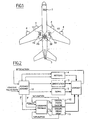
- the invention is part of an aircraft ground guidance architecture illustrated in FIG. figure 2 which comprises a module for guiding the aircraft 10.
- the guiding module 10 receives as input a trajectory setpoint (which may, where appropriate be rectilinear) and controls all the organs that can influence the trajectory on the ground of the aircraft. aircraft, that is to say the engines 4, the orientation of the wheels of the undercarriage 3, the drift 5, and, of course, the brakes of the main landing gear.
- the guidance module 10 generates commands. to the engines 4, the drift 5 and the wheel orientation control of the undercarriage 3, and deduced by difference between the trajectory setpoint and the expected effects of the actions carried out by the aforementioned members in response to said orders a braking goal F and a yaw torque goal VS to achieve by the brakes.
- the braking objective F determined from the trajectory setpoint represents a setpoint, that is to say the evolutions in time of a braking force that the brakes should develop for the aircraft to follow the trajectory according to a movement (position, speed, acceleration) given.
- the objective of braking force represents one or more brakes of duration and intensity determined. At each brake stroke, it is possible to associate a total energy to be dissipated by all the brakes of the aircraft, obtained by temporal integration of the objective of braking force.
- the goal of lace couple VS represents a setpoint, that is to say the changes in the time of the yaw torque that the brakes should develop for the aircraft to follow the trajectory according to a given movement (position, speed, acceleration).
- the yaw torque may for example be necessary to brake the aircraft in a turn.
- the brakes are controlled by a brake control module 11 which receives from the guiding module 10 the objective of braking force F and the goal of lace couple VS to achieve by the brakes.
- Dotted lines on the figure 1 illustrate the composition of the groups left 12 and right 13. It can be seen here that the groups left 12 and right 13 are symmetrical.
- the braking levels Fg and Fd are determined so that their sum is equal to the braking objective F and that their torque effect on the aircraft is equal to the yaw torque goal VS .
- the goal of yaw torque C can be specified by a difference between the effort to be developed by one of the groups and the effort to be developed by the other group.
- one or more of the brakes may only be able to generate a limited braking force, preventing the braking target F or the torque lens from being reached.
- lace VS a saturation signal is sent by the group concerned to the braking control module 11 which takes account of this saturation to generate braking levels Fg, Fd which allow to get as close to the objectives as possible.
- F , VS required given the available braking capacity.
- the brake control module 11 is programmed to prioritize the objectives, and may for example give priority to achieving the braking objective F rather than achieving the goal of yaw torque C.
- the brake control module 11 generates braking levels Fg, Fd which are adapted to meet the braking objective F, but whose The effect on the yaw torque is as close as possible, taking into account the braking capacities, the torque C objective . More generally, the braking levels Fg, Fd that will maximize a simultaneous satisfaction rate of the objectives will be sought. F , VS , considering possible limitations of one or more brakes.
- the left brake group 12 and the right brake group 13 have a mechanical action on the trajectory of the aircraft illustrated by the arrows in thick lines, as the motors 4, the steerable wheels of the undercarriage 3 and the drift 5, the action of all these organs to influence the trajectory of the aircraft.
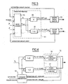
- the brake control module 11 is now detailed in relation to the figure 3 .
- the brake control module 11 firstly comprises a logic unit 15 programmed for, from the braking objective F and the required yaw torque objective C , generate a nominal force setpoint Fnom and a left / right distribution setpoint ⁇ by means of which a first modulator 20 generates the braking level Fg for the left brake group 12 and a second modulator 21 generates the braking level Fd for the right brake group.
- the braking level Fg is obtained by performing the product ⁇ .Fnom
- the braking level Fd is obtained by performing the product (1- ⁇ ) .Fnom.
- the logic unit 15 is programmed to, in the event of saturation of one or other of the groups of brakes, modulate the nominal force setpoint Fnom and the distribution setpoint ⁇ to get as close as possible to the objectives F, C, taking into account the available braking capacity.
- the brakes can exert on the aircraft a braking force and a pair of yaw. It should be noted that the distribution thus made is not fixed but varies over time.
- the knowledge of the braking level of a group makes it possible to estimate, by temporal integration of the braking level, the energy to be dissipated by the brakes of this group.
- the grouping logic of the brakes according to the invention can be pushed to a higher level by distinguishing subgroups in a group.
- a first subgroup 16 composed of the brakes equipping the main landing gear of left wing 1G
- a second subgroup 17 composed of the brakes equipping the main landing gear of the left fuselage 2G.
- the distribution control module 18 takes into account the saturation signals coming respectively from the brakes of the first subgroup 16 and the brakes of the second subgroup 17 to calculate the distribution coefficient ⁇ .
- the different braking unit forces are determined to satisfy a given operational criterion, while complying with the level of braking required, taking into account, of course, the available braking capacity.
- a thermal model of the brake is used which, as a function of energy ⁇ E k dissipated by the brake, calculates the temperature increase ⁇ T k .
- M k is the mass of the friction elements of the brake k, considered constant during braking
- Cp the heat capacity of the constituent material of the friction elements of the brake k.
- the total energy ⁇ E to be dissipated by the brakes of the group is of course equal to the sum of the energies dissipated by each brake.
- the total energy to be dissipated by the brakes is given by temporal integration of the braking force objective of the group, as already explained.
- the unit braking effort instructions Fi are deduced to be developed by each of the brakes.
- the minimization consists in calculating for each arbitrary distribution R i the corresponding energies ⁇ ⁇ E k i for each of the brakes, then the wear U k i of each of the brakes produced by the dissipation of the corresponding energy.
- Total wear U i ⁇ k U k i is the sum of the wear thus calculated.
- the minimization of the wear thus described concerns all the brakes of the same group.
- This operational criterion can be applied for each of the groups of brakes, in order to obtain a group-by-group minimization of the wear of the friction elements.
- the minimization of wear group by group can lead to a result that is not optimal from the point of view of all the brakes of the aircraft.
- the operational criterion of minimizing the wear is according to the invention generalized to be applied to all the brakes of the aircraft simultaneously, while respecting, for each group, the level of braking force required.
- the operational criterion of minimizing wear is according to the generalized invention not only for all the brakes for a given braking, but also for all the predictable braking along the trajectory. For this, it is necessary to determine in advance the predictable braking, and therefore the energy to be dissipated for each group of brakes, which requires knowing the full course likely of the aircraft on the airport.
- This knowledge can come either from the storage of the possible route (s) on the airport, or from a statistical study on a typical route for this or that airport and specifying the average number of braking operations and the average intensity of those -this.
- a movement (position, speed, acceleration) of the aircraft along this path is determined and the braking, yaw torque and energy objectives to be dissipated by the brakes are deduced therefrom.
- the selection of the distribution strategy is preferably left to the choice of the pilot. Alternatively, however, it can be automatically selected by a trajectory tracking computer. In this case, the pilot is preferably warned that one of the groups of brakes has reached saturation.
- the braking distribution according to the invention remains compatible with the implementation of an anti-slip protection for each of the braked wheels.
- the invention also covers the situation where only one of the objectives is established, for example the objective of braking force F . In this case, it is enough to arbitrarily set the yaw torque goal VS to zero.
- the operational criterion chosen for the application of braking is the minimization of the wear of the friction elements
- other operational criteria may be retained.
- the search for the distribution which leads to the application of braking force as progressive as possible in order to improve the comfort of the passengers or to preserve the operational elements of the aircraft that directly experience the braking force (the undercarriages, the fasteners of the undercarriage on the aircraft, the associated tires, etc.).
Landscapes
- Engineering & Computer Science (AREA)
- Mechanical Engineering (AREA)
- Transportation (AREA)
- Aviation & Aerospace Engineering (AREA)
- Regulating Braking Force (AREA)
- Braking Arrangements (AREA)
- Valves And Accessory Devices For Braking Systems (AREA)
Claims (5)
- Verfahren zur Verteilung einer Bremsleistung auf die Bremsen eines Luftfahrzeugs, umfassend die folgenden Schritte:- Festsetzen einer Zielvorgabe für die Bremskraft (F) und einer Zielvorgabe für das Gierbewegungs-Moment (C), das durch die Bremsen des Luftfahrzeugs realisiert werden soll;- Definieren mindestens zweier Bremsgruppen (12, 13);- Bestimmung eines Bremsniveaus (Fg, Fd) für jede Gruppe, das von besagter Gruppe realisiert werden soll, wobei die besagten Bremsniveaus so berechnet werden, dass eine gemäß dieser Bremsniveaus realisierte Bremsung zumindest unter normalen Betriebsbedingungen der Bremsen mit der Zielvorgabe für die Bremsbeanspruchung und der Zielvorgabe für das Gierbewegungs-Moment konform ist.
- Verfahren nach Anspruch 1, bei dem die Bremsniveaus bestimmt werden, die einen Grad der simultanen Erfüllung der Zielvorgabe für die Bremsung und der Zielvorgabe für das Gierbewegungs-Moment maximieren.
- Verfahren nach Anspruch 1, bei dem die Bremsen mindestens in eine linke Gruppe (12) und eine rechte Gruppe (13) eingeteilt werden, die symmetrisch zueinander sind.
- Verfahren nach Anspruch 3, bei dem die Zielvorgabe für das Gierbewegungs-Moment (C) durch eine Abweichung zwischen einer durch die linke Gruppe (12) und einer durch die rechte Gruppe (13) zu realisierenden Bremskraft spezifiziert ist.
- Verfahren nach Anspruch 1, bei dem die Zielvorgabe für die Bremskraft (F) oder die Zielvorgabe für das Gierbewegungs-Moment (C) unter Berücksichtigung einer Funktion anderer Organe des Luftfahrzeugs (3, 4, 5) als der Bremsen berechnet werden, die einen Einfluss auf eine Flugbahn des Luftfahrzeugs haben können.
Applications Claiming Priority (2)
| Application Number | Priority Date | Filing Date | Title |
|---|---|---|---|
| FR0602183A FR2898334B1 (fr) | 2006-03-13 | 2006-03-13 | Procede de repartition du freinage entre les freins d'un aeronef |
| PCT/FR2007/000437 WO2007104862A1 (fr) | 2006-03-13 | 2007-03-13 | Procédé de répartition du freinage entre les freins d'un aéronef |
Publications (2)
| Publication Number | Publication Date |
|---|---|
| EP1993906A1 EP1993906A1 (de) | 2008-11-26 |
| EP1993906B1 true EP1993906B1 (de) | 2012-11-28 |
Family
ID=37496409
Family Applications (1)
| Application Number | Title | Priority Date | Filing Date |
|---|---|---|---|
| EP07731133A Active EP1993906B1 (de) | 2006-03-13 | 2007-03-13 | Verfahren zur verteilung einer bremsleistung auf flugzeugbremsen |
Country Status (9)
| Country | Link |
|---|---|
| US (1) | US7865289B2 (de) |
| EP (1) | EP1993906B1 (de) |
| JP (1) | JP5086281B2 (de) |
| CN (1) | CN101405183B (de) |
| BR (1) | BRPI0709015B8 (de) |
| CA (1) | CA2646345C (de) |
| ES (1) | ES2399924T3 (de) |
| FR (1) | FR2898334B1 (de) |
| WO (1) | WO2007104862A1 (de) |
Families Citing this family (29)
| Publication number | Priority date | Publication date | Assignee | Title |
|---|---|---|---|---|
| US7797095B2 (en) * | 2005-02-23 | 2010-09-14 | Aviation Safety Technologies, Llc | Method and device of calculating aircraft braking friction and other relating landing performance parameters based on the data received from aircraft's on board flight data management system |
| FR2898334B1 (fr) * | 2006-03-13 | 2008-06-06 | Messier Bugatti Sa | Procede de repartition du freinage entre les freins d'un aeronef |
| JP4928221B2 (ja) * | 2006-10-18 | 2012-05-09 | 日立オートモティブシステムズ株式会社 | 車両挙動制御装置 |
| FR2918637B1 (fr) * | 2007-07-09 | 2010-01-29 | Airbus France | Systeme d'egalisation des energies de freinage. |
| FR2929019A1 (fr) | 2008-03-18 | 2009-09-25 | Airbus France Sas | Procede et dispositif de pilotage lateral d'un aeronef roulant au sol. |
| US8386094B2 (en) * | 2009-01-29 | 2013-02-26 | Hydro-Aire, Inc. | Taxi brake inhibit system |
| US8180548B2 (en) * | 2009-04-24 | 2012-05-15 | Goodrich Corporation | Deceleration controlled braking |
| US9216720B2 (en) | 2009-04-30 | 2015-12-22 | Goodrich Corporation | Differential emergency/park electric brake system |
| US8634971B2 (en) * | 2009-05-05 | 2014-01-21 | Goodrich Corporation | Brake wear control system |
| FR2959483B1 (fr) * | 2010-04-28 | 2012-06-01 | Messier Bugatti | Procede de gestion d'une liaison au sol d'un aeronef. |
| FR2965074B1 (fr) * | 2010-09-21 | 2012-08-31 | Messier Bugatti | Procede de gestion d'un mouvement au sol d'un aeronef. |
| CN102092373B (zh) * | 2010-12-16 | 2013-09-04 | 西安航空制动科技有限公司 | 一种飞机自动刹车方法及装置 |
| FR2973761B1 (fr) * | 2011-04-05 | 2013-04-05 | Messier Bugatti | Procede de repartition de couple de freinage entre des roues freinees portees par au moins un atterrisseur d'un aeronef. |
| NO344081B1 (no) * | 2012-04-02 | 2019-09-02 | FLIR Unmanned Aerial Systems AS | Fremgangsmåte og anordning for å navigere et luftfartøy |
| US8843254B2 (en) * | 2012-07-11 | 2014-09-23 | Goodrich Corporation | Systems and methods for dragging brake detection |
| CN102826018B (zh) * | 2012-09-04 | 2014-11-19 | 南车株洲电力机车研究所有限公司 | 一种列车电制动负荷分配的方法及装置 |
| FR3001438B1 (fr) * | 2013-01-30 | 2015-01-23 | Airbus Operations Sas | Procede et dispositif de pilotage lateral d'un aeronef roulant au sol. |
| GB2528317A (en) * | 2014-07-18 | 2016-01-20 | Airbus Operations Sas | Differential braking of aircraft landing gear wheels |
| CN104843175B (zh) * | 2015-04-30 | 2017-01-04 | 西安航空制动科技有限公司 | 一种采用差动刹车控制飞机极限转弯的方法 |
| GB2540183A (en) * | 2015-07-08 | 2017-01-11 | Airbus Operations Ltd | Braking control system for an aircraft |
| GB2540180A (en) | 2015-07-08 | 2017-01-11 | Airbus Operations Ltd | Data processing unit for aircraft undercarriage performance monitoring |
| CN105083542B (zh) * | 2015-07-20 | 2017-04-12 | 西安航空制动科技有限公司 | 一种采用差动刹车控制飞机最小半径极限转弯的方法 |
| GB2554097A (en) | 2016-09-20 | 2018-03-28 | Airbus Operations Ltd | Brake wear reduction apparatus |
| US10300897B2 (en) * | 2017-05-15 | 2019-05-28 | Goodrich Corporation | Brake load balance and runway centering techniques |
| GB2576937A (en) | 2018-09-07 | 2020-03-11 | Airbus Operations Ltd | Controlling aircraft wheel brakes |
| US11364884B2 (en) * | 2019-07-02 | 2022-06-21 | Goodrich Corporation | Selective braking of carbon brakes to improve life |
| US12162454B2 (en) | 2020-02-13 | 2024-12-10 | Meggitt Aircraft Braking Systems Corporation | Aircraft brake wear optimization |
| US12162456B2 (en) * | 2021-11-19 | 2024-12-10 | Goodrich Corporation | Feel adjustment braking systems and methods |
| US12365325B2 (en) * | 2023-03-13 | 2025-07-22 | GM Global Technology Operations LLC | Brake actuator control systems and methods |
Family Cites Families (20)
| Publication number | Priority date | Publication date | Assignee | Title |
|---|---|---|---|---|
| FR2372058A1 (fr) * | 1976-11-29 | 1978-06-23 | Messier Hispano Sa | Procede et dispositif de freinage automatique pour vehicules, notamment pour aeronefs |
| GB1585321A (en) * | 1978-01-18 | 1981-02-25 | Boeing Co | Brake control systems for vehicles |
| US4327413A (en) * | 1979-09-12 | 1982-04-27 | Goodyear Aerospace Corporation | Automatic brake control circuit for aircraft |
| EP0227574A2 (de) * | 1985-12-16 | 1987-07-01 | Goodyear Aerospace Corporation | Momentbegrenzungssteuerung für Antiblockiersysteme |
| US5390990A (en) * | 1993-11-24 | 1995-02-21 | Hydro-Aire Division Of Crane Company | Brake energy balancing system for multiple brake units |
| GB9503191D0 (en) * | 1995-02-18 | 1995-04-05 | Lucas Ind Plc | Torque limiter |
| JP3303605B2 (ja) * | 1995-05-17 | 2002-07-22 | トヨタ自動車株式会社 | 車輌の挙動制御装置 |
| US5785158A (en) * | 1996-02-01 | 1998-07-28 | Sundstrand Corporation | Brake apparatus with functional integrity monitor |
| US6722745B2 (en) * | 1997-05-02 | 2004-04-20 | Hydro-Aire, Inc. | System and method for adaptive brake application and initial skid detection |
| AU1682901A (en) * | 1999-11-15 | 2001-05-30 | Newtech Mecatronic Inc. | Electronic braking device |
| US6890041B1 (en) * | 2001-02-06 | 2005-05-10 | William B. Ribbens | Antilock brake systems employing a sliding mode observer based estimation of differential wheel torque |
| JP4380301B2 (ja) * | 2003-11-14 | 2009-12-09 | 日産自動車株式会社 | 車線逸脱防止装置 |
| GB0405614D0 (en) * | 2004-03-12 | 2004-04-21 | Airbus Uk Ltd | Advanced braking system |
| EP1732796B1 (de) * | 2004-03-12 | 2013-01-23 | Airbus Operations Limited | Fortschrittliches bremssystem für flugzeug |
| FR2869015B1 (fr) * | 2004-04-16 | 2006-06-30 | Airbus France Sas | Procede et dispositif pour la conduite et le freinage d'un aeronef roulant sur le sol. |
| FR2869014B1 (fr) * | 2004-04-19 | 2006-07-07 | Messier Bugatti Sa | Procede de freinage d'un aeronef a plusieurs roues freinees |
| FR2898334B1 (fr) * | 2006-03-13 | 2008-06-06 | Messier Bugatti Sa | Procede de repartition du freinage entre les freins d'un aeronef |
| US20080033607A1 (en) * | 2006-06-01 | 2008-02-07 | Bob Zeliff | Monitoring system for aircraft landing system |
| FR2927594B1 (fr) * | 2008-02-14 | 2010-04-02 | Messier Bugatti | Procede de gestion d'alimentation d'un actionneur irreversible de frein de roue de vehicule. |
| GB0806104D0 (en) * | 2008-04-04 | 2008-05-14 | Goodrich Actuation Systems Ltd | Torque limiter with brake |
-
2006
- 2006-03-13 FR FR0602183A patent/FR2898334B1/fr not_active Expired - Fee Related
-
2007
- 2007-03-13 CA CA2646345A patent/CA2646345C/fr active Active
- 2007-03-13 US US12/282,533 patent/US7865289B2/en active Active
- 2007-03-13 EP EP07731133A patent/EP1993906B1/de active Active
- 2007-03-13 ES ES07731133T patent/ES2399924T3/es active Active
- 2007-03-13 WO PCT/FR2007/000437 patent/WO2007104862A1/fr not_active Ceased
- 2007-03-13 BR BRPI0709015A patent/BRPI0709015B8/pt not_active IP Right Cessation
- 2007-03-13 JP JP2008558849A patent/JP5086281B2/ja not_active Expired - Fee Related
- 2007-03-13 CN CN2007800093199A patent/CN101405183B/zh active Active
Also Published As
| Publication number | Publication date |
|---|---|
| EP1993906A1 (de) | 2008-11-26 |
| JP5086281B2 (ja) | 2012-11-28 |
| JP2009529463A (ja) | 2009-08-20 |
| ES2399924T3 (es) | 2013-04-04 |
| US20090210126A1 (en) | 2009-08-20 |
| CN101405183B (zh) | 2011-07-27 |
| CA2646345A1 (fr) | 2007-09-20 |
| BRPI0709015B8 (pt) | 2019-07-02 |
| US7865289B2 (en) | 2011-01-04 |
| CN101405183A (zh) | 2009-04-08 |
| BRPI0709015A2 (pt) | 2011-06-21 |
| CA2646345C (fr) | 2013-06-25 |
| BRPI0709015B1 (pt) | 2019-06-18 |
| FR2898334B1 (fr) | 2008-06-06 |
| WO2007104862A1 (fr) | 2007-09-20 |
| WO2007104862A8 (fr) | 2008-10-16 |
| FR2898334A1 (fr) | 2007-09-14 |
Similar Documents
| Publication | Publication Date | Title |
|---|---|---|
| EP1993906B1 (de) | Verfahren zur verteilung einer bremsleistung auf flugzeugbremsen | |
| EP1993887B1 (de) | Verfahren zur bremskraftverteilung in mindestens einer bremsgruppe eines flugzeuges | |
| EP2137043B1 (de) | Verfahren zur unterstützung bei fahrmanövern eines fahrzeugs an einer steigung | |
| EP3938260B1 (de) | Verfahren zur erzeugung eines sollwertes für die kombinierte regelung eines radlenksystems und eines differentialbremssystems eines kraftfahrzeuges | |
| EP1935732B1 (de) | Adaptatives Bremssteurungsverfahren für Fahrzeuge | |
| CA2431361C (fr) | Procede et dispositif de commande automatique de la deceleration d'un aeronef en phase de roulement | |
| CA2581401C (fr) | Procede de gestion du freinage d'un aeronef par prevision de son deplacement sur la plateforme aeroportuaire | |
| EP2508398B1 (de) | Verfahren zur Verteilung des Bremsmoments auf die gebremsten Räder, die von mindestens einem Fahrwerk eines Luftfahrzeugs gestützt werden | |
| FR2964625A1 (fr) | Systemes et procedes pour un freinage dynamiquement stable | |
| FR3072793B1 (fr) | Ensemble d'affichage de trajectoires d'un aeronef | |
| FR3045197A1 (fr) | Procede et systeme ameliores d'aide au pilotage d'un aeronef en phase d'atterrissage | |
| EP1732794B1 (de) | Abwärtsfahrhilfeverfahren und entsprechende vorrichtung | |
| EP0592288B1 (de) | Bremsverfahren | |
| EP1555180A1 (de) | System zur Stabilitätsregelung eines Fahrzeugs mit mehreren prädiktiven Algorithmen und einem Auswahlprozess | |
| EP2746119B1 (de) | Bremssteuerungsverfahren eines Luftfahrzeugs | |
| EP2439604B1 (de) | Steuerverfahren für die Bewegung eines Flugzeugs am Boden | |
| EP1371541A1 (de) | Verfahren zum Bestimmen des Übersetzungverhältnisses einer Kraftfahrzeuglenkung | |
| FR3116500A1 (fr) | Procédé de pilotage automatisé d’un véhicule automobile | |
| FR2909463A1 (fr) | Procede et dispositif de controle actif du roulis d'un avion | |
| CA3038311C (fr) | Atterrisseur d'aeronef a bogie portant des roues freinees et au moins une roue motorisee | |
| EP1357006B1 (de) | Verfahren und Anordnung zum Optimieren der Betätigung der Feststellbremsen eines Fahrzeuges | |
| EP3150452B1 (de) | Funktionstest zur kontrolle der bewegungsbahn eines fahrzeugs mit bremsen ohne steuerung des lenkrads | |
| EP1541435B1 (de) | Verfahren zur Verzögerungsregelung eines Fahrzeugs unter Begrenzung unsymmetrisch verteilter Bremsmomente | |
| FR2801847A1 (fr) | Appareil de commande de chariot elevateur | |
| EP3150451A1 (de) | Verfahren zur kontrolle der bewegungsbahn eines fahrzeugs mit bremsen ohne steuerung des lenkrads |
Legal Events
| Date | Code | Title | Description |
|---|---|---|---|
| PUAI | Public reference made under article 153(3) epc to a published international application that has entered the european phase |
Free format text: ORIGINAL CODE: 0009012 |
|
| 17P | Request for examination filed |
Effective date: 20070926 |
|
| AK | Designated contracting states |
Kind code of ref document: A1 Designated state(s): AT BE BG CH CY CZ DE DK EE ES FI FR GB GR HU IE IS IT LI LT LU LV MC MT NL PL PT RO SE SI SK TR |
|
| 17Q | First examination report despatched |
Effective date: 20110406 |
|
| RAP1 | Party data changed (applicant data changed or rights of an application transferred) |
Owner name: MESSIER-BUGATTI-DOWTY |
|
| GRAP | Despatch of communication of intention to grant a patent |
Free format text: ORIGINAL CODE: EPIDOSNIGR1 |
|
| DAX | Request for extension of the european patent (deleted) | ||
| RIN1 | Information on inventor provided before grant (corrected) |
Inventor name: BASSET, MICHEL Inventor name: CHAMAILLARD, YANN Inventor name: DELLAC, STEPHANE Inventor name: JACQUET, ARNAUD Inventor name: GARCIA, JEAN-PIERRE Inventor name: GISSINGER, GERARD, LEON |
|
| GRAS | Grant fee paid |
Free format text: ORIGINAL CODE: EPIDOSNIGR3 |
|
| GRAA | (expected) grant |
Free format text: ORIGINAL CODE: 0009210 |
|
| AK | Designated contracting states |
Kind code of ref document: B1 Designated state(s): AT BE BG CH CY CZ DE DK EE ES FI FR GB GR HU IE IS IT LI LT LU LV MC MT NL PL PT RO SE SI SK TR |
|
| REG | Reference to a national code |
Ref country code: GB Ref legal event code: FG4D Free format text: NOT ENGLISH |
|
| REG | Reference to a national code |
Ref country code: CH Ref legal event code: EP |
|
| REG | Reference to a national code |
Ref country code: AT Ref legal event code: REF Ref document number: 586016 Country of ref document: AT Kind code of ref document: T Effective date: 20121215 |
|
| REG | Reference to a national code |
Ref country code: IE Ref legal event code: FG4D Free format text: LANGUAGE OF EP DOCUMENT: FRENCH |
|
| REG | Reference to a national code |
Ref country code: DE Ref legal event code: R096 Ref document number: 602007026981 Country of ref document: DE Effective date: 20130124 |
|
| REG | Reference to a national code |
Ref country code: ES Ref legal event code: FG2A Ref document number: 2399924 Country of ref document: ES Kind code of ref document: T3 Effective date: 20130404 |
|
| REG | Reference to a national code |
Ref country code: AT Ref legal event code: MK05 Ref document number: 586016 Country of ref document: AT Kind code of ref document: T Effective date: 20121128 |
|
| REG | Reference to a national code |
Ref country code: NL Ref legal event code: VDEP Effective date: 20121128 |
|
| REG | Reference to a national code |
Ref country code: LT Ref legal event code: MG4D |
|
| PG25 | Lapsed in a contracting state [announced via postgrant information from national office to epo] |
Ref country code: LT Free format text: LAPSE BECAUSE OF FAILURE TO SUBMIT A TRANSLATION OF THE DESCRIPTION OR TO PAY THE FEE WITHIN THE PRESCRIBED TIME-LIMIT Effective date: 20121128 Ref country code: SE Free format text: LAPSE BECAUSE OF FAILURE TO SUBMIT A TRANSLATION OF THE DESCRIPTION OR TO PAY THE FEE WITHIN THE PRESCRIBED TIME-LIMIT Effective date: 20121128 Ref country code: FI Free format text: LAPSE BECAUSE OF FAILURE TO SUBMIT A TRANSLATION OF THE DESCRIPTION OR TO PAY THE FEE WITHIN THE PRESCRIBED TIME-LIMIT Effective date: 20121128 |
|
| PG25 | Lapsed in a contracting state [announced via postgrant information from national office to epo] |
Ref country code: CY Free format text: LAPSE BECAUSE OF FAILURE TO SUBMIT A TRANSLATION OF THE DESCRIPTION OR TO PAY THE FEE WITHIN THE PRESCRIBED TIME-LIMIT Effective date: 20121128 Ref country code: SI Free format text: LAPSE BECAUSE OF FAILURE TO SUBMIT A TRANSLATION OF THE DESCRIPTION OR TO PAY THE FEE WITHIN THE PRESCRIBED TIME-LIMIT Effective date: 20121128 Ref country code: LV Free format text: LAPSE BECAUSE OF FAILURE TO SUBMIT A TRANSLATION OF THE DESCRIPTION OR TO PAY THE FEE WITHIN THE PRESCRIBED TIME-LIMIT Effective date: 20121128 Ref country code: PL Free format text: LAPSE BECAUSE OF FAILURE TO SUBMIT A TRANSLATION OF THE DESCRIPTION OR TO PAY THE FEE WITHIN THE PRESCRIBED TIME-LIMIT Effective date: 20121128 Ref country code: GR Free format text: LAPSE BECAUSE OF FAILURE TO SUBMIT A TRANSLATION OF THE DESCRIPTION OR TO PAY THE FEE WITHIN THE PRESCRIBED TIME-LIMIT Effective date: 20130301 Ref country code: PT Free format text: LAPSE BECAUSE OF FAILURE TO SUBMIT A TRANSLATION OF THE DESCRIPTION OR TO PAY THE FEE WITHIN THE PRESCRIBED TIME-LIMIT Effective date: 20130328 |
|
| PG25 | Lapsed in a contracting state [announced via postgrant information from national office to epo] |
Ref country code: AT Free format text: LAPSE BECAUSE OF FAILURE TO SUBMIT A TRANSLATION OF THE DESCRIPTION OR TO PAY THE FEE WITHIN THE PRESCRIBED TIME-LIMIT Effective date: 20121128 |
|
| PG25 | Lapsed in a contracting state [announced via postgrant information from national office to epo] |
Ref country code: CZ Free format text: LAPSE BECAUSE OF FAILURE TO SUBMIT A TRANSLATION OF THE DESCRIPTION OR TO PAY THE FEE WITHIN THE PRESCRIBED TIME-LIMIT Effective date: 20121128 Ref country code: SK Free format text: LAPSE BECAUSE OF FAILURE TO SUBMIT A TRANSLATION OF THE DESCRIPTION OR TO PAY THE FEE WITHIN THE PRESCRIBED TIME-LIMIT Effective date: 20121128 Ref country code: EE Free format text: LAPSE BECAUSE OF FAILURE TO SUBMIT A TRANSLATION OF THE DESCRIPTION OR TO PAY THE FEE WITHIN THE PRESCRIBED TIME-LIMIT Effective date: 20121128 Ref country code: DK Free format text: LAPSE BECAUSE OF FAILURE TO SUBMIT A TRANSLATION OF THE DESCRIPTION OR TO PAY THE FEE WITHIN THE PRESCRIBED TIME-LIMIT Effective date: 20121128 Ref country code: BG Free format text: LAPSE BECAUSE OF FAILURE TO SUBMIT A TRANSLATION OF THE DESCRIPTION OR TO PAY THE FEE WITHIN THE PRESCRIBED TIME-LIMIT Effective date: 20130228 |
|
| PG25 | Lapsed in a contracting state [announced via postgrant information from national office to epo] |
Ref country code: NL Free format text: LAPSE BECAUSE OF FAILURE TO SUBMIT A TRANSLATION OF THE DESCRIPTION OR TO PAY THE FEE WITHIN THE PRESCRIBED TIME-LIMIT Effective date: 20121128 Ref country code: RO Free format text: LAPSE BECAUSE OF FAILURE TO SUBMIT A TRANSLATION OF THE DESCRIPTION OR TO PAY THE FEE WITHIN THE PRESCRIBED TIME-LIMIT Effective date: 20121128 |
|
| BERE | Be: lapsed |
Owner name: MESSIER-BUGATTI-DOWTY Effective date: 20130331 |
|
| PLBE | No opposition filed within time limit |
Free format text: ORIGINAL CODE: 0009261 |
|
| STAA | Information on the status of an ep patent application or granted ep patent |
Free format text: STATUS: NO OPPOSITION FILED WITHIN TIME LIMIT |
|
| PG25 | Lapsed in a contracting state [announced via postgrant information from national office to epo] |
Ref country code: MC Free format text: LAPSE BECAUSE OF NON-PAYMENT OF DUE FEES Effective date: 20130331 |
|
| REG | Reference to a national code |
Ref country code: CH Ref legal event code: PL |
|
| 26N | No opposition filed |
Effective date: 20130829 |
|
| REG | Reference to a national code |
Ref country code: DE Ref legal event code: R097 Ref document number: 602007026981 Country of ref document: DE Effective date: 20130829 |
|
| REG | Reference to a national code |
Ref country code: IE Ref legal event code: MM4A |
|
| PG25 | Lapsed in a contracting state [announced via postgrant information from national office to epo] |
Ref country code: CH Free format text: LAPSE BECAUSE OF NON-PAYMENT OF DUE FEES Effective date: 20130331 Ref country code: BE Free format text: LAPSE BECAUSE OF NON-PAYMENT OF DUE FEES Effective date: 20130331 Ref country code: IE Free format text: LAPSE BECAUSE OF NON-PAYMENT OF DUE FEES Effective date: 20130313 Ref country code: LI Free format text: LAPSE BECAUSE OF NON-PAYMENT OF DUE FEES Effective date: 20130331 |
|
| PGFP | Annual fee paid to national office [announced via postgrant information from national office to epo] |
Ref country code: IT Payment date: 20140324 Year of fee payment: 8 |
|
| PG25 | Lapsed in a contracting state [announced via postgrant information from national office to epo] |
Ref country code: MT Free format text: LAPSE BECAUSE OF FAILURE TO SUBMIT A TRANSLATION OF THE DESCRIPTION OR TO PAY THE FEE WITHIN THE PRESCRIBED TIME-LIMIT Effective date: 20121128 |
|
| REG | Reference to a national code |
Ref country code: DE Ref legal event code: R082 Ref document number: 602007026981 Country of ref document: DE Representative=s name: SCHAUMBURG & PARTNER PATENTANWAELTE GBR, DE Ref country code: DE Ref legal event code: R082 Ref document number: 602007026981 Country of ref document: DE Representative=s name: SCHAUMBURG UND PARTNER PATENTANWAELTE MBB, DE |
|
| PG25 | Lapsed in a contracting state [announced via postgrant information from national office to epo] |
Ref country code: TR Free format text: LAPSE BECAUSE OF FAILURE TO SUBMIT A TRANSLATION OF THE DESCRIPTION OR TO PAY THE FEE WITHIN THE PRESCRIBED TIME-LIMIT Effective date: 20121128 |
|
| PG25 | Lapsed in a contracting state [announced via postgrant information from national office to epo] |
Ref country code: LU Free format text: LAPSE BECAUSE OF NON-PAYMENT OF DUE FEES Effective date: 20130313 Ref country code: HU Free format text: LAPSE BECAUSE OF FAILURE TO SUBMIT A TRANSLATION OF THE DESCRIPTION OR TO PAY THE FEE WITHIN THE PRESCRIBED TIME-LIMIT; INVALID AB INITIO Effective date: 20070313 |
|
| PG25 | Lapsed in a contracting state [announced via postgrant information from national office to epo] |
Ref country code: IT Free format text: LAPSE BECAUSE OF NON-PAYMENT OF DUE FEES Effective date: 20150313 |
|
| REG | Reference to a national code |
Ref country code: FR Ref legal event code: PLFP Year of fee payment: 10 |
|
| PG25 | Lapsed in a contracting state [announced via postgrant information from national office to epo] |
Ref country code: IS Free format text: LAPSE BECAUSE OF FAILURE TO SUBMIT A TRANSLATION OF THE DESCRIPTION OR TO PAY THE FEE WITHIN THE PRESCRIBED TIME-LIMIT Effective date: 20121128 |
|
| PGFP | Annual fee paid to national office [announced via postgrant information from national office to epo] |
Ref country code: ES Payment date: 20140327 Year of fee payment: 8 |
|
| REG | Reference to a national code |
Ref country code: FR Ref legal event code: PLFP Year of fee payment: 11 |
|
| REG | Reference to a national code |
Ref country code: FR Ref legal event code: CD Owner name: MESSIER-BUGATTI-DOWTY, FR Effective date: 20170518 |
|
| PG25 | Lapsed in a contracting state [announced via postgrant information from national office to epo] |
Ref country code: ES Free format text: LAPSE BECAUSE OF NON-PAYMENT OF DUE FEES Effective date: 20150314 |
|
| REG | Reference to a national code |
Ref country code: FR Ref legal event code: PLFP Year of fee payment: 12 |
|
| REG | Reference to a national code |
Ref country code: ES Ref legal event code: FD2A Effective date: 20180706 |
|
| PGFP | Annual fee paid to national office [announced via postgrant information from national office to epo] |
Ref country code: GB Payment date: 20220225 Year of fee payment: 16 Ref country code: DE Payment date: 20220217 Year of fee payment: 16 |
|
| REG | Reference to a national code |
Ref country code: DE Ref legal event code: R119 Ref document number: 602007026981 Country of ref document: DE |
|
| GBPC | Gb: european patent ceased through non-payment of renewal fee |
Effective date: 20230313 |
|
| PG25 | Lapsed in a contracting state [announced via postgrant information from national office to epo] |
Ref country code: GB Free format text: LAPSE BECAUSE OF NON-PAYMENT OF DUE FEES Effective date: 20230313 |
|
| PG25 | Lapsed in a contracting state [announced via postgrant information from national office to epo] |
Ref country code: GB Free format text: LAPSE BECAUSE OF NON-PAYMENT OF DUE FEES Effective date: 20230313 Ref country code: DE Free format text: LAPSE BECAUSE OF NON-PAYMENT OF DUE FEES Effective date: 20231003 |
|
| PGFP | Annual fee paid to national office [announced via postgrant information from national office to epo] |
Ref country code: FR Payment date: 20260324 Year of fee payment: 20 |