EP1993914B1 - Procede de fabrication d'un contenant du type comportant deux ou plusieurs compartiments - Google Patents
Procede de fabrication d'un contenant du type comportant deux ou plusieurs compartiments Download PDFInfo
- Publication number
- EP1993914B1 EP1993914B1 EP07730990A EP07730990A EP1993914B1 EP 1993914 B1 EP1993914 B1 EP 1993914B1 EP 07730990 A EP07730990 A EP 07730990A EP 07730990 A EP07730990 A EP 07730990A EP 1993914 B1 EP1993914 B1 EP 1993914B1
- Authority
- EP
- European Patent Office
- Prior art keywords
- compartments
- container
- separation
- sheets
- mold
- Prior art date
- Legal status (The legal status is an assumption and is not a legal conclusion. Google has not performed a legal analysis and makes no representation as to the accuracy of the status listed.)
- Active
Links
Images




Classifications
-
- B—PERFORMING OPERATIONS; TRANSPORTING
- B65—CONVEYING; PACKING; STORING; HANDLING THIN OR FILAMENTARY MATERIAL
- B65B—MACHINES, APPARATUS OR DEVICES FOR, OR METHODS OF, PACKAGING ARTICLES OR MATERIALS; UNPACKING
- B65B47/00—Apparatus or devices for forming pockets or receptacles in or from sheets, blanks, or webs, comprising essentially a die into which the material is pressed or a folding die through which the material is moved
- B65B47/08—Apparatus or devices for forming pockets or receptacles in or from sheets, blanks, or webs, comprising essentially a die into which the material is pressed or a folding die through which the material is moved by application of fluid pressure
-
- B—PERFORMING OPERATIONS; TRANSPORTING
- B29—WORKING OF PLASTICS; WORKING OF SUBSTANCES IN A PLASTIC STATE IN GENERAL
- B29C—SHAPING OR JOINING OF PLASTICS; SHAPING OF MATERIAL IN A PLASTIC STATE, NOT OTHERWISE PROVIDED FOR; AFTER-TREATMENT OF THE SHAPED PRODUCTS, e.g. REPAIRING
- B29C49/00—Blow-moulding, i.e. blowing a preform or parison to a desired shape within a mould; Apparatus therefor
- B29C49/02—Combined blow-moulding and manufacture of the preform or the parison
- B29C49/06905—Using combined techniques for making the preform
- B29C49/0691—Using combined techniques for making the preform using sheet like material, e.g. sheet blow-moulding from joined sheets
-
- B—PERFORMING OPERATIONS; TRANSPORTING
- B29—WORKING OF PLASTICS; WORKING OF SUBSTANCES IN A PLASTIC STATE IN GENERAL
- B29C—SHAPING OR JOINING OF PLASTICS; SHAPING OF MATERIAL IN A PLASTIC STATE, NOT OTHERWISE PROVIDED FOR; AFTER-TREATMENT OF THE SHAPED PRODUCTS, e.g. REPAIRING
- B29C65/00—Joining or sealing of preformed parts, e.g. welding of plastics materials; Apparatus therefor
- B29C65/76—Making non-permanent or releasable joints
-
- B—PERFORMING OPERATIONS; TRANSPORTING
- B29—WORKING OF PLASTICS; WORKING OF SUBSTANCES IN A PLASTIC STATE IN GENERAL
- B29C—SHAPING OR JOINING OF PLASTICS; SHAPING OF MATERIAL IN A PLASTIC STATE, NOT OTHERWISE PROVIDED FOR; AFTER-TREATMENT OF THE SHAPED PRODUCTS, e.g. REPAIRING
- B29C66/00—General aspects of processes or apparatus for joining preformed parts
- B29C66/01—General aspects dealing with the joint area or with the area to be joined
- B29C66/05—Particular design of joint configurations
- B29C66/10—Particular design of joint configurations particular design of the joint cross-sections
- B29C66/11—Joint cross-sections comprising a single joint-segment, i.e. one of the parts to be joined comprising a single joint-segment in the joint cross-section
- B29C66/114—Single butt joints
- B29C66/1142—Single butt to butt joints
-
- B—PERFORMING OPERATIONS; TRANSPORTING
- B29—WORKING OF PLASTICS; WORKING OF SUBSTANCES IN A PLASTIC STATE IN GENERAL
- B29C—SHAPING OR JOINING OF PLASTICS; SHAPING OF MATERIAL IN A PLASTIC STATE, NOT OTHERWISE PROVIDED FOR; AFTER-TREATMENT OF THE SHAPED PRODUCTS, e.g. REPAIRING
- B29C66/00—General aspects of processes or apparatus for joining preformed parts
- B29C66/01—General aspects dealing with the joint area or with the area to be joined
- B29C66/05—Particular design of joint configurations
- B29C66/10—Particular design of joint configurations particular design of the joint cross-sections
- B29C66/13—Single flanged joints; Fin-type joints; Single hem joints; Edge joints; Interpenetrating fingered joints; Other specific particular designs of joint cross-sections not provided for in groups B29C66/11 - B29C66/12
- B29C66/133—Fin-type joints, the parts to be joined being flexible
-
- B—PERFORMING OPERATIONS; TRANSPORTING
- B29—WORKING OF PLASTICS; WORKING OF SUBSTANCES IN A PLASTIC STATE IN GENERAL
- B29C—SHAPING OR JOINING OF PLASTICS; SHAPING OF MATERIAL IN A PLASTIC STATE, NOT OTHERWISE PROVIDED FOR; AFTER-TREATMENT OF THE SHAPED PRODUCTS, e.g. REPAIRING
- B29C66/00—General aspects of processes or apparatus for joining preformed parts
- B29C66/01—General aspects dealing with the joint area or with the area to be joined
- B29C66/05—Particular design of joint configurations
- B29C66/10—Particular design of joint configurations particular design of the joint cross-sections
- B29C66/14—Particular design of joint configurations particular design of the joint cross-sections the joint having the same thickness as the thickness of the parts to be joined
-
- B—PERFORMING OPERATIONS; TRANSPORTING
- B29—WORKING OF PLASTICS; WORKING OF SUBSTANCES IN A PLASTIC STATE IN GENERAL
- B29C—SHAPING OR JOINING OF PLASTICS; SHAPING OF MATERIAL IN A PLASTIC STATE, NOT OTHERWISE PROVIDED FOR; AFTER-TREATMENT OF THE SHAPED PRODUCTS, e.g. REPAIRING
- B29C66/00—General aspects of processes or apparatus for joining preformed parts
- B29C66/40—General aspects of joining substantially flat articles, e.g. plates, sheets or web-like materials; Making flat seams in tubular or hollow articles; Joining single elements to substantially flat surfaces
- B29C66/41—Joining substantially flat articles ; Making flat seams in tubular or hollow articles
- B29C66/43—Joining a relatively small portion of the surface of said articles
-
- B—PERFORMING OPERATIONS; TRANSPORTING
- B29—WORKING OF PLASTICS; WORKING OF SUBSTANCES IN A PLASTIC STATE IN GENERAL
- B29C—SHAPING OR JOINING OF PLASTICS; SHAPING OF MATERIAL IN A PLASTIC STATE, NOT OTHERWISE PROVIDED FOR; AFTER-TREATMENT OF THE SHAPED PRODUCTS, e.g. REPAIRING
- B29C66/00—General aspects of processes or apparatus for joining preformed parts
- B29C66/40—General aspects of joining substantially flat articles, e.g. plates, sheets or web-like materials; Making flat seams in tubular or hollow articles; Joining single elements to substantially flat surfaces
- B29C66/41—Joining substantially flat articles ; Making flat seams in tubular or hollow articles
- B29C66/43—Joining a relatively small portion of the surface of said articles
- B29C66/431—Joining the articles to themselves
- B29C66/4312—Joining the articles to themselves for making flat seams in tubular or hollow articles, e.g. transversal seams
-
- B—PERFORMING OPERATIONS; TRANSPORTING
- B29—WORKING OF PLASTICS; WORKING OF SUBSTANCES IN A PLASTIC STATE IN GENERAL
- B29C—SHAPING OR JOINING OF PLASTICS; SHAPING OF MATERIAL IN A PLASTIC STATE, NOT OTHERWISE PROVIDED FOR; AFTER-TREATMENT OF THE SHAPED PRODUCTS, e.g. REPAIRING
- B29C66/00—General aspects of processes or apparatus for joining preformed parts
- B29C66/40—General aspects of joining substantially flat articles, e.g. plates, sheets or web-like materials; Making flat seams in tubular or hollow articles; Joining single elements to substantially flat surfaces
- B29C66/41—Joining substantially flat articles ; Making flat seams in tubular or hollow articles
- B29C66/43—Joining a relatively small portion of the surface of said articles
- B29C66/432—Joining a relatively small portion of the surface of said articles for making tubular articles or closed loops, e.g. by joining several sheets ; for making hollow articles or hollow preforms
-
- B—PERFORMING OPERATIONS; TRANSPORTING
- B65—CONVEYING; PACKING; STORING; HANDLING THIN OR FILAMENTARY MATERIAL
- B65B—MACHINES, APPARATUS OR DEVICES FOR, OR METHODS OF, PACKAGING ARTICLES OR MATERIALS; UNPACKING
- B65B29/00—Packaging of materials presenting special problems
- B65B29/10—Packaging two or more different substances isolated from one another in the package but capable of being mixed without opening the package, e.g. forming packages containing a resin and hardener isolated by a frangible partition
-
- B—PERFORMING OPERATIONS; TRANSPORTING
- B29—WORKING OF PLASTICS; WORKING OF SUBSTANCES IN A PLASTIC STATE IN GENERAL
- B29C—SHAPING OR JOINING OF PLASTICS; SHAPING OF MATERIAL IN A PLASTIC STATE, NOT OTHERWISE PROVIDED FOR; AFTER-TREATMENT OF THE SHAPED PRODUCTS, e.g. REPAIRING
- B29C49/00—Blow-moulding, i.e. blowing a preform or parison to a desired shape within a mould; Apparatus therefor
- B29C49/42—Component parts, details or accessories; Auxiliary operations
- B29C49/48—Moulds
- B29C49/4802—Moulds with means for locally compressing part(s) of the parison in the main blowing cavity
- B29C2049/4807—Moulds with means for locally compressing part(s) of the parison in the main blowing cavity by movable mould parts in the mould halves
-
- B—PERFORMING OPERATIONS; TRANSPORTING
- B29—WORKING OF PLASTICS; WORKING OF SUBSTANCES IN A PLASTIC STATE IN GENERAL
- B29C—SHAPING OR JOINING OF PLASTICS; SHAPING OF MATERIAL IN A PLASTIC STATE, NOT OTHERWISE PROVIDED FOR; AFTER-TREATMENT OF THE SHAPED PRODUCTS, e.g. REPAIRING
- B29C49/00—Blow-moulding, i.e. blowing a preform or parison to a desired shape within a mould; Apparatus therefor
- B29C49/42—Component parts, details or accessories; Auxiliary operations
- B29C49/48—Moulds
- B29C49/4802—Moulds with means for locally compressing part(s) of the parison in the main blowing cavity
-
- B—PERFORMING OPERATIONS; TRANSPORTING
- B29—WORKING OF PLASTICS; WORKING OF SUBSTANCES IN A PLASTIC STATE IN GENERAL
- B29C—SHAPING OR JOINING OF PLASTICS; SHAPING OF MATERIAL IN A PLASTIC STATE, NOT OTHERWISE PROVIDED FOR; AFTER-TREATMENT OF THE SHAPED PRODUCTS, e.g. REPAIRING
- B29C49/00—Blow-moulding, i.e. blowing a preform or parison to a desired shape within a mould; Apparatus therefor
- B29C49/42—Component parts, details or accessories; Auxiliary operations
- B29C49/48—Moulds
- B29C49/4802—Moulds with means for locally compressing part(s) of the parison in the main blowing cavity
- B29C49/4812—Moulds with means for locally compressing part(s) of the parison in the main blowing cavity and welding opposite wall parts of the parisons or preforms to each other
-
- B—PERFORMING OPERATIONS; TRANSPORTING
- B29—WORKING OF PLASTICS; WORKING OF SUBSTANCES IN A PLASTIC STATE IN GENERAL
- B29C—SHAPING OR JOINING OF PLASTICS; SHAPING OF MATERIAL IN A PLASTIC STATE, NOT OTHERWISE PROVIDED FOR; AFTER-TREATMENT OF THE SHAPED PRODUCTS, e.g. REPAIRING
- B29C66/00—General aspects of processes or apparatus for joining preformed parts
- B29C66/01—General aspects dealing with the joint area or with the area to be joined
- B29C66/05—Particular design of joint configurations
- B29C66/10—Particular design of joint configurations particular design of the joint cross-sections
- B29C66/11—Joint cross-sections comprising a single joint-segment, i.e. one of the parts to be joined comprising a single joint-segment in the joint cross-section
- B29C66/112—Single lapped joints
- B29C66/1122—Single lap to lap joints, i.e. overlap joints
-
- B—PERFORMING OPERATIONS; TRANSPORTING
- B29—WORKING OF PLASTICS; WORKING OF SUBSTANCES IN A PLASTIC STATE IN GENERAL
- B29C—SHAPING OR JOINING OF PLASTICS; SHAPING OF MATERIAL IN A PLASTIC STATE, NOT OTHERWISE PROVIDED FOR; AFTER-TREATMENT OF THE SHAPED PRODUCTS, e.g. REPAIRING
- B29C66/00—General aspects of processes or apparatus for joining preformed parts
- B29C66/01—General aspects dealing with the joint area or with the area to be joined
- B29C66/345—Progressively making the joint, e.g. starting from the middle
- B29C66/3452—Making complete joints by combining partial joints
-
- B—PERFORMING OPERATIONS; TRANSPORTING
- B29—WORKING OF PLASTICS; WORKING OF SUBSTANCES IN A PLASTIC STATE IN GENERAL
- B29C—SHAPING OR JOINING OF PLASTICS; SHAPING OF MATERIAL IN A PLASTIC STATE, NOT OTHERWISE PROVIDED FOR; AFTER-TREATMENT OF THE SHAPED PRODUCTS, e.g. REPAIRING
- B29C66/00—General aspects of processes or apparatus for joining preformed parts
- B29C66/50—General aspects of joining tubular articles; General aspects of joining long products, i.e. bars or profiled elements; General aspects of joining single elements to tubular articles, hollow articles or bars; General aspects of joining several hollow-preforms to form hollow or tubular articles
- B29C66/51—Joining tubular articles, profiled elements or bars; Joining single elements to tubular articles, hollow articles or bars; Joining several hollow-preforms to form hollow or tubular articles
- B29C66/54—Joining several hollow-preforms, e.g. half-shells, to form hollow articles, e.g. for making balls, containers; Joining several hollow-preforms, e.g. half-cylinders, to form tubular articles
-
- B—PERFORMING OPERATIONS; TRANSPORTING
- B29—WORKING OF PLASTICS; WORKING OF SUBSTANCES IN A PLASTIC STATE IN GENERAL
- B29C—SHAPING OR JOINING OF PLASTICS; SHAPING OF MATERIAL IN A PLASTIC STATE, NOT OTHERWISE PROVIDED FOR; AFTER-TREATMENT OF THE SHAPED PRODUCTS, e.g. REPAIRING
- B29C66/00—General aspects of processes or apparatus for joining preformed parts
- B29C66/80—General aspects of machine operations or constructions and parts thereof
- B29C66/83—General aspects of machine operations or constructions and parts thereof characterised by the movement of the joining or pressing tools
- B29C66/832—Reciprocating joining or pressing tools
- B29C66/8322—Joining or pressing tools reciprocating along one axis
-
- B—PERFORMING OPERATIONS; TRANSPORTING
- B29—WORKING OF PLASTICS; WORKING OF SUBSTANCES IN A PLASTIC STATE IN GENERAL
- B29C—SHAPING OR JOINING OF PLASTICS; SHAPING OF MATERIAL IN A PLASTIC STATE, NOT OTHERWISE PROVIDED FOR; AFTER-TREATMENT OF THE SHAPED PRODUCTS, e.g. REPAIRING
- B29C66/00—General aspects of processes or apparatus for joining preformed parts
- B29C66/90—Measuring or controlling the joining process
- B29C66/91—Measuring or controlling the joining process by measuring or controlling the temperature, the heat or the thermal flux
- B29C66/914—Measuring or controlling the joining process by measuring or controlling the temperature, the heat or the thermal flux by controlling or regulating the temperature, the heat or the thermal flux
- B29C66/9141—Measuring or controlling the joining process by measuring or controlling the temperature, the heat or the thermal flux by controlling or regulating the temperature, the heat or the thermal flux by controlling or regulating the temperature
- B29C66/91421—Measuring or controlling the joining process by measuring or controlling the temperature, the heat or the thermal flux by controlling or regulating the temperature, the heat or the thermal flux by controlling or regulating the temperature of the joining tools
- B29C66/91423—Measuring or controlling the joining process by measuring or controlling the temperature, the heat or the thermal flux by controlling or regulating the temperature, the heat or the thermal flux by controlling or regulating the temperature of the joining tools using joining tools having different temperature zones or using several joining tools with different temperatures
Definitions
- the present invention relates to a method of manufacturing a container, such as a primary packaging, of the type comprising two or more compartments.
- the process according to the invention can be applied, for example, to the manufacture of an indicator for controlling the storage temperature of refrigerated products such as that described in the patent WO 99/63313 .
- the temperature control device described in this patent is in the form of an envelope which consists of two compartments separated by a throat capable of opening or tearing after loading. The freezing of the liquid products contained in the compartments causes the expansion of these products which has the effect of causing the opening of the constriction separating the two compartments. Subsequently, if the ambient temperature reaches the melting temperature of the products, they resume their liquid state and will then be able to mix in the two compartments due to the lack of a sealed separation between the two compartments.
- predetermined biasing means stresses capable of breaking the separation between the compartments of the container, such as the thermal stresses which have just been described, or mechanical stresses exerted voluntarily from outside the container, such as for example, manual pressure.
- the predetermined nature of the stress concerns not only the nature of this stress (thermal, mechanical, etc.) but also the amplitude of the stress (temperature difference, amplitude of the forces, etc.).
- a medical bag having at least two compartments, made of a flexible polymer material and intended to produce medical mixtures.
- This pocket is made by welding on the edge zones of a folded flexible sheet of the polymer material while the two compartments are separated from each other by a weld which has been produced at a temperature below the welding temperature. edges.
- this weld performed at a lower temperature is more fragile and therefore tearable under the effect of a force between 5N and 20N.
- the flexible pouch thus obtained may contain two separate and separate products in each compartment and rupture of the separation weld allows the mixing of these two products for the use of the mixture thus obtained.
- this flexible pouch can be perfectly used in the medical environment to contain drug solutions, it has certain disadvantages. Indeed, this flexible pouch can be fragile during handling, on occasion of shocks or printed forces to the pocket that can result in an inadvertent rupture of the separation between the compartments leading to a mixture of products not wish.
- such a bag could not be used in the case of an indicator for controlling the storage temperature of refrigerated products, because the expansion of the contents during freezing would be absorbed by the flexibility of the material constituting the bag.
- a method of manufacturing a pocket of this type is also proposed in EP 0 972 506 wherein two sheets of plastic material in multilayer film form are superimposed and welded along their periphery while an intermediate portion separates the porch into two compartments.
- This separation portion is obtained by the adhesion of the two superposed sheets resulting from a crosslinking process under electron bombardment of the multilayer film.
- pressure applied to the bag with sufficient force breaks the adhesion and release a passage between the compartments whose contents can mix.
- undesirably applied forces during handling can lead to an inadvertent rupture of the separation.
- such a bag is not usable as an indicator for monitoring the storage temperature of refrigerated products.
- non-flexible containers having a certain rigidity such as those obtained according to the manufacturing method described in EP 1 136 230 wherein two sheets of heat-sealable material are welded to define a container cell having an opening.
- This cell is then placed in a forming mold, a forming fluid then being introduced through the opening of the cell into said cell so that it matches the inner shape of the mold while masking the weld inside the mold.
- a forming fluid does not make it possible to design a container with a separation defining compartments.
- the present invention therefore aims to provide a method of manufacturing a container, such as a primary packaging, of the type comprising at least two compartments, which can function as those described in the patents WO 99/63313 , EP 0 972 506 and EP 1424 056 but not presenting their disadvantages and which is both simple to implement and effective.
- This method provides a sealed container whose compartments are separated by a brittle separation at a predetermined bias through the use of two separate heat sealing temperatures to vary the degree of sealing between sealing and brittleness while having a form coming from the mold conferring a certain mechanical strength and rigidity.
- sheets of material preferably thermoformable rigid material, which, after the first heat-sealing step, under the effect of heat, can be deformed under pressure of a gas injected into a mold.
- the walls of the mold then being generally cold, the sheets stiffen again. Therefore, the method according to the invention makes it possible to obtain a container provided with a separation resulting from the bringing into contact with each other of parts of the opposite faces of the sheets of material in the mold and having a mechanical strength. and rigidity giving it good resistance when manipulation.
- the container obtained has sufficient deformability so that it can be applied to a mechanical or thermal pressure in order to break the separation between the compartments.
- said sheets may be strips that are cut at the time of the first soldering step.
- means for closing said container are then put in place.
- the mold is defined so as to make contact with each other of the portions of opposite faces of the sheets, during the shaping of the two sheets welded under the pressure of a gas, to form, by the second weld at said parts in contact, said or each separation between said compartments.
- the mold is shaped so as to pinch at least one location the two welded sheets in the first soldering step so that, when the gas is injected, the sheets conform to the shape of the mold by being pushed towards the walls thereof while the parts in contact, clamped by the mold form by the second weld, said or each separation between said compartments.
- the latter has at least one wall projecting towards the inside of the enclosure defined by the mold, intended to grip said sheets with either a wall arranged opposite and also projecting into the mold or with the opposite wall of said mold so that said sheets remain welded and form the separation while the blown gas pushes the two sheets against the walls of the mold and defines the compartments.
- the second weld is made after penetration of at least one matrix inside the mold, during the shaping of the container, towards the inside of the container, dragging with it at least one face of said container without tearing said face.
- the separation can be obtained by penetration of two matrices into the container by driving two faces, opposite to each other, the two faces joining to be then welded.
- a single matrix provided on the mold will penetrate into the container by driving a single side of the container and join the opposite side where the weld will be performed to seal the two sides and form the separation of the container .
- a container having two compartments is obtained.
- the mold is thus shaped to present at least one drivable matrix towards the inside of the enclosure of the mold for driving with it at least one face of said shaped container in the mold without tearing said face.
- the mold is of parallelepipedal shape, preferably rectangular or square.
- said at least one projecting wall of the mold or said at least one die of the mold used in the process according to the invention has at least one acute angle.
- the separation between said compartments will then have at least one acute angle.
- Such an acute angle is a starting break which facilitates breaking the separation after solicitation.
- the compartments are filled by means of the filling orifices, by different moist products of variable density, from liquid to dense.
- the invention also relates to a container, comprising at least two compartments, and obtained by said manufacturing process.
- said container obtained by said method of manufacturing according to the invention comprises at least two compartments separated by a fragile separation at a predetermined bias and which has at least one acute angle to facilitate the breaking of said weld after said biasing.
- This type of container is suitable, for example, for use in the control of the cold chain or the packaging of different products to be mixed after a predetermined bias of said container, while having a certain rigidity in contrast to a soft pocket.
- a first high-temperature heat seal S1 is made between two sheets 111 and 112, flexible or rigid, so as to form the perimeter of the container 1.
- the temperature S1 welding is such that it can seal the perimeter of the container in a so-called sealed manner, or resistant to a predetermined bias.
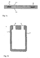
- the first heat-sealing step S1 is performed while providing openings 12 for filling the container 1, as illustrated by FIG. Fig. 1b . These filling orifices 12 are provided so as to allow future filling of the compartments of the container by the products to be packaged.
- the two welded sheets 111 and 112 are arranged in a mold 2 whose shape they conform to under the pressure of a gas injected, for example, through the filling orifices 12 (see FIG. Fig. 1b ).
- the mold 2 ' can be shaped to pinch at least one place the two sheets 111 and 112 so that, when the gas is injected, the sheets 111 and 112 conform to the shape of the mold 2' while being pushed back towards the walls thereof while the parts in contact, pinched by the mold, are welded and form the separation 14 under the effect of a heat applied at a temperature below the temperature of previous welding so that the S2 separation weld is more fragile. It was thus formed during the blowing of the gas, at least one separation 14 between two compartments 13 of the container 1 resulting from the parts of the faces of the sheets 111 and 112, clamped by the mold 2 'and welded.
- the heat applied to perform this second weld S2 may advantageously be comprised of the residual heat of the prior heat sealing step.
- the mold may thus have two walls 5 arranged projecting towards the inside of said mold 2 ', facing one another so as to clamp between them the two sheets 111 and 112 as can be seen in FIGS. Figures 1c and 1d .
- At least one die 3 penetrates inside the mold 2 and carries with it (s), without drilling, the opposite faces 11 and 12 of the container 1 which are then in contact with each other.
- a second weld S2 is formed between the two faces 11 and 12 at a temperature below the temperature of the first weld S1, temperature such that said weld S2 is fragile at a predefined bias.
- the weld S2 is said to be peelable and makes it possible to form a separation 14 consisting of the walls 141 to 144 resulting from the parts of the faces 11 and 12 which have been entrained by the matrix 3, and thus two compartments 13 of the container 1.
- said separation 14 between the compartments 13 has at least one acute angle 141.
- the wall or walls 5 of the mold (see FIG. figure 6 ) or the matrix (s) 3 used in the second step has (s) at least one acute angle.
- the wall (s) 5 or the matrix (s) 3 will allow to form a separation 14 in a configuration having at least acute angle 141 identical to the acute angle of said matrix 3.
- This acute angle 141 in the partition 14 forms a breaking primer which facilitates breaking of said second weld S2 when subjected to a predetermined bias.
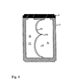
- the figure 6 represents an example of a portion of a mold 2 'in which it can be seen that the inwardly projecting wall 5 of the enclosure defined by the mold 2' has three acute angles 51 so as to form a separation in the container which will present three acute angles. On either side of the wall 5 are defined the compartments of the container.
- the other part of the mold 2 'or half-mold may be identical, the facing walls 5 then pinching the sheets 112 and 111 inserted into the mold 2'.
- the third step of the method according to the invention is the filling of said compartments 13 via the orifices 12 previously arranged during the first step of the manufacturing process of the container 1 (see FIG. Fig. 3 ).
- the products intended to be contained in a container obtained by the manufacturing method according to the invention are liquid products of density which can vary from low to high.
- closure means 4 for each of the compartments as shown in FIG. Fig. 4 .
- the closure of the container may in particular be obtained by a new high temperature thermal welding to sealing the filling orifices.
- the Fig. 4 illustrates a container 1 obtained by the manufacturing method according to the invention.
- said container 1 comprises two compartments 13 separated by a separation 14 having an acute angle 141.
- the compartments 13 contain different liquid products, respectively A and B. As illustrated by FIG. Fig. 5 these two liquid products will mix as a result of breaking the separation 14 after solicitation.
- the bias may, for example, be a thermal bias as described above.
- the freezing which has the effect of expanding the products causes the rupture of the separation 14.
- the ambient temperature reaches the melting temperature of the products, the latter resume their liquid state and will then be able to mix in the two compartments 13.
- Such a principle may, for example, be used for checking the cold chain.
- the stress can also be mechanical and obtained by pressure exerted on one of the compartments of the container, said container although rigid remaining nevertheless deformable.
- the present invention provides a simple and effective method for the manufacture of a container of the type comprising at least two compartments, said container being applicable in all areas where products, initially separated, must at a given moment be mixed.
Landscapes
- Engineering & Computer Science (AREA)
- Mechanical Engineering (AREA)
- Manufacturing & Machinery (AREA)
- Physics & Mathematics (AREA)
- Fluid Mechanics (AREA)
- Bag Frames (AREA)
- Making Paper Articles (AREA)
- Package Specialized In Special Use (AREA)
Description
- La présente invention a pour objet un procédé de fabrication d'un contenant, tel qu'un emballage primaire, du type comportant deux ou plusieurs compartiments.
- Le procédé selon l'invention peut être appliqué, par exemple, à la fabrication d'un indicateur de contrôle de la température de conservation de produits réfrigérés tel que celui qui est décrit dans le brevet
WO 99/63313 - Dans la présente description, on entendra par sollicitation prédéterminée, les contraintes capables de rompre la séparation entre les compartiments du contenant, telles que les contraintes thermiques qui viennent d'être décrites, ou des contraintes mécaniques exercées volontairement depuis l'extérieur du contenant comme, par exemple, une pression manuelle. Le caractère prédéterminé de la sollicitation concerne non seulement la nature de cette sollicitation (thermique, mécanique, etc.) mais aussi l'amplitude de la sollicitation (écart de température, amplitude des forces, etc.).
- On connaît également par le document
EP 1424 056 , une poche médicale présentant au moins deux compartiments, constituée d'un matériau polymère souple et destinée à réaliser des mélanges médicaux. Cette poche est réalisée par soudure sur les zones de bord d'une feuille souple pliée du matériau polymère tandis que les deux compartiments sont séparés l'un de l'autre par une soudure qui a été réalisée à une température inférieure à la température de soudure des bords. De cette manière, cette soudure réalisée à une température inférieure est plus fragile et donc déchirable sous l'effet d'une force comprise entre 5N et 20N. La poche souple ainsi obtenue peut contenir deux produits distincts et séparés dans chaque compartiment et la rupture de la soudure de séparation permet le mélange de ces deux produits en vue de l'utilisation du mélange ainsi obtenu. Toutefois, si une telle poche souple peut être parfaitement utilisée dans le milieu médical pour contenir des solutions médicamenteuses, elle présente certains inconvénients. En effet, cette poche souple peut s'avérer fragile lors de sa manipulation, à l'occasion de chocs ou d'efforts imprimés à la poche qui peuvent résulter en une rupture intempestive de la séparation entre les compartiments conduisant à un mélange des produits non souhaité. En outre, une telle poche ne pourrait pas être utilisable dans le cas d'un indicateur de contrôle de la température de conservation de produits réfrigérés, car la dilatation des contenus lors de la congélation serait absorbée par la souplesse du matériau constituant la poche. - Un procédé de fabrication d'une poche de ce type est également proposé dans
EP 0 972 506 dans lequel deux feuilles de matériau plastique sous forme de film multicouche sont superposées et soudées le long de leur périphérie tandis qu'une portion intermédiaire sépare la porche en deux compartiments. Cette portion de séparation est obtenue par l'adhérence des deux feuilles superposées résultant d'un procédé de réticulation sous bombardement électronique du film multicouche. Là encore, une pression appliquée sur la poche avec une force suffisante permet de rompre l'adhérence et de libérer un passage entre les compartiments dont les contenus peuvent se mélanger. Néanmoins comme dans la poche souple décrite ci-dessus, des efforts appliqués de manière non souhaitée lors de la manutention, peuvent conduire à une rupture intempestive de la séparation. De même, une telle poche n'est pas utilisable en tant qu'indicateur de contrôle de la température de conservation de produits réfrigérés. - Bien entendu, pour préserver les produits de ce type d'inconvénients liés à des chocs par exemple, on sait fabriquer des contenants non souples présentant une certaine rigidité tels que ceux obtenus selon le procédé de fabrication décrit dans
EP 1 136 230 , dans lequel on soude deux feuilles de matériaux thermoscellables pour définir une cellule de contenant ayant une ouverture. Cette cellule est ensuite placée dans un moule de formage, un fluide de formage étant ensuite introduit à travers l'ouverture de la cellule dans ladite cellule pour que celle-ci épouse la forme intérieure du moule tout en masquant la soudure à l'intérieur du contenant Toutefois, un tel procédé ne permet pas de concevoir un contenant avec une séparation définissant des compartiments. - La présente invention a donc pour but de proposer un procédé de fabrication d'un contenant, tel qu'un emballage primaire, du type comportant au moins deux compartiments, pouvant fonctionner comme ceux décrits dans les brevets
WO 99/63313 EP 0 972 506 etEP 1424 056 mais ne présentant pas leurs inconvénients et qui soit à la fois simple à mettre en oeuvre et efficace. - Pour ce faire, un procédé conforme à la présente invention est du type qui comporte les étapes suivantes :
- une première étape de soudure thermique réalisée entre deux feuilles de manière à former la périphérie du contenant et réalisée à une première température telle que ladite soudure soit résistante à une sollicitation prédéterminée, tout en ménageant des orifices de remplissage,
- une deuxième étape de soudure thermique réalisée pour former au moins une séparation entre des compartiments et réalisée à une seconde température inférieure à ladite première température et telle que ladite soudure soit fragile à ladite sollicitation,
- une troisième étape de remplissage desdits compartiments,
- Ce procédé permet d'obtenir un contenant étanche dont les compartiments sont séparés par une séparation fragile à une sollicitation prédéterminée grâce à l'utilisation de deux températures distinctes de thermo scellage permettant de faire varier le degré de scellage entre étanchéité et fragilité tout en présentant une forme venant du moule lui conférant une tenue mécanique et une rigidité certaines.
- De manière avantageuse, on utilise des feuilles de matériau, de préférence, rigide thermoformable qui, après la première étape de thermoscellage, sous l'effet de la chaleur, peuvent se déformer sous pression d'un gaz injecté dans un moule. Les parois du moule étant alors généralement froides, les feuilles se rigidifient de nouveau. Par conséquent, le procédé selon l'invention permet d'obtenir un contenant pourvu d'une séparation résultant de la mise en contact l'une avec l'autre de parties des faces opposées des feuilles de matériau dans le moule et présentant une tenue mécanique et une rigidité lui conférant une bonne résistance lors de manipulation. Toutefois, le contenant obtenu présente une déformabilité suffisante pour que l'on puisse exercer dessus une pression mécanique ou thermique en vue de rompre la séparation entre les compartiments.
- On comprendra, dans la présente invention, que lesdites feuilles peuvent être des bandes qui sont découpées au moment de la première étape de soudure.
- Selon un mode de réalisation de l'invention, on met ensuite en place des moyens de fermeture dudit contenant.
- De manière avantageuse, le moule est défini de manière à mettre en contact l'une avec l'autre des parties de faces opposées des feuilles, lors de la mise en forme des deux feuilles soudées sous la pression d'un gaz, pour former, par la deuxième soudure au niveau desdites parties en contact, ladite ou chaque séparation entre lesdits compartiments.
- Ainsi, selon une forme de réalisation, le moule est conformé de manière à pincer à au moins un endroit les deux feuilles soudées dans la première étape de soudure de sorte que, lorsque le gaz est injecté, les feuilles épousent la forme du moule en étant repoussées vers les parois de celui-ci alors que les parties en contact, pincées par le moule, forment par la deuxième soudure, ladite ou chaque séparation entre lesdits compartiments. Ainsi, lors de la mise en place des feuilles thermosoudées à leur périphérie dans le moule, celui-ci présente au moins une paroi en saillie vers l'intérieur de l'enceinte définie par le moule, destinée à pincer lesdites feuilles soit avec une paroi ménagée en regard et également saillie dans le moule soit avec la paroi opposée dudit moule de sorte que lesdites feuilles restent soudées et forment la séparation tandis que le gaz insufflé repousse les deux feuilles contre les parois du moule et définit les compartiments. En fonction du nombre de parois en saillie dans le moule, il est tout à fait possible d'ainsi former plusieurs séparations aboutissant à plus de deux compartiments pour un même contenant
- Selon une autre forme de réalisation de l'invention, la deuxième soudure est réalisée après pénétration d'au moins une matrice à l'intérieur du moule, lors de la mise en forme du contenant, vers l'intérieur du contenant, entraînant avec elle au moins une face dudit contenant sans déchirure de ladite face. Ceci aboutit à la formation de ladite ou chaque séparation entre les compartiments. Par exemple, la séparation peut être obtenue par pénétration de deux matrices vers l'intérieur du contenant en entraînant deux faces, opposées l'une à l'autre, les deux faces se rejoignant pour être alors soudées. On obtient alors un contenant comportant deux compartiments. Dans un autre exemple de réalisation, une seule matrice prévue sur le moule va pénétrer vers l'intérieur du contenant en entraînant une seule face du contenant et rejoindre la face opposée où la soudure sera réalisée pour sceller les deux faces et former la séparation du contenant. On obtient, dans ce cas également, un contenant comportant deux compartiments.
- Le moule est ainsi conformé pour présenter au moins une matrice entraînable vers l'intérieur de l'enceinte du moule pour entraîner avec elle au moins une face dudit contenant mis en forme dans le moule sans déchirure de ladite face.
- Il est tout à fait possible d'ainsi former plusieurs séparations aboutissant à plus de deux compartiments dans un même contenant
- Selon une autre caractéristique de l'invention, le moule est de forme parallélépipédique, de préférence rectangulaire ou carrée.
- Avantageusement, ladite au moins une paroi en saillie du moule ou ladite au moins une matrice du moule, utilisée dans le procédé selon l'invention présente au moins un angle aigu. De ce fait, la séparation entre lesdits compartiments présentera alors au moins un angle aigu. Un tel angle aigu constitue une amorce de rupture ce qui permet de faciliter la rupture de la séparation après sollicitation.
- Selon une autre caractéristique de l'invention, les compartiments sont remplis par l'intermédiaire des orifices de remplissage, par différents produits humides de densité variable, de liquide à dense.
- L'invention a également pour objet un contenant, comportant au moins deux compartiments, et obtenu par ledit procédé de fabrication.
- Selon un mode de réalisation de l'invention, ledit contenant obtenu par ledit procédé de fabrication selon l'invention, comporte au moins deux compartiments séparés par une séparation fragile à une sollicitation prédéterminée et qui présente au moins un angle aigu de façon à faciliter la rupture de ladite soudure après ladite sollicitation. Ce type de contenant convient, par exemple, pour une utilisation dans le contrôle de la chaîne du froid ou le conditionnement de produits différents destinés à être mélangés après une sollicitation prédéterminée dudit contenant, tout en présentant une certaine rigidité à l'inverse d'une poche souple.
- Les caractéristiques de l'invention mentionnées ci-dessus, ainsi que d'autres, apparaîtront plus clairement à la lecture de la description suivante d'exemples de réalisation, ladite description étant faite en relation avec les dessins joints, parmi lesquels :
- La Fig. la est une coupe transversale vue de côté d'un contenant obtenu après la première étape de soudure du procédé selon la présente invention,
- La
Fig. 1b est une coupe transversale vue de face d'un contenant obtenu après la première étape de soudure du procédé selon la présente invention, - La
figure 1c est une coupe transversale vue du dessus d'un moule renfermant le contenant obtenu après la première étape de soudure du procédé selon la présente invention, - La
figure 1d est une coupe transversale vue du dessus d'un moule renfermant le contenant obtenu après la deuxième étape de soudure du procédé selon la présente invention, - La
Fig. 2a est une coupe transversale vue du dessus d'un moule renfermant le contenant obtenu après la première étape de soudure d'une variante de réalisation du procédé selon la présente invention, - La
Fig. 2b est une coupe transversale vue du dessus d'un moule renfermant un contenant obtenu après la deuxième étape de soudure d'une variante de réalisation du procédé selon la présente invention, - La
Fig. 3 est une coupe transversale vue de face d'un contenant obtenu après la deuxième étape de soudure du procédé selon la présente invention, - La
Fig. 4 est une coupe transversale vue de face d'un contenant obtenu selon le procédé de la présente invention, - La
Fig. 5 est une coupe transversale vue de face d'un contenant obtenu selon le procédé de la présente invention après sollicitation et - La
Fig. 6 est une vue en plan d'un exemple de moule pour la mise en oeuvre du procédé de l'invention. - Comme illustré aux
Figures 1a et 1b , au cours de la première étape d'un procédé selon l'invention, une première soudure thermique à température dite élevée S1 est réalisée entre deux feuilles 111 et 112, souples ou rigides, de manière à former le périmètre du contenant 1. La température de la soudure S1 est telle qu'elle permet de sceller le périmètre du contenant d'une façon dite étanche, ou résistante à une sollicitation prédéterminée. - La première étape de soudure thermique S1 est réalisée tout en ménageant des orifices 12 de remplissage du contenant 1, comme l'illustre la
Fig. 1b . Ces orifices 12 de remplissage sont prévus de manière à permettre le remplissage futur des compartiments du contenant par les produits à conditionner. - A la suite de la première étape de soudure S1, les deux feuilles 111 et 112 soudées sont disposées dans un moule 2 dont elles épousent la forme sous la pression d'un gaz injecté, par exemple, par les orifices 12 de remplissage (voir
Fig. 1b ). - Selon un mode de réalisation, le moule 2' peut être conformé pour pincer à au moins un endroit les deux feuilles 111 et 112 de sorte que, lorsque le gaz est injecté, les feuilles 111 et 112 épousent la forme du moule 2' en étant repoussées vers les parois de celui-ci alors que les parties en contact, pincées par le moule, se soudent et forment la séparation 14 sous l'effet d'une chaleur appliquée à une température inférieure à la température de soudure précédente de sorte que la soudure S2 de séparation est plus fragile. On a ainsi formé lors du soufflage du gaz, au moins une séparation 14 entre deux compartiments 13 du contenant 1 résultant des parties des faces des feuilles 111 et 112, pincées par le moule 2' et soudées. La chaleur appliquée pour effectuer cette seconde soudure S2 peut être constituée de manière avantageuse de la chaleur résiduelle de l'étape de thermoscellage préalable.
- Le moule peut ainsi présenter deux parois 5 ménagées en saillie vers l'intérieur dudit moule 2', en regard l'une de l'autre de manière à pincer entre elles les deux feuilles 111 et 112 comme on peut le voir aux
figures 1c et 1d . On pourrait avoir également une seule paroi en saillie vers l'intérieur du moule venant pincer les deux feuilles 111 et 112 contre la paroi du moule 2 opposée. - Au cours d'une variante de réalisation du procédé selon l'invention, une fois, le gaz insufflé et les feuilles 111 et 112 plaquées contre les parois du moule 2, au moins une matrice 3 (dans l'exemple illustré aux
Fig. 2a et 2b , deux matrices 3) pénètre à l'intérieur du moule 2 et entraîne avec elle(s), sans les percer, les faces 11 et 12 opposées du contenant 1 qui se retrouvent alors en contact l'une avec l'autre. Là, par apport de la chaleur nécessaire, une seconde soudure S2 est réalisée entre les deux faces 11 et 12 à une température inférieure à la température de la première soudure S1, température telle que ladite soudure S2 soit fragile à une sollicitation prédéfinie. La soudure S2 est dite pelable et permet de former une séparation 14, constituée des parois 141 à 144 résultant des parties des faces 11 et 12 qui ont été entraînées par la matrice 3, et, ainsi, deux compartiments 13 du contenant 1. - De façon avantageuse, et comme représenté à la
Fig. 3 , ladite séparation 14 entre les compartiments 13 présente au moins un angle aigu 141. Pour donner à la séparation 14 une telle configuration,la ou les parois 5 du moule (voir lafigure 6 ) ou la ou les matrice(s) 3 utilisée(s) à la deuxième étape présente(nt) au moins un angle aigu. Ainsi, la ou les paroi(s) 5 ou la ou les matrice(s) 3 vont permettre de former une séparation 14 selon une configuration présentant au moins angle aigu 141 identique à l'angle aigu de ladite matrice 3. Cet angle aigu 141 dans la séparation 14 forme une amorce de rupture qui permet de faciliter la rupture de ladite deuxième soudure S2 lorsqu'elle est soumise à une sollicitation prédéterminée. - La
figure 6 représente un exemple d'une partie d'un moule 2' dans lequel on peut voir que la paroi 5 en saillie vers l'intérieur de l'enceinte définie par le moule 2' comporte trois angles aigus 51 de manière à former une séparation dans le contenant qui présentera trois angles aigus. De part et d'autre de la paroi 5 sont définis les compartiments du contenant. L'autre partie du moule2' ou demi-moule peut être identique, les parois 5 en regard pinçant alors les feuilles 112 et 111 insérées dans le moule 2'. - La troisième étape du procédé selon l'invention est le remplissage desdits compartiments 13 par l'intermédiaire des orifices 12 précédemment aménagés au cours de la première étape du procédé de fabrication du contenant 1 (voir
Fig. 3 ). Les produits destinés à être contenus dans un contenant obtenu par le procédé de fabrication selon l'invention sont des produits liquides de densité pouvant varier de faible à forte. - Enfin, il est possible de sceller le contenant en plaçant des moyens de fermeture 4 pour chacun des compartiments comme représenté à la
Fig. 4 . La fermeture du contenant peut notamment être obtenu par un nouveau soudage thermique à température élevée pour sceller de manière étanche les orifices de remplissage. - La
Fig. 4 illustre un contenant 1 obtenu par le procédé de fabrication selon l'invention. - Dans ce mode de réalisation, ledit contenant 1 comporte deux compartiments 13 sépares par une séparation 14 présentant un angle aigu 141. Les compartiments 13 contiennent des produits liquides différents, respectivement A et B. Comme l'illustre la
Fig. 5 , ces deux produits liquides vont se mélanger à la suite de la rupture de la séparation 14 après sollicitation. La sollicitation peut, par exemple, être une sollicitation thermique telle que décrite précédemment. Ainsi, la congélation qui a pour effet de dilater les produits provoque la rupture de la séparation 14. Par la suite, si la température ambiante atteint la température de fusion des produits, ces derniers reprennent leur état liquide et vont alors pouvoir se mélanger dans les deux compartiments 13. Un tel principe peut, par exemple, être utilisé pour le contrôle de la chaîne du froid. - La sollicitation peut également être mécanique et obtenue par pression exercée sur l'un des compartiments du contenant, ledit contenant bien que rigide restant malgré tout déformable.
- Ainsi, la présente invention fournit un procédé simple et efficace pour la fabrication d'un contenant du type comportant au moins deux compartiments, ledit contenant trouvant application dans tous les domaines où des produits, initialement séparés, doivent à un moment déterminé être mélangés.
Claims (8)
- Procédé de fabrication d'un contenant (1) du type comprenant deux ou plusieurs compartiments, ledit procédé comportant les étapes suivantes :- une première étape de soudure thermique (S1) réalisée entre deux feuilles (111, 112) de manière à former la périphérie du contenant et réalisée à une première température telle que ladite soudure (S1) soit résistante à une sollicitation prédéterminée, tout en ménageant des orifices de remplissage (12),- une deuxième étape de soudure thermique (S2) réalisée pour former au moins une séparation entre des compartiments (13) et réalisée à une seconde température inférieure à ladite première température et telle que ladite soudure (S2) soit fragile à ladite sollicitation,- une troisième étape de remplissage desdits compartiments (13),caractérisé en ce qu'après ladite première étape de soudure, lesdites deux feuilles soudées (111, 112) sont disposées dans un moule (2, 2') dont elles épousent la forme sous la pression d'un gaz.
- Procédé de fabrication selon la revendication 1, caractérisé en ce que l'on met en place des moyens de fermeture dudit contenant.
- Procédé de fabrication selon l'une des revendications 1 ou 2, caractérisé en ce que le moule (2, 2') est défini de manière à mettre en contact l'une avec l'autre des parties de faces opposées des feuilles (111, 112), lors de la mise en forme des deux feuilles (111, 112) soudées sous la pression d'un gaz, pour former, par la deuxième soudure (S2) au niveau desdites parties en contact, ladite ou chaque séparation entre lesdits compartiments (13).
- Procédé selon la revendication 3, caractérisé en ce que le moule (2') est conformé de manière à présenter au moins une paroi (5) en saillie vers l'intérieur du moule (2') destinée à pincer lesdites feuilles (111, 112) disposées dedans.
- Procédé de fabrication selon l'une des revendications 1 à 3, caractérisé en ce que, préalablement à ladite deuxième soudure (S2), des parties de faces opposées du contenant sont mises en contact l'une avec l'autre pour former ladite ou chaque séparation entre lesdits compartiments (13), par entraînement desdites faces opposées par l'intermédiaire d'au moins une matrice (5).
- Procédé de fabrication selon l'une quelconque des revendications précédentes, caractérisé en ce que ladite au moins une matrice (3) ou ladite au moins une paroi (5) en saillie vers l'intérieur du moule (2') présente au moins un angle aigu de manière à former au moins un angle aigu (51) sur ladite séparation (14).
- Procédé de fabrication selon l'une quelconque des revendications précédentes, caractérisé en ce que ledit moule (2) est de forme parallélépipédique, de préférence rectangulaire ou carrée.
- Procédé de fabrication selon l'une quelconque des revendications précédentes, caractérisé en ce que le remplissage des compartiments (13) est effectue au moyen de produits humides de densité variable, de faible a forte.
Applications Claiming Priority (2)
| Application Number | Priority Date | Filing Date | Title |
|---|---|---|---|
| FR0601314A FR2897342B1 (fr) | 2006-02-15 | 2006-02-15 | Procede de fabrication d'un contenant du type comportant deux ou plusieurs compartiments |
| PCT/FR2007/000279 WO2007093713A2 (fr) | 2006-02-15 | 2007-02-15 | Procede de fabrication d ' un contenant comportant deux ou plusieurs compartiments ainsi que le contenat obtenu |
Publications (2)
| Publication Number | Publication Date |
|---|---|
| EP1993914A2 EP1993914A2 (fr) | 2008-11-26 |
| EP1993914B1 true EP1993914B1 (fr) | 2011-03-23 |
Family
ID=37075805
Family Applications (1)
| Application Number | Title | Priority Date | Filing Date |
|---|---|---|---|
| EP07730990A Active EP1993914B1 (fr) | 2006-02-15 | 2007-02-15 | Procede de fabrication d'un contenant du type comportant deux ou plusieurs compartiments |
Country Status (8)
| Country | Link |
|---|---|
| US (1) | US7937912B2 (fr) |
| EP (1) | EP1993914B1 (fr) |
| AT (1) | ATE502856T1 (fr) |
| BR (1) | BRPI0707905A2 (fr) |
| CA (1) | CA2642845A1 (fr) |
| DE (1) | DE602007013366D1 (fr) |
| FR (1) | FR2897342B1 (fr) |
| WO (1) | WO2007093713A2 (fr) |
Families Citing this family (1)
| Publication number | Priority date | Publication date | Assignee | Title |
|---|---|---|---|---|
| SI2987615T1 (sl) * | 2014-08-20 | 2018-11-30 | Etimex Technical Components Gmbh | Naprava in postopek za preoblikovanje pihalne gibne cevi s pihanjem |
Family Cites Families (26)
| Publication number | Priority date | Publication date | Assignee | Title |
|---|---|---|---|---|
| US2975473A (en) * | 1953-06-17 | 1961-03-21 | Hagen Reinold | Manufacture of hollow plastic articles |
| DE1191549B (de) * | 1961-09-28 | 1965-04-22 | Formplastic G M B H | Verfahren und Vorrichtung zum fortlaufenden Herstellen von Behaeltern mit einer Standflaeche aus thermoplastischem Kunststoff |
| US3281301A (en) * | 1963-12-11 | 1966-10-25 | Us Rubber Co | Method of making rigid laminate of thermoplastic sheets having increased load-bearing ability |
| US3804077A (en) * | 1971-08-05 | 1974-04-16 | Kay Laboratories Inc | Hot or cold pack |
| US5176275A (en) * | 1989-03-27 | 1993-01-05 | Bowie Stuart S | Temperature release containers |
| IT1243064B (it) * | 1990-10-02 | 1994-05-23 | Sarong Spa | Apparecchiatura per la formatura di alveoli in nastri senza soluzione di continuita', in particolare per il confezionamento di prodotti iniettabili come supposte, ovuli o simili |
| US5500067A (en) * | 1991-10-01 | 1996-03-19 | Jenkner; Brian D. | Apparatus and methods for forming, filling and sealing fluid filled cavities |
| US5242433A (en) * | 1992-12-07 | 1993-09-07 | Creative Products Resource Associates, Ltd. | Packaging system with in-tandem applicator pads for topical drug delivery |
| US5254109A (en) * | 1992-12-07 | 1993-10-19 | Creative Products Resource Associates, Ltd. | Separately packaged applicator pads for topical delivery of incompatable drugs |
| JP3282817B2 (ja) * | 1993-01-19 | 2002-05-20 | バクスター、インターナショナル、インコーポレイテッド | マルチチャンバー容器 |
| DE4410876A1 (de) * | 1994-03-29 | 1995-10-05 | Fresenius Ag | Medizinischer Mehrkammerbeutel und Verfahren zu seiner Herstellung |
| IT1269392B (it) * | 1994-07-12 | 1997-03-26 | Unifill Spa | Metodo per la formatura di contenitori in materiale termoformabile e termosaldabile ed impianto relativo |
| US5996782A (en) * | 1997-04-14 | 1999-12-07 | Sealed Air Corporation | Foam in bag packaging system for manual use |
| US5857620A (en) * | 1997-07-14 | 1999-01-12 | The Scott Fetzer Company | Liquid dispenser with integral wick/emanator assembly |
| JPH11169432A (ja) * | 1997-12-09 | 1999-06-29 | Hosokawa Yoko:Kk | 輸液バッグ及びその製造方法 |
| IT1303144B1 (it) * | 1998-07-10 | 2000-10-30 | Haemotronic Advanced Medical T | Sacca flessibile per il contenimento di almeno due sostanze separateda miscelare per uso medico, e relativo metodo di fabbricazione |
| US6112537A (en) * | 1999-06-24 | 2000-09-05 | John A. Broadbent | Beverage container with ice compartment |
| US6547468B2 (en) * | 2001-06-22 | 2003-04-15 | The Procter & Gamble Company | Dosing reservoir |
| ATE356045T1 (de) * | 1999-11-17 | 2007-03-15 | Reckitt Benckiser Uk Ltd | Spritzgegossener wasserlöslicher behälter |
| EP1136230A1 (fr) * | 2000-03-13 | 2001-09-26 | SARONG S.p.A. | Procédé et machine pour la fabrication de récipients de matière faconnable à chaud |
| US6419118B1 (en) * | 2000-07-11 | 2002-07-16 | Blake M. Rees | Containers with flexible pouch and closure member |
| GB2374580B (en) * | 2001-04-20 | 2003-07-16 | Reckitt Benckiser | Water-soluble containers |
| ITMO20020017A1 (it) * | 2002-01-24 | 2003-07-24 | Sarong Spa | Apparecchiatura formatrice per la formatura di almeno una striscia continua di contenitori |
| TWI252203B (en) * | 2002-03-28 | 2006-04-01 | Showa Denko Plastic Product Co | Infusion container with multiple chambers and production method thereof |
| US20060003057A1 (en) * | 2002-10-21 | 2006-01-05 | Kelly Robert C | Gas-release packet with frangible sub-packet |
| US7618406B2 (en) * | 2007-01-22 | 2009-11-17 | Baxter International, Inc. | Break seal before access dual chamber bag |
-
2006
- 2006-02-15 FR FR0601314A patent/FR2897342B1/fr not_active Expired - Fee Related
-
2007
- 2007-02-15 AT AT07730990T patent/ATE502856T1/de not_active IP Right Cessation
- 2007-02-15 CA CA002642845A patent/CA2642845A1/fr not_active Abandoned
- 2007-02-15 EP EP07730990A patent/EP1993914B1/fr active Active
- 2007-02-15 WO PCT/FR2007/000279 patent/WO2007093713A2/fr not_active Ceased
- 2007-02-15 BR BRPI0707905-2A patent/BRPI0707905A2/pt not_active IP Right Cessation
- 2007-02-15 DE DE602007013366T patent/DE602007013366D1/de active Active
- 2007-02-15 US US12/279,151 patent/US7937912B2/en not_active Expired - Fee Related
Also Published As
| Publication number | Publication date |
|---|---|
| WO2007093713A3 (fr) | 2007-10-11 |
| WO2007093713A2 (fr) | 2007-08-23 |
| ATE502856T1 (de) | 2011-04-15 |
| FR2897342B1 (fr) | 2010-08-27 |
| FR2897342A1 (fr) | 2007-08-17 |
| CA2642845A1 (fr) | 2007-08-23 |
| US20090013650A1 (en) | 2009-01-15 |
| EP1993914A2 (fr) | 2008-11-26 |
| DE602007013366D1 (de) | 2011-05-05 |
| BRPI0707905A2 (pt) | 2011-07-26 |
| US7937912B2 (en) | 2011-05-10 |
Similar Documents
| Publication | Publication Date | Title |
|---|---|---|
| EP0334700B1 (fr) | Procédé permettant la fermeture puis l'ouverture de récipients stérilisables, opercules permettant la mise en oeuvre dudit procédé et procédé de fabrication desdits opercules | |
| FR2545453A1 (fr) | Emballage et son procede de fabrication | |
| US6484874B1 (en) | Medical container with multiple chambers and method of producing the same | |
| JP6265862B2 (ja) | 包装容器およびその製造方法 | |
| FR2757835A1 (fr) | Procede de fabrication d'un emballage et emballage a predecoupe laser | |
| FR2578816A1 (fr) | Emballage etanche a la pression | |
| EP0678457B1 (fr) | Conteneur avec un dispositif de fermeture comportant un clapet et un bloc de matériau thermo-fusible | |
| JP2017222369A (ja) | フィルム製容器 | |
| FR3053586A1 (fr) | Poche souple 3d a emplir pour fluides biopharmaceutiques, et procede pour realiser une telle poche | |
| FR3059229A1 (fr) | Poche souple 3d a emplir pour fluides biopharmaceutiques, et procede pour realiser une telle poche | |
| MC2162A1 (fr) | Feuille multicouche en matiere plastique pour constituer des recipients destines a etre fermes par un opercule soude,et recipient formes a partir de cette feuille | |
| EP1993914B1 (fr) | Procede de fabrication d'un contenant du type comportant deux ou plusieurs compartiments | |
| CH703963A2 (fr) | Machine de gonflage remplissage automatique de coussin de gaz, notamment d'air, pour emballage, et son utilisation pour gonfler et remplir des coussins. | |
| EP1348639A1 (fr) | Emballage pour le conditionnement de produits alimentaires et médical avec ouverture facile et refermeture | |
| MX2007015098A (es) | Un recipiente sellable, y metodo para sellar un recipiente. | |
| EP3541344B1 (fr) | Poche à usage médical à deux compartiments comportant une languette | |
| WO2018008117A1 (fr) | Sac d'emballage | |
| EP1657158B1 (fr) | Dispositif d'ouverture et/ou de fermeture d'un emballage hermétique, notamment destiné à la conservation de produits agroalimentaires | |
| EP3014165B1 (fr) | Bloc isolant sous vide | |
| JP2009018814A (ja) | 物品収容袋 | |
| WO1994025252A1 (fr) | Electrode de soudage a haute frequence pour poches multicompartiments a usage medical en film plastique, et poches realisees grace a ce materiel | |
| WO2022230588A1 (fr) | Film composite, sac d'emballage, élément opercule, contenant avec opercule et procédé de fabrication dudit film composite | |
| EP1912877B1 (fr) | Emballage souple etanche resistant a haute temperature pour produit alimentaire | |
| FR2895982A1 (fr) | Procede de fabrication d'un ensemble comprenant un recipient souple et une dose de produit alimentaire tartinable conditionnee dans le recipient. | |
| FR2731414A1 (fr) | Emballage permettant l'evacuation des surpressions internes |
Legal Events
| Date | Code | Title | Description |
|---|---|---|---|
| PUAI | Public reference made under article 153(3) epc to a published international application that has entered the european phase |
Free format text: ORIGINAL CODE: 0009012 |
|
| 17P | Request for examination filed |
Effective date: 20080912 |
|
| AK | Designated contracting states |
Kind code of ref document: A2 Designated state(s): AT BE BG CH CY CZ DE DK EE ES FI FR GB GR HU IE IS IT LI LT LU LV MC NL PL PT RO SE SI SK TR |
|
| AX | Request for extension of the european patent |
Extension state: AL BA HR MK RS |
|
| GRAP | Despatch of communication of intention to grant a patent |
Free format text: ORIGINAL CODE: EPIDOSNIGR1 |
|
| RIN1 | Information on inventor provided before grant (corrected) |
Inventor name: HARARI, CLEMENT, MARKE |
|
| GRAS | Grant fee paid |
Free format text: ORIGINAL CODE: EPIDOSNIGR3 |
|
| GRAA | (expected) grant |
Free format text: ORIGINAL CODE: 0009210 |
|
| AK | Designated contracting states |
Kind code of ref document: B1 Designated state(s): AT BE BG CH CY CZ DE DK EE ES FI FR GB GR HU IE IS IT LI LT LU LV MC NL PL PT RO SE SI SK TR |
|
| AX | Request for extension of the european patent |
Extension state: AL BA HR MK RS |
|
| REG | Reference to a national code |
Ref country code: GB Ref legal event code: FG4D Free format text: NOT ENGLISH |
|
| REG | Reference to a national code |
Ref country code: CH Ref legal event code: EP |
|
| REG | Reference to a national code |
Ref country code: IE Ref legal event code: FG4D |
|
| REF | Corresponds to: |
Ref document number: 602007013366 Country of ref document: DE Date of ref document: 20110505 Kind code of ref document: P |
|
| REG | Reference to a national code |
Ref country code: DE Ref legal event code: R096 Ref document number: 602007013366 Country of ref document: DE Effective date: 20110505 |
|
| REG | Reference to a national code |
Ref country code: NL Ref legal event code: VDEP Effective date: 20110323 |
|
| PG25 | Lapsed in a contracting state [announced via postgrant information from national office to epo] |
Ref country code: GR Free format text: LAPSE BECAUSE OF FAILURE TO SUBMIT A TRANSLATION OF THE DESCRIPTION OR TO PAY THE FEE WITHIN THE PRESCRIBED TIME-LIMIT Effective date: 20110624 Ref country code: SE Free format text: LAPSE BECAUSE OF FAILURE TO SUBMIT A TRANSLATION OF THE DESCRIPTION OR TO PAY THE FEE WITHIN THE PRESCRIBED TIME-LIMIT Effective date: 20110323 Ref country code: LV Free format text: LAPSE BECAUSE OF FAILURE TO SUBMIT A TRANSLATION OF THE DESCRIPTION OR TO PAY THE FEE WITHIN THE PRESCRIBED TIME-LIMIT Effective date: 20110323 Ref country code: LT Free format text: LAPSE BECAUSE OF FAILURE TO SUBMIT A TRANSLATION OF THE DESCRIPTION OR TO PAY THE FEE WITHIN THE PRESCRIBED TIME-LIMIT Effective date: 20110323 |
|
| LTIE | Lt: invalidation of european patent or patent extension |
Effective date: 20110323 |
|
| PG25 | Lapsed in a contracting state [announced via postgrant information from national office to epo] |
Ref country code: FI Free format text: LAPSE BECAUSE OF FAILURE TO SUBMIT A TRANSLATION OF THE DESCRIPTION OR TO PAY THE FEE WITHIN THE PRESCRIBED TIME-LIMIT Effective date: 20110323 Ref country code: SI Free format text: LAPSE BECAUSE OF FAILURE TO SUBMIT A TRANSLATION OF THE DESCRIPTION OR TO PAY THE FEE WITHIN THE PRESCRIBED TIME-LIMIT Effective date: 20110323 Ref country code: BG Free format text: LAPSE BECAUSE OF FAILURE TO SUBMIT A TRANSLATION OF THE DESCRIPTION OR TO PAY THE FEE WITHIN THE PRESCRIBED TIME-LIMIT Effective date: 20110623 Ref country code: CY Free format text: LAPSE BECAUSE OF FAILURE TO SUBMIT A TRANSLATION OF THE DESCRIPTION OR TO PAY THE FEE WITHIN THE PRESCRIBED TIME-LIMIT Effective date: 20110323 Ref country code: AT Free format text: LAPSE BECAUSE OF FAILURE TO SUBMIT A TRANSLATION OF THE DESCRIPTION OR TO PAY THE FEE WITHIN THE PRESCRIBED TIME-LIMIT Effective date: 20110323 |
|
| REG | Reference to a national code |
Ref country code: IE Ref legal event code: FD4D |
|
| PG25 | Lapsed in a contracting state [announced via postgrant information from national office to epo] |
Ref country code: PT Free format text: LAPSE BECAUSE OF FAILURE TO SUBMIT A TRANSLATION OF THE DESCRIPTION OR TO PAY THE FEE WITHIN THE PRESCRIBED TIME-LIMIT Effective date: 20110725 Ref country code: EE Free format text: LAPSE BECAUSE OF FAILURE TO SUBMIT A TRANSLATION OF THE DESCRIPTION OR TO PAY THE FEE WITHIN THE PRESCRIBED TIME-LIMIT Effective date: 20110323 |
|
| PG25 | Lapsed in a contracting state [announced via postgrant information from national office to epo] |
Ref country code: RO Free format text: LAPSE BECAUSE OF FAILURE TO SUBMIT A TRANSLATION OF THE DESCRIPTION OR TO PAY THE FEE WITHIN THE PRESCRIBED TIME-LIMIT Effective date: 20110323 Ref country code: SK Free format text: LAPSE BECAUSE OF FAILURE TO SUBMIT A TRANSLATION OF THE DESCRIPTION OR TO PAY THE FEE WITHIN THE PRESCRIBED TIME-LIMIT Effective date: 20110323 Ref country code: CZ Free format text: LAPSE BECAUSE OF FAILURE TO SUBMIT A TRANSLATION OF THE DESCRIPTION OR TO PAY THE FEE WITHIN THE PRESCRIBED TIME-LIMIT Effective date: 20110323 Ref country code: ES Free format text: LAPSE BECAUSE OF FAILURE TO SUBMIT A TRANSLATION OF THE DESCRIPTION OR TO PAY THE FEE WITHIN THE PRESCRIBED TIME-LIMIT Effective date: 20110704 Ref country code: IS Free format text: LAPSE BECAUSE OF FAILURE TO SUBMIT A TRANSLATION OF THE DESCRIPTION OR TO PAY THE FEE WITHIN THE PRESCRIBED TIME-LIMIT Effective date: 20110723 |
|
| PG25 | Lapsed in a contracting state [announced via postgrant information from national office to epo] |
Ref country code: NL Free format text: LAPSE BECAUSE OF FAILURE TO SUBMIT A TRANSLATION OF THE DESCRIPTION OR TO PAY THE FEE WITHIN THE PRESCRIBED TIME-LIMIT Effective date: 20110323 |
|
| PLBE | No opposition filed within time limit |
Free format text: ORIGINAL CODE: 0009261 |
|
| STAA | Information on the status of an ep patent application or granted ep patent |
Free format text: STATUS: NO OPPOSITION FILED WITHIN TIME LIMIT |
|
| PG25 | Lapsed in a contracting state [announced via postgrant information from national office to epo] |
Ref country code: IE Free format text: LAPSE BECAUSE OF FAILURE TO SUBMIT A TRANSLATION OF THE DESCRIPTION OR TO PAY THE FEE WITHIN THE PRESCRIBED TIME-LIMIT Effective date: 20110323 |
|
| 26N | No opposition filed |
Effective date: 20111227 |
|
| PG25 | Lapsed in a contracting state [announced via postgrant information from national office to epo] |
Ref country code: DK Free format text: LAPSE BECAUSE OF FAILURE TO SUBMIT A TRANSLATION OF THE DESCRIPTION OR TO PAY THE FEE WITHIN THE PRESCRIBED TIME-LIMIT Effective date: 20110323 Ref country code: PL Free format text: LAPSE BECAUSE OF FAILURE TO SUBMIT A TRANSLATION OF THE DESCRIPTION OR TO PAY THE FEE WITHIN THE PRESCRIBED TIME-LIMIT Effective date: 20110323 |
|
| REG | Reference to a national code |
Ref country code: DE Ref legal event code: R097 Ref document number: 602007013366 Country of ref document: DE Effective date: 20111227 |
|
| PGFP | Annual fee paid to national office [announced via postgrant information from national office to epo] |
Ref country code: IT Payment date: 20120215 Year of fee payment: 6 |
|
| BERE | Be: lapsed |
Owner name: HARARI, CLEMENT, MARKE Effective date: 20120228 |
|
| PG25 | Lapsed in a contracting state [announced via postgrant information from national office to epo] |
Ref country code: MC Free format text: LAPSE BECAUSE OF NON-PAYMENT OF DUE FEES Effective date: 20120229 |
|
| REG | Reference to a national code |
Ref country code: CH Ref legal event code: PL |
|
| GBPC | Gb: european patent ceased through non-payment of renewal fee |
Effective date: 20120215 |
|
| PG25 | Lapsed in a contracting state [announced via postgrant information from national office to epo] |
Ref country code: CH Free format text: LAPSE BECAUSE OF NON-PAYMENT OF DUE FEES Effective date: 20120229 Ref country code: LI Free format text: LAPSE BECAUSE OF NON-PAYMENT OF DUE FEES Effective date: 20120229 |
|
| REG | Reference to a national code |
Ref country code: FR Ref legal event code: ST Effective date: 20121031 |
|
| REG | Reference to a national code |
Ref country code: DE Ref legal event code: R119 Ref document number: 602007013366 Country of ref document: DE Effective date: 20120901 |
|
| PG25 | Lapsed in a contracting state [announced via postgrant information from national office to epo] |
Ref country code: BE Free format text: LAPSE BECAUSE OF NON-PAYMENT OF DUE FEES Effective date: 20120228 |
|
| PG25 | Lapsed in a contracting state [announced via postgrant information from national office to epo] |
Ref country code: GB Free format text: LAPSE BECAUSE OF NON-PAYMENT OF DUE FEES Effective date: 20120215 Ref country code: FR Free format text: LAPSE BECAUSE OF NON-PAYMENT OF DUE FEES Effective date: 20120229 |
|
| PG25 | Lapsed in a contracting state [announced via postgrant information from national office to epo] |
Ref country code: DE Free format text: LAPSE BECAUSE OF NON-PAYMENT OF DUE FEES Effective date: 20120901 |
|
| PG25 | Lapsed in a contracting state [announced via postgrant information from national office to epo] |
Ref country code: TR Free format text: LAPSE BECAUSE OF FAILURE TO SUBMIT A TRANSLATION OF THE DESCRIPTION OR TO PAY THE FEE WITHIN THE PRESCRIBED TIME-LIMIT Effective date: 20110323 |
|
| PG25 | Lapsed in a contracting state [announced via postgrant information from national office to epo] |
Ref country code: LU Free format text: LAPSE BECAUSE OF NON-PAYMENT OF DUE FEES Effective date: 20120215 |
|
| PG25 | Lapsed in a contracting state [announced via postgrant information from national office to epo] |
Ref country code: HU Free format text: LAPSE BECAUSE OF FAILURE TO SUBMIT A TRANSLATION OF THE DESCRIPTION OR TO PAY THE FEE WITHIN THE PRESCRIBED TIME-LIMIT Effective date: 20070215 |
|
| PG25 | Lapsed in a contracting state [announced via postgrant information from national office to epo] |
Ref country code: IT Free format text: LAPSE BECAUSE OF NON-PAYMENT OF DUE FEES Effective date: 20140215 |