EP1993992B1 - Tetraphenylnaphthalinderivate und organische lichtemittierende diode, bei der diese verwendet werden - Google Patents
Tetraphenylnaphthalinderivate und organische lichtemittierende diode, bei der diese verwendet werden Download PDFInfo
- Publication number
- EP1993992B1 EP1993992B1 EP07715570.3A EP07715570A EP1993992B1 EP 1993992 B1 EP1993992 B1 EP 1993992B1 EP 07715570 A EP07715570 A EP 07715570A EP 1993992 B1 EP1993992 B1 EP 1993992B1
- Authority
- EP
- European Patent Office
- Prior art keywords
- formula
- group
- mmol
- compound
- light emitting
- Prior art date
- Legal status (The legal status is an assumption and is not a legal conclusion. Google has not performed a legal analysis and makes no representation as to the accuracy of the status listed.)
- Active
Links
- 0 C[C@@](*c1c(C2=CC=C(*)CC2)c(-c2ccc(*)cc2)c(C2C=CC=C[C@]2C)c(cc2)c1cc2N)C=CC=CC Chemical compound C[C@@](*c1c(C2=CC=C(*)CC2)c(-c2ccc(*)cc2)c(C2C=CC=C[C@]2C)c(cc2)c1cc2N)C=CC=CC 0.000 description 16
- CXOZQHPXKPDQGT-UHFFFAOYSA-N CC1C=CCC1 Chemical compound CC1C=CCC1 CXOZQHPXKPDQGT-UHFFFAOYSA-N 0.000 description 1
- IRTLROCMFSDSNF-UHFFFAOYSA-N c1c[nH]c(-c2ccccc2)c1 Chemical compound c1c[nH]c(-c2ccccc2)c1 IRTLROCMFSDSNF-UHFFFAOYSA-N 0.000 description 1
Images


Classifications
-
- C—CHEMISTRY; METALLURGY
- C07—ORGANIC CHEMISTRY
- C07C—ACYCLIC OR CARBOCYCLIC COMPOUNDS
- C07C211/00—Compounds containing amino groups bound to a carbon skeleton
- C07C211/43—Compounds containing amino groups bound to a carbon skeleton having amino groups bound to carbon atoms of six-membered aromatic rings of the carbon skeleton
- C07C211/57—Compounds containing amino groups bound to a carbon skeleton having amino groups bound to carbon atoms of six-membered aromatic rings of the carbon skeleton having amino groups bound to carbon atoms of six-membered aromatic rings being part of condensed ring systems of the carbon skeleton
- C07C211/58—Naphthylamines; N-substituted derivatives thereof
-
- C—CHEMISTRY; METALLURGY
- C07—ORGANIC CHEMISTRY
- C07C—ACYCLIC OR CARBOCYCLIC COMPOUNDS
- C07C15/00—Cyclic hydrocarbons containing only six-membered aromatic rings as cyclic parts
- C07C15/20—Polycyclic condensed hydrocarbons
- C07C15/24—Polycyclic condensed hydrocarbons containing two rings
-
- C—CHEMISTRY; METALLURGY
- C07—ORGANIC CHEMISTRY
- C07C—ACYCLIC OR CARBOCYCLIC COMPOUNDS
- C07C211/00—Compounds containing amino groups bound to a carbon skeleton
- C07C211/43—Compounds containing amino groups bound to a carbon skeleton having amino groups bound to carbon atoms of six-membered aromatic rings of the carbon skeleton
- C07C211/54—Compounds containing amino groups bound to a carbon skeleton having amino groups bound to carbon atoms of six-membered aromatic rings of the carbon skeleton having amino groups bound to two or three six-membered aromatic rings
-
- C—CHEMISTRY; METALLURGY
- C07—ORGANIC CHEMISTRY
- C07D—HETEROCYCLIC COMPOUNDS
- C07D209/00—Heterocyclic compounds containing five-membered rings, condensed with other rings, with one nitrogen atom as the only ring hetero atom
- C07D209/56—Ring systems containing three or more rings
- C07D209/58—[b]- or [c]-condensed
- C07D209/70—[b]- or [c]-condensed containing carbocyclic rings other than six-membered
-
- C—CHEMISTRY; METALLURGY
- C07—ORGANIC CHEMISTRY
- C07D—HETEROCYCLIC COMPOUNDS
- C07D235/00—Heterocyclic compounds containing 1,3-diazole or hydrogenated 1,3-diazole rings, condensed with other rings
- C07D235/02—Heterocyclic compounds containing 1,3-diazole or hydrogenated 1,3-diazole rings, condensed with other rings condensed with carbocyclic rings or ring systems
- C07D235/04—Benzimidazoles; Hydrogenated benzimidazoles
- C07D235/18—Benzimidazoles; Hydrogenated benzimidazoles with aryl radicals directly attached in position 2
-
- C—CHEMISTRY; METALLURGY
- C07—ORGANIC CHEMISTRY
- C07F—ACYCLIC, CARBOCYCLIC OR HETEROCYCLIC COMPOUNDS CONTAINING ELEMENTS OTHER THAN CARBON, HYDROGEN, HALOGEN, OXYGEN, NITROGEN, SULFUR, SELENIUM OR TELLURIUM
- C07F5/00—Compounds containing elements of Groups 3 or 13 of the Periodic Table
- C07F5/02—Boron compounds
-
- C—CHEMISTRY; METALLURGY
- C07—ORGANIC CHEMISTRY
- C07F—ACYCLIC, CARBOCYCLIC OR HETEROCYCLIC COMPOUNDS CONTAINING ELEMENTS OTHER THAN CARBON, HYDROGEN, HALOGEN, OXYGEN, NITROGEN, SULFUR, SELENIUM OR TELLURIUM
- C07F7/00—Compounds containing elements of Groups 4 or 14 of the Periodic Table
- C07F7/02—Silicon compounds
- C07F7/08—Compounds having one or more C—Si linkages
- C07F7/0803—Compounds with Si-C or Si-Si linkages
- C07F7/0805—Compounds with Si-C or Si-Si linkages comprising only Si, C or H atoms
-
- C—CHEMISTRY; METALLURGY
- C07—ORGANIC CHEMISTRY
- C07F—ACYCLIC, CARBOCYCLIC OR HETEROCYCLIC COMPOUNDS CONTAINING ELEMENTS OTHER THAN CARBON, HYDROGEN, HALOGEN, OXYGEN, NITROGEN, SULFUR, SELENIUM OR TELLURIUM
- C07F7/00—Compounds containing elements of Groups 4 or 14 of the Periodic Table
- C07F7/02—Silicon compounds
- C07F7/08—Compounds having one or more C—Si linkages
- C07F7/0803—Compounds with Si-C or Si-Si linkages
- C07F7/0805—Compounds with Si-C or Si-Si linkages comprising only Si, C or H atoms
- C07F7/0807—Compounds with Si-C or Si-Si linkages comprising only Si, C or H atoms comprising Si as a ring atom
-
- C—CHEMISTRY; METALLURGY
- C09—DYES; PAINTS; POLISHES; NATURAL RESINS; ADHESIVES; COMPOSITIONS NOT OTHERWISE PROVIDED FOR; APPLICATIONS OF MATERIALS NOT OTHERWISE PROVIDED FOR
- C09K—MATERIALS FOR MISCELLANEOUS APPLICATIONS, NOT PROVIDED FOR ELSEWHERE
- C09K11/00—Luminescent materials, e.g. electroluminescent or chemiluminescent
- C09K11/06—Luminescent materials, e.g. electroluminescent or chemiluminescent containing organic luminescent materials
-
- H—ELECTRICITY
- H10—SEMICONDUCTOR DEVICES; ELECTRIC SOLID-STATE DEVICES NOT OTHERWISE PROVIDED FOR
- H10K—ORGANIC ELECTRIC SOLID-STATE DEVICES
- H10K85/00—Organic materials used in the body or electrodes of devices covered by this subclass
- H10K85/30—Coordination compounds
- H10K85/321—Metal complexes comprising a group IIIA element, e.g. Tris (8-hydroxyquinoline) gallium [Gaq3]
- H10K85/322—Metal complexes comprising a group IIIA element, e.g. Tris (8-hydroxyquinoline) gallium [Gaq3] comprising boron
-
- H—ELECTRICITY
- H10—SEMICONDUCTOR DEVICES; ELECTRIC SOLID-STATE DEVICES NOT OTHERWISE PROVIDED FOR
- H10K—ORGANIC ELECTRIC SOLID-STATE DEVICES
- H10K85/00—Organic materials used in the body or electrodes of devices covered by this subclass
- H10K85/60—Organic compounds having low molecular weight
- H10K85/631—Amine compounds having at least two aryl rest on at least one amine-nitrogen atom, e.g. triphenylamine
- H10K85/633—Amine compounds having at least two aryl rest on at least one amine-nitrogen atom, e.g. triphenylamine comprising polycyclic condensed aromatic hydrocarbons as substituents on the nitrogen atom
-
- H—ELECTRICITY
- H10—SEMICONDUCTOR DEVICES; ELECTRIC SOLID-STATE DEVICES NOT OTHERWISE PROVIDED FOR
- H10K—ORGANIC ELECTRIC SOLID-STATE DEVICES
- H10K85/00—Organic materials used in the body or electrodes of devices covered by this subclass
- H10K85/60—Organic compounds having low molecular weight
- H10K85/649—Aromatic compounds comprising a hetero atom
- H10K85/657—Polycyclic condensed heteroaromatic hydrocarbons
- H10K85/6572—Polycyclic condensed heteroaromatic hydrocarbons comprising only nitrogen in the heteroaromatic polycondensed ring system, e.g. phenanthroline or carbazole
-
- H—ELECTRICITY
- H10—SEMICONDUCTOR DEVICES; ELECTRIC SOLID-STATE DEVICES NOT OTHERWISE PROVIDED FOR
- H10K—ORGANIC ELECTRIC SOLID-STATE DEVICES
- H10K85/00—Organic materials used in the body or electrodes of devices covered by this subclass
- H10K85/60—Organic compounds having low molecular weight
- H10K85/658—Organoboranes
-
- H—ELECTRICITY
- H10—SEMICONDUCTOR DEVICES; ELECTRIC SOLID-STATE DEVICES NOT OTHERWISE PROVIDED FOR
- H10K—ORGANIC ELECTRIC SOLID-STATE DEVICES
- H10K50/00—Organic light-emitting devices
- H10K50/10—OLEDs or polymer light-emitting diodes [PLED]
- H10K50/11—OLEDs or polymer light-emitting diodes [PLED] characterised by the electroluminescent [EL] layers
-
- H—ELECTRICITY
- H10—SEMICONDUCTOR DEVICES; ELECTRIC SOLID-STATE DEVICES NOT OTHERWISE PROVIDED FOR
- H10K—ORGANIC ELECTRIC SOLID-STATE DEVICES
- H10K50/00—Organic light-emitting devices
- H10K50/10—OLEDs or polymer light-emitting diodes [PLED]
- H10K50/14—Carrier transporting layers
Definitions
- organic light emitting phenomenon refers to a phenomenon in which electric energy is converted to light energy by means of an organic material.
- the organic light emitting device using the organic light emitting phenomenon has a structure usually comprising an anode, a cathode and an organic material layer interposed therebetween.
- the organic material layer may be mostly formed in a multilayer structure comprising layers of, different materials, for example, a hole injecting layer, a hole transporting layer, a light emitting layer, an electron transporting layer, an electron injecting layer and the like, in order to improve efficiency and stability of the organic light emitting device.
- the organic light emitting device having such a structure, when a voltage its applied between two electrodes, holes from the anode and electrons from a cathode are injected into the organic material layer, the holes and the electrons injected are combined together to form excitons. Further, when the excitons drop to a ground state, lights are emitted.
- Such the organic light emitting device is known to have characteristics such as self-luminescence, high brightness, high efficiency, low drive voltage, wide viewing angle, high contrast and high-speed response.
- the materials used for the organic material layer of the organic light emitting device can be classified into a light emitting material and a charge transporting material, for example, a hole injecting material, a hole transporting material, an electron transporting material and an electron injecting material, according to their functions.
- the light emitting material can be classified into a high molecular weight type and a low molecular weight type, according to their molecular weight, and divided into a fluorescent material from singlet excited states and a phosphorescent material from triplet excited states according to their light emitting mechanism. Further, the light emitting material can be classified into a blue, green or red light emitting material and a yellow or orange light emitting material required for giving more natural color, according to a light emitting color.
- an efficiency of a device is lowered owing to maximum luminescence wavelength moved to a longer wavelength due to the interaction between the molecules, the deterioration of color purity and the reduction in light emitting efficiency when only one material is used for the light emitting material, and therefore a host/dopant system can be used as the light emitting material for the purpose of enhancing the color purity and the light emitting efficiency through energy transfer. It is based on the principle that if a small amount of a dopant having a smaller energy band gap than a host which forms a light emitting layer, excitons which are generated in the light emitting layer are transported to the dopant, thus emitting a light having a high efficiency.
- the wavelength of the host is moved according to the wavelength of the dopant, a light having a desired wavelength can be obtained according the kind of the dopant.
- US 2005/025993 A1 discloses a device comprising an anode, a cathode, a first organic layer disposed between the anode and the cathode, wherein the first organic layer comprises a material that produces phosphorescent emission when a voltage is applied between the anode and the cathode, and a second organic layer disposed between the first organic layer and the cathode, wherein the second organic layer is in direct contact with the first organic layer, and wherein the second organic layer comprises an aromatic non-heterocyclic hydrocarbon material.
- the aromatic hydrocarbon material may have a substituted structure, wherein each substituent represents hydrogen, mono-, di-, or tri-substitution, and wherein the substituents are the same or different, and each is selected from the group consisting of alkyl, alkenyl, alkynyl, aryl, heteroalkyl and substituted aryl.
- a material constituting the organic material layer in the device for example, a hole injecting material, a hole transporting material, a light emitting material, an electron transporting material and an electron injecting material should be essentially composed of a stable and efficient material.
- a stable and efficient organic material layer material for the organic light emitting device has hot yet been fully realized. Accordingly, the development of new materials is continuously desired.
- the present inventors have found a novel structure of a tetraphenylnaphthalene derivative. Further, they have found that upon applying the compound in the organic light emitting device, it can greatly improve the optical efficiency, the stability, the life time of the devices.
- the present invention provides a compound according to claim 1.
- the invention provides an organic light emitting device comprising a configuration of depositing a first electrode, at least one organic material layer, and a second electrode sequentially, in which the at least one organic material layer comprises a compound represented by Formula 1.
- the compound of the present invention is a novel compound, which can satisfy the requirements for use in an organic light emitting device, such as suitable energy levels by introducing various substituents to the core structure.
- the compound of the present invention can play various roles in the organic light emitting device. Further, upon applying the compound in the organic light emitting device, it can lower a drive voltage, and improve the optical efficiency, and enhance the life characteristics of the devices.
- Figs. 1 to 5 illustrate an example of the organic light emitting device, to which a novel compound of the present invention can be applied.
- the present invention provides a compound of Formula 1. A detailed description will be given of the substituent groups of Formula 1.
- R 11 to R 14 , R 21 to R 25 , R 31 to R 35 , R 41 to R 45 , and R 51 to R 55 of Formula 1 are selected from a carbazolyl group, an arylamine group, an arylamine group substituted with an arylamine group, an arylamine group substituted with an arylalkenyl group, an arylalkenyl group substituted with an arylamine group, a bithienyl group substituted with an aryl group, a thienyl group substituted with an aryl group, an imidazolyl group substituted with an aryl group, an aryl group substituted with an imidazolyl group, a benzimidazolyl group substituted with an aryl group, an aryl group substituted with a benzimidazolyl group, a silane group substituted with an aryl group, a boron group substituted with an alkylaryl group and a heterocyclic group containing Si
- R 11 to R 14 , R 21 to R 25 , R 31 to R 35 , R 41 to R 45 , and R 51 to R 55 of Formula 1 are a hydrogen atom at the same time, since a functional group capable of transporting a hole or an electron, for example, an aliphatic or aromatic derivative containing a hetero atom do not exist, they cannot be used as a material for the organic material layer of an organic light emitting device.
- the compound of Formula 1 may be the compounds of the following Formulae 11 to 17. wherein R 12 , R 23 , R 33 , R 43 and R 53 are the same as defined in Formula 1, provided that R 12 , R 23 , R 33 , R 43 and R 53 are not hydrogen.
- the compound of Formula 1 can be prepared, for example, as follows.
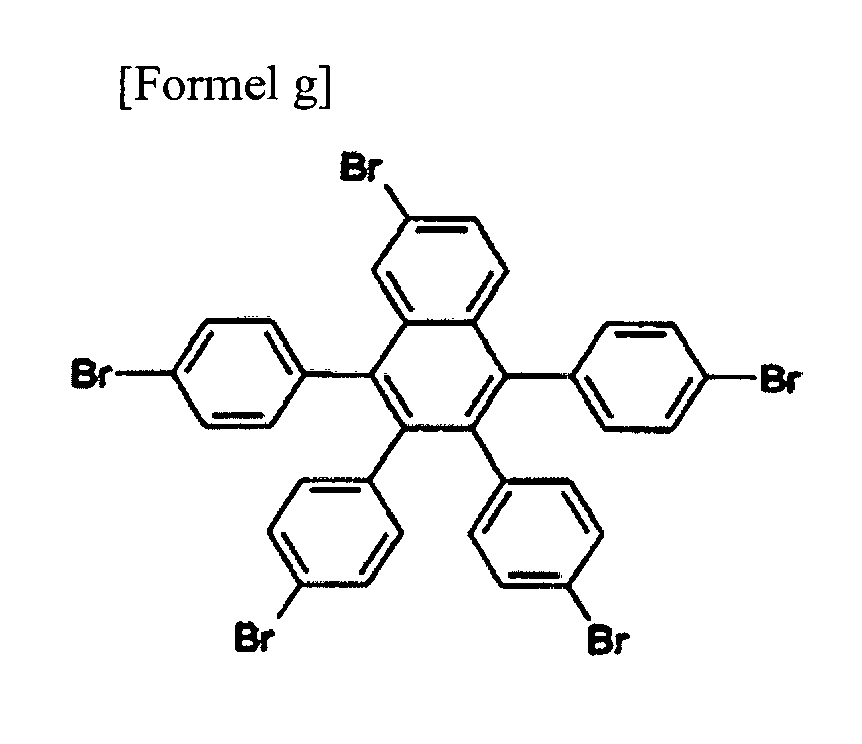
- Intermediate materials of Formulae a to g can be prepared using starting materials of Formulae h to k.
- the starting materials of Formulae h to k and isoamyl nitrite are dissolved in dichloroethane, and refluxed under stirring.
- Anthranylic acid or 2-amino 5-bromobenzoic acid dissolved in dichloroethane are added dropwise thereto to prepare intermediate materials of Formulae a to g.
- the intermediate materials are added to toluene with a precursor of substituent to be substituted to the compound of Formula 1, sodium t-butoxide, Pd(dba), and P(t-Bu), and are subject to reaction.
- the mixture is added to a mixed solution of THF and H O.
- the organic layer is separated from the mixture, dried and concentrated. The residue was purified by column chromatography and then re- crystallized from dichloromethane and ethanol to obtain a compound of Formula 1.
- the compound of Formula 1 is a novel structure of a retraphenylnaphthalene derivative, and can be used as various materials for an organic material layer in an organic light emitting device due to its structural properties. This will be described in detail, below.
- the steric core structure of the compound of Formula 1 for convenience of explanation, can be divided into three portions, A, B, and C, as shown in the following Formula.
- the compound of Formula 1 has the steric core structure in which a portion A, naphthalene bonds to portion B's, benzene rings with spiro bonding.
- the three-dimensional structure of the organic material minimizes pi-pi interaction in the organic materials, thereby formation of excited excimers and or excited exciplex is prevented.
- the conjugation length of the compound has a close relationship with an energy band gap.
- the energy band gap is reduced as the conjugation length of the compound increases.
- the conjugation length increases, even if the conjugated portions are not planar, the conjugations of the compound are reduced.
- the core structure since a conjugation structure between a portion A and a portion B is limited in the core structure of the compound of Formula 1, the core structure has a large energy band gap.
- substituent groups are introduced to R to R positions of the core structure having the large energy band gap so as to produce compounds having various energy band gaps.
- Substituent groups are introduced into portion B's, benzene rings, so as to easily produce compounds having a large energy band gap due to the above-described steric structure.
- Such structural properties of the compound of Formula 1 are advantageous in that the compound of Formula 1 can be applied to a phosphorescent or fluorescent blue host or dopant, an electron injecting or transporting material, a hole injecting or transporting material.
- substituent groups are introduced into a portion C, the portion C has less steric structure than the portion B. Therefore, if various substituent groups are introduced into a portion C, it is easy to make a band gap small, whereby the compound of Formula 1 can be advantageously applied to a green or red host or dopant.
- substituent groups are introduced to a portion B and a portion C in the compound of Formula 1 so as to produce compounds having various band gaps. Accordingly, substituent groups are introduced into the core structure of the compound of Formula 1 so as to produce substances capable of satisfying requirements of each organic layer, such as hole injecting or transporting layer, light emitting layer, and electron injecting or transporting layer in the organic light emitting device. Further, in the present invention, the compound having the proper energy level is selected depending on the substituent group among the compounds represented by Formula 1 to be used in the organic light emitting device, thereby it is possible to realize a device having a low drive voltage and a high optical efficiency.
- the present invention provides an organic electronic device comprising a first electrode, a second electrode, and organic material layers interposed therebetween, in which at least one layer of the organic material layers comprises the compound of Formula 1.
- the organic light emitting device according to the present invention can be prepared as a general structure by usual methods and materials known in the art, except that the compound of Formula 1 are used to form at least one organic material layer.
- the structures of the organic light emitting device according to the present invention are illustrated in Figs. 1 to 5 .
- the organic light emitting device can be prepared by depositing a metal, a metal oxide having conductivity or an alloy thereof on a substrate using a PVD (physical vapor deposition) process such as sputtering and e-beam evaporation to form an anode; forming an organic material layer comprising a hole injecting layer, a hole transporting layer, a light emitting layer, and an electron transporting layer on the anode; and depositing a material, which can be used as a cathode, thereon.
- PVD physical vapor deposition
- the organic light emitting device can be prepared by sequentially depositing a cathode material, an organic material layer, and an anode material on a substrate (see PCT Patent Application Publication WO 2003/012890 ).
- the organic material layer may be of a multilayer structure containing a hole injecting layer, a hole transporting layer, a light emitting layer, an electron transporting layer, and the like, but not limited thereto, and may be of a monolayer structure.
- the organic material layer can be produced to have a fewer number of layers, by using a variety of polymeric materials, by means of a solvent process rather than a deposit process, such as spin coating, dip coating, doctor blading, screen printing, ink jet printing, and heat transfer processes.
- the anode material is preferably a material having a large work function to facilitate hole injection usually to an organic material layer.
- Specific examples of the anode material which can be used in the present invention include metals such as vanadium, chromium, copper, zinc and gold, or an alloy thereof; metal oxides such as zinc oxide, indium oxide, indium-tin oxide (ITO), and indium zinc oxide (IZO); a combination of a metal and an oxide such as ZnO:Al and SnO :Sb; conductive polymers such as poly(3-methylthiophene), poly[3,4-(ethylene-1,2-dioxy)thiophene] (PEDT), polypyrrole and polyaniline.
- the cathode material is preferably a material having a small work function to facilitate electron injection usually to an organic material layer.
- Specific examples of the cathode material include metals such as magnesium, calcium, sodium, potassium, titanium, indium, yttrium, lithium, gadolinium, aluminum, silver, tin and lead, or an alloy thereof; multilayer structure materials such as LiF/ Al and LiO /Al.
- the hole injecting material is a material facilitating hole injection from an anode at low voltage.
- the HOMO (highest occupied molecular orbital) level of the hole injecting material is preferably located between the work function of the anode materials and the HOMO level of its neighboring organic material layer.
- Specific examples of the hole injecting material include organic materials of metal porphyrin, oligothiophene and arylamine series, organic materials of hexanitrile hexaazat- riphenylene and quinacridone series, organic materials of perylene series, and conductive polymers of anthraquinone, polyaniline, and polythiophene series.
- the hole transporting material is preferably a material having high hole mobility, which can transfer holes from the anode or the hole injecting layer toward the light emitting layer.
- Specific examples thereof include organic materials of arylamine series, conductive polymers and block copolymers having both conjugated portions and non- conjugated portions.
- the light emitting material are a material capable of emitting visible light by accepting and recombining holes from the hole transporting layer and electrons from the electron transporting layer, preferably a material having high quantum efficiency for fluorescence and phosphorescence.
- Specific examples thereof include 8 -hydroxy quinoline aluminum complex (AIq); compounds of carbazole series; dimerized styryl compounds; BAIq; 10-hydroxybenzoquinoline-metal compounds; compounds of benzoxazole, benzthiazole and benzimidazole series; polymers of poly(p-phenylenevinylene) (PPV) series; spiro compounds; and compounds of polyfluorene and rubrene series.
- AIq 8 -hydroxy quinoline aluminum complex
- compounds of carbazole series dimerized styryl compounds
- BAIq 10-hydroxybenzoquinoline-metal compounds
- compounds of benzoxazole, benzthiazole and benzimidazole series polymers of poly(p-phenylenevinylene) (PP
- the electron transporting material is suitably a material having high electron mobility, which can transfer electrons from the cathode to the light emitting layer.
- a material having high electron mobility which can transfer electrons from the cathode to the light emitting layer.
- Specific examples thereof include 8 -hydroxy quinoline aluminum complex (AIq); complexes including AIq ; organic radical compounds; and hydroxyflavone-metal complexes.
- the organic light emitting device according to the invention may be of a front-side, backside or double-sided light emission according to the materials used.
- a starting material represented by Formula i (2.0 g, 3.7 mmol) and isoamyl nitrite (0.54 mL, 4.1 mmol) were added to 50 ml, of dichloroe thane and heated to dissolve completely. While the mixture was refluxed under stirring, anthranylic acid (0.51 g, 3.7 mmol) completely dissolved in 25 mL of dichloroethane was slowly added dropwise thereto. After the color of the reaction mixture disappeared, the mixture was slowly cooled. The solvent was removed using a vacuum distillation system. The obtained solid was recrystallized from dichloromethane and ethanol to give a white solid powder.
- a starting material represented by Formula j (5.72 g, 10.5 mmol) and isoamyl nitrite (1.54 mL, 11.6 mmol) were added to 50 mL of dichloroethane and heated to dissolve completely. While the mixture was refluxed under stirring, anthranylic acid (1.44 g, 10.5 mmol) dissolved in 50 mL of dichloroethane was slowly added dropwise thereto. After the color of the reaction mixture disappeared, the mixture was slowly cooled. The solvent was removed using a vacuum distillation system. The obtained solid was recrystallized from dichloromethane and ethanol to give a white solid powder.
- a starting material represented by Formula k (3.50 g, 5 mmol) and isoamyl nitrite (0.73 mL, 11.6 mmol) were added to 50 mL of dichloroethane and heated to dissolve completely. While the mixture was refluxed under stirring, anthranylic acid (0.754 g, 5.5 mmol) dissolved in 50 mL of dichloroethane was slowly added drop wise thereto. After the color of the reaction mixture disappeared, the mixture was slowly cooled. The solvent was removed using a vacuum distillation system. The obtained solid was recrystallized from dichloromethane and ethanol to give a white solid powder.
- a starting material represented by Formula h (4.03 g, 10.5 mmol) and isoamyl nitrite (1.54 mL, 11.6 mmol) were added to 50 mL of dichloroethane and heated to dissolve completely. While the mixture was refluxed under stirring, 2-amino 5-bromobenzoic acid (2.27 g, 10.5 mmol) dissolved in 50 mL of dichloroethane was slowly added dropwise thereto. After the color of the reaction mixture disappeared, the mixture was slowly cooled. The solvent was removed using a vacuum distillation system. The obtained solid was recrystallized from dichloromethane and ethanol to give a white solid powder.
- a starting material represented by Formula i (6.4 g, 11.8 mmol) and isoamyl nitrite (1.73 mL, 13 mmol) were added to 300 mL of dichloroethane and heated to dissolve completely. While the mixture was refluxed under stirring, 2-amino-5-bromobenzoic acid (2.80 g, 13 mmol) dissolved in 100 mL of dichloroethane was slowly added dropwise thereto. After the color of the reaction mixture disappeared, the mixture was slowly cooled. The solvent was removed using a vacuum distillation system. The obtained solid was recrystallized from dichloromethane and ethanol to give a white solid powder.
- a starting material represented by Formula j (5.72 g, 10.5 mmol) and isoamyl nitrite (1.54 mL, 11.6 mmol) were added to 50 mL of dichloroethane and heated to dissolve completely. While the mixture was refluxed under stirring, 2-amino-5-bromobenzoic acid (2.27 g, 10.5 mmol) dissolved in 50 mL of dichloroethane was slowly added dropwise thereto. After the color of the reaction mixture disappeared, the mixture was slowly cooled. The solvent was removed using a vacuum distillation system. The obtained solid was recrystallized from dichloromethane and ethanol to give a white solid powder.
- the compound of Formula b (2.0 g, 3.4 mmol), carbazole (1.3 g, 7.8 mmol), sodium t-butoxide (0.81 g, 8.5 mmol), Pd(dba) (0.1 g, 0.2 mmol) and P(t-Bu) (0.04 g, 0.2 mmol) were added to toluene (40 mL), and then was refluxed under stirring for about 5 hours. After completing the reaction, the mixture was cooled to room temperature and added to a mixed solution of THF and H 2 O. The organic layer was separated from the mixture, dried over MgSO 4 and concentrated.
- the compound of Formula a (1.3 g, 2.2 mmol), naphthylphenylamine (1.1 g, 5.1 mmol), sodium t-butoxide (0.63 g, 6.6 mmol), Pd(dba) 2 (0.06 g, 0.1 mmol) and P(t-Bu) 3 (0.03 g, 0.1 mmol) were added to toluene (20 mL), and then the mixture was refluxed under stirring for about 2 hours. After completing the reaction, the mixture was cooled to room temperature and added to a mixed solution of THF and H 2 O. The organic layer was separated from the mixture, dried over MgSO 4 and concentrated.
- the compound of Formula a (1.3 g, 2.2 mmol), 3-tolylphenylamine (0.87 mL, 5.1 mmol), sodium t-butoxide (0.63 g, 6.6 mmol), Pd(dba) 2 (0.06 g, 0.1 mmol) and P(t-Bu) 3 (0.03 g, 0.1 mmol) were added to toluene (20 mL), and then was refluxed under stirring for about 2 hours. After completing the reaction, the mixture was cooled to room temperature and added to a mixed solution of THF and H O. The organic layer was separated from the mixture, dried over MgSO and concentrated.
- the compound of Formula d (1.06 g, 2.07 mmol), diphenylamine (0.39 g, 2.3 mmol), sodium t-butoxide(0.24 g, 2.5 mmol), Pd(dba) 2 (0.024 g, 0.04 mmol) and P(t - Bu) 3 (0.01 g, 0.04 mmol) were added to toluene (20 mL), and then was refluxed under stirring for about 1 hour. After completing the reaction, the mixture was cooled to room temperature and added to a mixed solution of THF and H 2 O. The organic layer was separated from the mixture, dried over MgSO 4 and concentrated.
- the compound of Formula e (0.51 g, 0.76 mmol), diphenylamine (0.41 g, 2.4 mmol), sodium t-butoxid (0.26 g, 2.7 mmol), Pd(dba) 2 (0.022 g, 0.04 mmol) and P(t - Bu) 4 (0.01 g, 0.04 mmol) were added to toluene (40 mL), and then was refluxed under stirring for about 12 hours. After completing the reaction, the mixture was cooled to room temperature and added to a mixed solution of THF and H 2 O. The organic layer was separated from the mixture, dried over MgSO 4 and concentrated.
- the compound of Formula a (0.50 g, 0.85 mmol), 4-phenylaminostilbene (0.48 g, 1.8 mmol), sodium t-butoxide(0.20 g, 2.1 mmol), Pd(dba) 2 (0.03 g, 0.05 mmol) and P(t- Bu) 3 (0.01 g, 0.05 mmol) were added to toluene (40 mL), and then was refluxed under stirring for about 1 hour. After completing the reaction, the mixture was cooled to room temperature and added to a mixed solution of THF and H 2 O. The organic layer was separated from the mixture, dried over MgSO 4 and concentrated.
- the compound of Formula b (0.50 g, 0.85 mmol), 4-phenylaminostilbene (0.48 g, 1.8 mmol), sodium t-butoxide (0.20 g, 2.1 mmol), Pd(dba) 2 (0.01 g, 0.02 mmol) and P(t-Bu) 3 (0.045 g, 0.02 mmol) were added to toluene (20 mL), and then was refluxed under stirring for about 3 hours. After completing the reaction, the mixture was cooled to room temperature and added to a mixed solution of THF and H 2 O. The organic layer was separated from the mixture, dried over MgSO 4 and concentrated.
- the compound of Formula d (0.49 g, 0.96 mmol), 4-phenylaminostilbene (0.28 g, 1.1 mmol), sodium t-butoxide (0.12 g, 2.9 mmol), Pd(dba) 2 (0.006 g, 0.01 mmol) and P(t-Bu) 3 (0.003 g, 0.01 mmol) were added to toluene (10 mL), and then was refluxed under stirring for about 2 hours. After completing the reaction, the mixture was cooled to room temperature and added to a mixed solution of THF and H 2 O. The organic layer was separated from the mixture, dried over MgSO 4 and concentrated.
- the compound of Formula e (0.50 g, 0.75 mmol), 4-phenylaminostilbene (0.63 g, 2.3 mmol), sodium t-butoxide (0.25 g, 2.6 mmol), Pd(dba) 2 (0.01 g, 0.015 mmol) and P(t-Bu) 3 (0.003 g, 0.015 mmol) were added to toluene (20 mL), and then was refluxed under stirring for about 3 hours. After completing the reaction, the mixture was cooled to room temperature and added to a mixed solution of THF and H 2 O. The organic layer was separated from the mixture, dried over MgSO 4 and concentrated.
- a glass substrate (Corning 7059 glass) on which a thin film of ITO (indium tin oxide) was coated to a thickness of 1000 A was immersed in distilled water having a detergent dissolved therein to wash the substrate with ultrasonic waves.
- the detergent as used herein was a product commercially available from Fisher Co. and the distilled water was one which had been twice filtered by using a filter commercially available from Millipore Co. ITO was washed for 30 minutes, and then washing with ultrasonic waves was repeated twice for 10 minutes by using distilled water. After the complexion of washing with distilled water, washing with ultrasonic waves was carried out by using solvents such as isopropyl alcohol, acetone and methanol. The resultant product was dried.
- hexanitrile hexaazatriphenylene 500 ⁇
- 4,4'-bis[N-(1-naphthyl)-N-phenyl amino] biphenyl 400 ⁇
- AIq 3 300 A
- the compound (200 ⁇ ) of the following Formula 5-1 prepared in Preparative Example 14 were sequentially coated by thermal vacuum deposition to form a hole injecting layer, a hole transporting layer, a light emitting layer, and an electron transporting layer, respectively.
- Lithium fluoride (LiF) and aluminum were sequentially deposited on the electron transporting layer to thicknesses of 12 A and 2000 ⁇ respectively, to form a cathode, thereby obtaining an organic light emitting device.
- the deposition rate of the organic material was maintained at 0.4 to 0.7 ⁇ /sec and the deposition rate of lithium fluoride on the cathode was maintained at 0.3 ⁇ /sec and the deposition rate of aluminum was maintained at 2 ⁇ /sec.
- the degree of vacuum upon deposition was maintained at 2 x 10 -7 to 5 x 10 -8 torr.
- the compound (800 ⁇ ) of the following Formula A, 4,4'-bis[N-(1-naphthyl)-N-phenylamino]biphenyl (NPB) (400 ⁇ ), the compound (300 ⁇ ) of the following Formula 6-1 prepared in Preparative Example 16, and the compound (200 ⁇ ) of the following Formula B were sequentially coated by thermal vacuum deposition to form a hole injecting layer, a hole transporting layer, a light emitting layer, and an electron transporting layer, respectively.
- Lithium fluoride (LiF) and aluminum were sequentially deposited on the electron transporting layer (the compound of Formula B) to thicknesses of 12 ⁇ and 2000 ⁇ respectively, to form a cathode, thereby obtaining an organic light emitting device.
- the deposition rate of the organic material was maintained at 0.4 to 0.7 ⁇ /sec and the deposition rate of lithium fluoride on the cathode was maintained at 0.3 ⁇ /sec and the deposition rate of aluminum was maintained at 2 ⁇ / sec.
- the degree of vacuum upon deposition was maintained at 2 x 10 -7 to 5 x 10 -8 torr.
- An organic light emitting device was prepared in the same manner as in Experimental Example 2, except that the compound or Formula 6-2 prepared in Preparative Example 17 was used instead of the compound of Formula 6-1.
- a forward electric field of 8.1 V was applied to the organic light emitting device as prepared above, blue light emission of 1700 cd/m 2 (nit) was observed.
- An organic light emitting device was prepared in the same manner as in Experimental Example 2, except that 2% by weight of the compound of following Formula C was added to the compound of Formula 6- 1 upon forming a light emitting layer.
- a forward electric field of 8.1 V was applied to the organic light emitting device as prepared above, blue light emission of 3700 cd/m 2 (nit) was observed.
Landscapes
- Chemical & Material Sciences (AREA)
- Organic Chemistry (AREA)
- Engineering & Computer Science (AREA)
- Materials Engineering (AREA)
- Physics & Mathematics (AREA)
- Spectroscopy & Molecular Physics (AREA)
- Inorganic Chemistry (AREA)
- Electroluminescent Light Sources (AREA)
- Organic Low-Molecular-Weight Compounds And Preparation Thereof (AREA)
- Indole Compounds (AREA)
- Low-Molecular Organic Synthesis Reactions Using Catalysts (AREA)
Claims (6)
- Verbindung der folgenden Formel 1:

- Verbindung nach Anspruch 1, wobei die Verbindung der Formel 1 ausgewählt ist aus den folgenden Verbindungen der Formeln 11 bis 17:

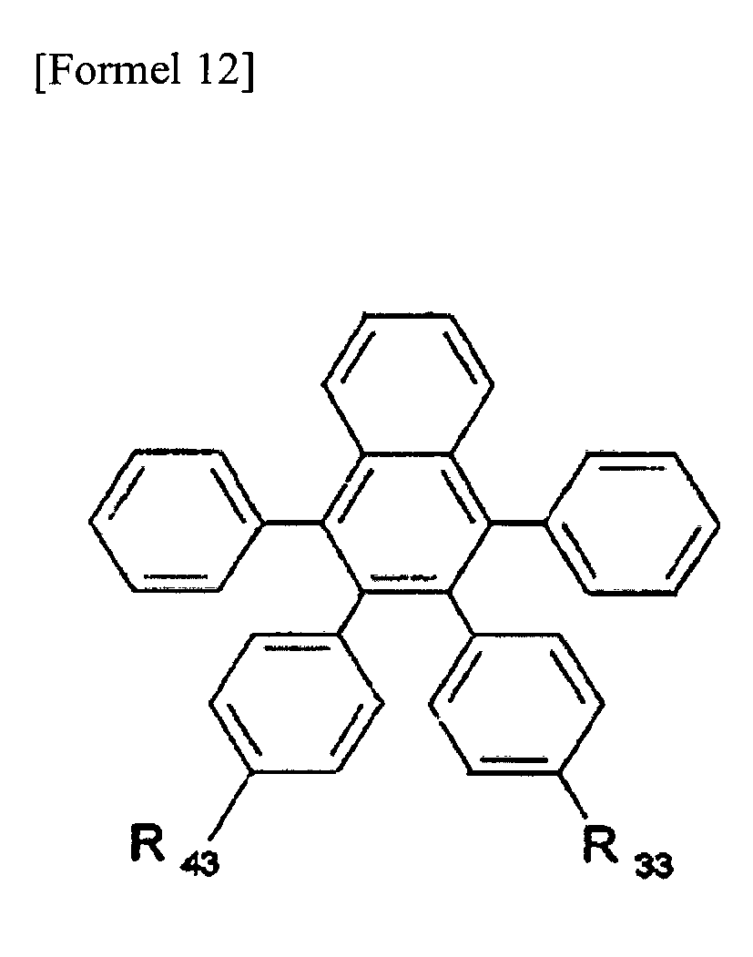


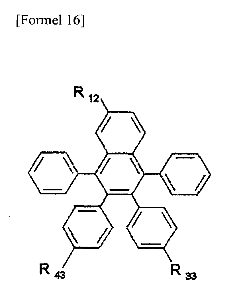

- Verbindung nach Anspruch 1, wobei die Verbindung der Formel 1 ausgewählt ist aus Verbindungen, die durch die folgende Formel dargestellt sind:


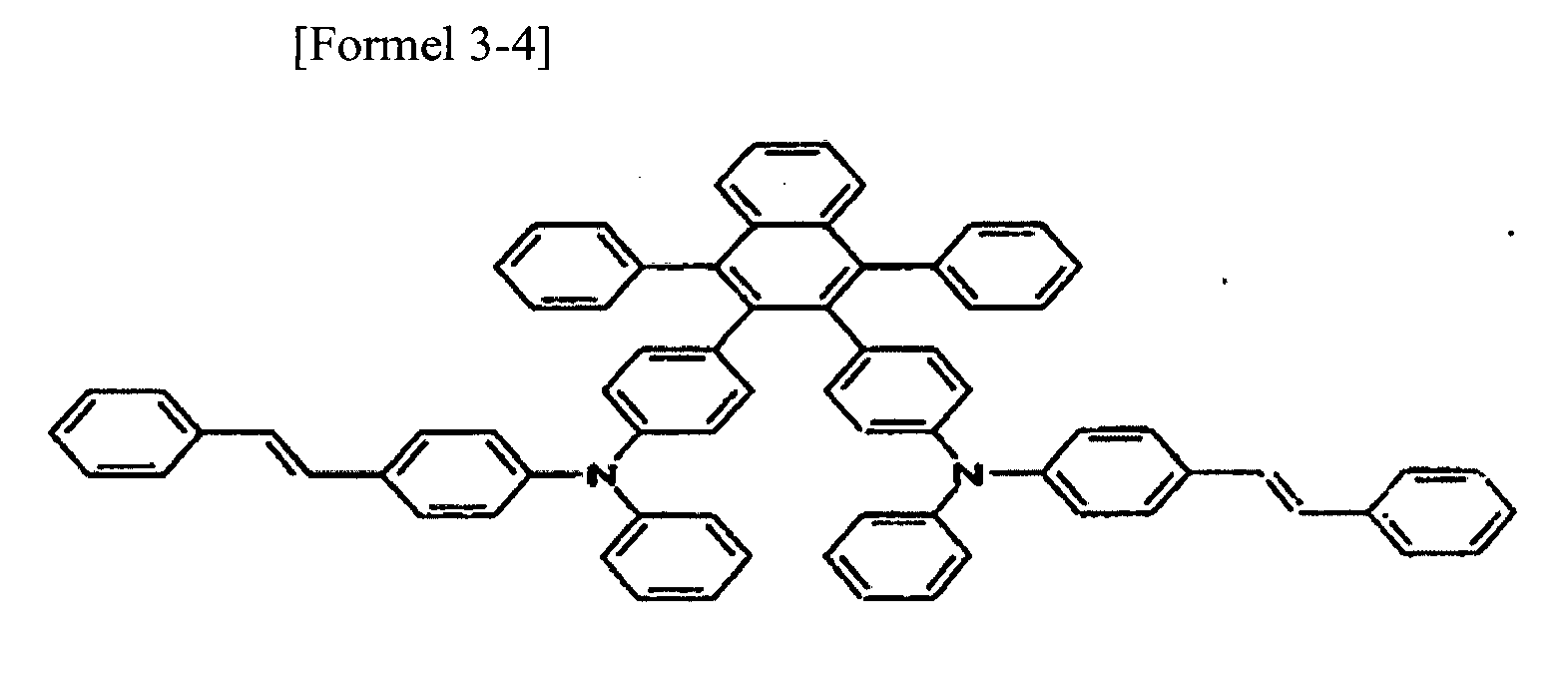


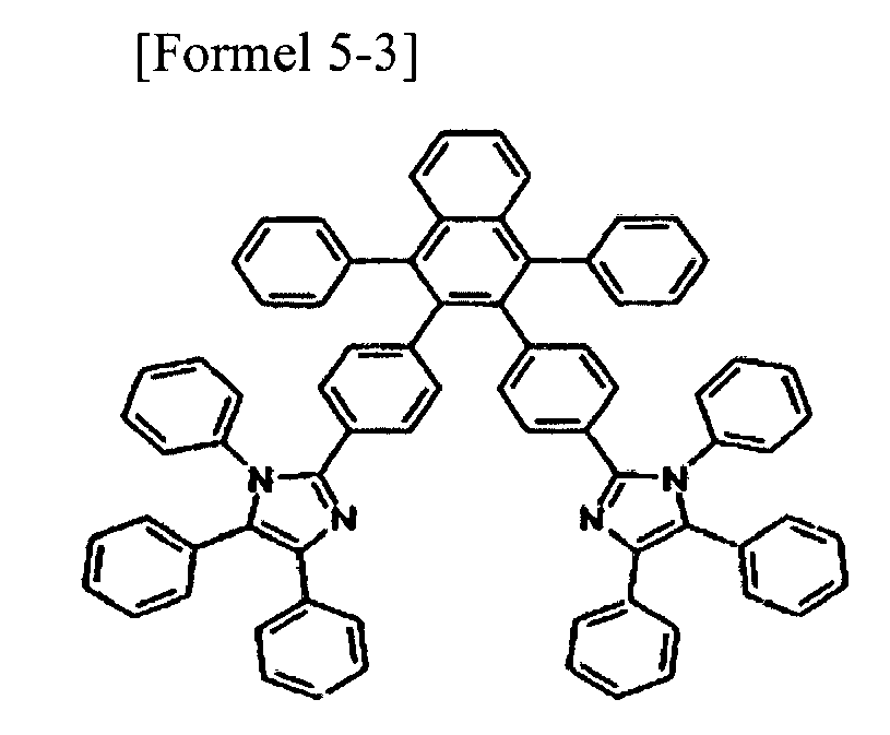


- Verfahren zum Herstellen der Verbindung von Formel 1 nach Anspruch 1, umfassend die Schritte:a) Auflösen wenigstens eines der Ausgangsmaterialien der Formeln h bis k und von Isoamylnitrit in Dichlorethan, Rühren unter Rückfluss und Zufügen von Anthranilsäure oder 2-Amino-5-brombenzoesäure, gelöst in Dichlorethan, um wenigstens eines der Zwischenmaterialien der Formeln a bis g herzustellen; undb) Umsetzen des Zwischenmaterials mit einer Vorstufe eines Substituenten, der in das Zwischenmaterial eingefügt werden soll, Natrium-t-butoxid, Pd(dba)2 und P(t-Bu) in Toluol, Zufügen der Mischung zu einer gemischten Lösung aus THF und H2O, Abtrennen einer organischen Schicht, Trocknen und Konzentrieren des Rückstands und Umkristallisieren aus Dichlormethan und Ethanol.




- Organische lichtemittierende Vorrichtung umfassend eine erste Elektrode, wenigstens eine organische Materialschicht und eine zweite Elektrode, sequentiell gestapelt, wobei die wenigstens eine organische Materialschicht die Verbindung nach Anspruch 1 umfasst.
- Organische lichtemittierende Vorrichtung nach Anspruch 5, wobei die organische Materialschicht wenigstens eine Schicht umfasst, die ausgewählt ist aus den Gruppen bestehend aus einer Lochinjektionsschicht, einer Lochtransportschicht, einer lichtemittierenden Schicht, einer Elektronentransportschicht und einer Elektroneninjektionsschicht.
Applications Claiming Priority (2)
| Application Number | Priority Date | Filing Date | Title |
|---|---|---|---|
| KR20060022845 | 2006-03-10 | ||
| PCT/KR2007/001174 WO2007105884A1 (en) | 2006-03-10 | 2007-03-09 | Tetraphenylnaphthalene derivatives and organic light emitting diode using the same |
Publications (3)
| Publication Number | Publication Date |
|---|---|
| EP1993992A1 EP1993992A1 (de) | 2008-11-26 |
| EP1993992A4 EP1993992A4 (de) | 2010-10-27 |
| EP1993992B1 true EP1993992B1 (de) | 2014-11-26 |
Family
ID=38509675
Family Applications (1)
| Application Number | Title | Priority Date | Filing Date |
|---|---|---|---|
| EP07715570.3A Active EP1993992B1 (de) | 2006-03-10 | 2007-03-09 | Tetraphenylnaphthalinderivate und organische lichtemittierende diode, bei der diese verwendet werden |
Country Status (7)
| Country | Link |
|---|---|
| US (1) | US8329316B2 (de) |
| EP (1) | EP1993992B1 (de) |
| JP (2) | JP5437641B2 (de) |
| KR (1) | KR100852326B1 (de) |
| CN (1) | CN101400643B (de) |
| TW (1) | TWI359803B (de) |
| WO (1) | WO2007105884A1 (de) |
Families Citing this family (21)
| Publication number | Priority date | Publication date | Assignee | Title |
|---|---|---|---|---|
| TWI359803B (en) * | 2006-03-10 | 2012-03-11 | Lg Chemical Ltd | Tetraphenylnaphthalene derivatives and organic lig |
| KR100893044B1 (ko) * | 2006-07-26 | 2009-04-15 | 주식회사 엘지화학 | 안트라센 유도체, 이를 이용한 유기 전자 소자 및 이 유기전자 소자를 포함하는 전자 장치 |
| CN101679205A (zh) * | 2007-06-01 | 2010-03-24 | E.I.内穆尔杜邦公司 | 空穴传输材料 |
| WO2008152939A1 (ja) * | 2007-06-15 | 2008-12-18 | Idemitsu Kosan Co., Ltd. | 芳香族ホウ素誘導体、有機エレクトロルミネッセンス素子及びそれを用いた有機エレクトロルミネッセンス材料含有溶液 |
| US9309174B2 (en) | 2007-06-20 | 2016-04-12 | Idemitsu Kosan Co., Ltd. | Polycyclic ring assembly compound and organic electroluminescent device employing the same |
| KR100991416B1 (ko) * | 2007-12-31 | 2010-11-03 | 다우어드밴스드디스플레이머티리얼 유한회사 | 유기 발광 화합물 및 이를 포함하는 유기 발광 소자 |
| TW200948929A (en) * | 2008-02-22 | 2009-12-01 | Toyo Ink Mfg Co | Material for organic electro-luminescence element and organic electro-luminescence element |
| KR100901887B1 (ko) * | 2008-03-14 | 2009-06-09 | (주)그라쎌 | 신규한 유기 발광 화합물 및 이를 채용하고 있는 유기 발광소자 |
| JP2012510540A (ja) | 2008-12-01 | 2012-05-10 | イー・アイ・デュポン・ドウ・ヌムール・アンド・カンパニー | 電気活性材料 |
| IT1403886B1 (it) | 2010-12-15 | 2013-11-08 | Sigea Srl | Uso di esteri lipoati di glicosamminoglicani in campo tricologico |
| KR101499356B1 (ko) | 2013-06-28 | 2015-03-05 | 주식회사 엘지화학 | 헤테로환 화합물 및 이를 포함하는 유기 발광 소자 |
| KR101672096B1 (ko) | 2013-09-30 | 2016-11-02 | 주식회사 엘지화학 | 헤테로환 화합물 및 이를 포함하는 유기 발광 소자 |
| JP6194121B2 (ja) | 2013-09-30 | 2017-09-06 | エルジー・ケム・リミテッド | 複素環化合物及びこれを用いた有機発光素子 |
| KR102285608B1 (ko) * | 2015-03-23 | 2021-08-04 | 덕산네오룩스 주식회사 | 유기전기 소자용 화합물, 이를 이용한 유기전기소자 및 그 전자 장치 |
| CN107383071A (zh) * | 2017-07-28 | 2017-11-24 | 长春海谱润斯科技有限公司 | 一种咪唑类衍生物及其应用 |
| KR20190052505A (ko) * | 2017-11-08 | 2019-05-16 | 에스에프씨 주식회사 | 아민 치환기를 갖는 나프탈렌 유도체 화합물 및 이를 포함하는 유기발광소자 |
| KR102790454B1 (ko) * | 2018-01-25 | 2025-04-08 | 듀폰스페셜티머터리얼스코리아 유한회사 | 유기 전계 발광 화합물 및 이를 포함하는 유기 전계 발광 소자 |
| KR102730992B1 (ko) * | 2018-10-12 | 2024-11-20 | 삼성디스플레이 주식회사 | 유기 전계 발광 소자 및 유기 전계 발광 소자용 아민 화합물 |
| EP3828161B1 (de) | 2019-11-27 | 2026-04-08 | Samsung Display Co., Ltd. | Organische elektrolumineszenzvorrichtung und diaminverbindung für die organische elektrolumineszenzvorrichtung |
| KR102868887B1 (ko) * | 2019-11-27 | 2025-10-13 | 삼성디스플레이 주식회사 | 유기 전계 발광 소자 및 유기 전계 발광 소자용 디아민 화합물 |
| KR102886634B1 (ko) * | 2020-07-24 | 2025-11-13 | 주식회사 엘지화학 | 신규한 화합물 및 이를 이용한 유기 발광 소자 |
Family Cites Families (12)
| Publication number | Priority date | Publication date | Assignee | Title |
|---|---|---|---|---|
| US5077142A (en) * | 1989-04-20 | 1991-12-31 | Ricoh Company, Ltd. | Electroluminescent devices |
| US5989737A (en) * | 1997-02-27 | 1999-11-23 | Xerox Corporation | Organic electroluminescent devices |
| JP3965800B2 (ja) * | 1997-12-01 | 2007-08-29 | チッソ株式会社 | トリアリールアミン誘導体を用いた有機電界発光素子 |
| AU2002317506A1 (en) * | 2001-07-11 | 2003-01-29 | Fuji Photo Film Co., Ltd. | Light-emitting device and aromatic compound |
| JP4003824B2 (ja) * | 2001-07-11 | 2007-11-07 | 富士フイルム株式会社 | 発光素子 |
| JP4074529B2 (ja) * | 2003-02-25 | 2008-04-09 | 独立行政法人科学技術振興機構 | 全置換ナフタレン誘導体の製造方法 |
| EP1491568A1 (de) * | 2003-06-23 | 2004-12-29 | Covion Organic Semiconductors GmbH | Halbleitende Polymere |
| US20050025993A1 (en) * | 2003-07-25 | 2005-02-03 | Thompson Mark E. | Materials and structures for enhancing the performance of organic light emitting devices |
| US7018723B2 (en) * | 2003-07-25 | 2006-03-28 | The University Of Southern California | Materials and structures for enhancing the performance of organic light emitting devices |
| JP2005302657A (ja) | 2004-04-15 | 2005-10-27 | Sharp Corp | 有機発光素子 |
| KR101192519B1 (ko) * | 2004-05-12 | 2012-10-17 | 이데미쓰 고산 가부시키가이샤 | 방향족 아민 유도체, 이를 이용한 유기 전기 발광 소자 및방향족 아민 유도체의 제조방법 |
| TWI359803B (en) * | 2006-03-10 | 2012-03-11 | Lg Chemical Ltd | Tetraphenylnaphthalene derivatives and organic lig |
-
2007
- 2007-03-08 TW TW096108056A patent/TWI359803B/zh active
- 2007-03-09 JP JP2008558210A patent/JP5437641B2/ja active Active
- 2007-03-09 EP EP07715570.3A patent/EP1993992B1/de active Active
- 2007-03-09 KR KR1020070023452A patent/KR100852326B1/ko active Active
- 2007-03-09 CN CN2007800085671A patent/CN101400643B/zh active Active
- 2007-03-09 US US12/224,877 patent/US8329316B2/en active Active
- 2007-03-09 WO PCT/KR2007/001174 patent/WO2007105884A1/en not_active Ceased
-
2012
- 2012-10-05 JP JP2012223095A patent/JP2013053151A/ja active Pending
Also Published As
| Publication number | Publication date |
|---|---|
| JP2009529526A (ja) | 2009-08-20 |
| EP1993992A1 (de) | 2008-11-26 |
| WO2007105884A1 (en) | 2007-09-20 |
| CN101400643B (zh) | 2013-03-27 |
| CN101400643A (zh) | 2009-04-01 |
| TW200740716A (en) | 2007-11-01 |
| US20090174312A1 (en) | 2009-07-09 |
| EP1993992A4 (de) | 2010-10-27 |
| KR100852326B1 (ko) | 2008-08-14 |
| JP5437641B2 (ja) | 2014-03-12 |
| TWI359803B (en) | 2012-03-11 |
| JP2013053151A (ja) | 2013-03-21 |
| KR20070092667A (ko) | 2007-09-13 |
| US8329316B2 (en) | 2012-12-11 |
Similar Documents
| Publication | Publication Date | Title |
|---|---|---|
| EP1993992B1 (de) | Tetraphenylnaphthalinderivate und organische lichtemittierende diode, bei der diese verwendet werden | |
| JP4842319B2 (ja) | 新規なアントラセン誘導体、その製造方法、およびこれを用いた有機電気発光素子 | |
| KR101460361B1 (ko) | 새로운 이미다졸 유도체 및 이를 이용한 유기전자소자 | |
| JP5638612B2 (ja) | 新規な複素環誘導体およびこれを用いた有機発光素子 | |
| JP5253378B2 (ja) | 新規なアントラセン誘導体、その製造方法、およびそれを用いた有機電子素子 | |
| JP5373769B2 (ja) | 新規のジアミン誘導体およびこれを用いた有機電子素子 | |
| KR20090114008A (ko) | 신규한 이미다졸 유도체 및 이를 이용한 유기전자소자 | |
| KR20100007143A (ko) | 신규한 안트라센 유도체 및 이를 이용한 유기전자소자 | |
| KR100967355B1 (ko) | 유기 전기 발광 소자용 재료 및 이를 이용한 유기 전기발광 소자 | |
| KR101396647B1 (ko) | 신규한 안트라센 유도체, 이의 제조방법 및 이를 이용한 유기전자소자 | |
| KR101153095B1 (ko) | 신규한 시클로알켄 유도체 및 이를 이용한 유기전자소자 | |
| US7385095B2 (en) | Indene derivatives and organic light emitting diode using the same | |
| KR101295492B1 (ko) | 신규한 안트라센 유도체 및 이를 이용한 유기전기소자 | |
| KR20110131155A (ko) | 신규한 디티에노피롤 유도체 및 이를 이용한 유기전기소자 | |
| KR101182560B1 (ko) | 신규한 디티에노피롤 유도체 및 이를 이용한 유기전기소자 | |
| KR20140016214A (ko) | 신규한 안트라센 유도체, 이의 제조방법 및 이를 이용한 유기전자소자 |
Legal Events
| Date | Code | Title | Description |
|---|---|---|---|
| PUAI | Public reference made under article 153(3) epc to a published international application that has entered the european phase |
Free format text: ORIGINAL CODE: 0009012 |
|
| 17P | Request for examination filed |
Effective date: 20080829 |
|
| AK | Designated contracting states |
Kind code of ref document: A1 Designated state(s): DE FR GB |
|
| RIN1 | Information on inventor provided before grant (corrected) |
Inventor name: LEE, DONG-HOON Inventor name: JEONG, DONG-SEOB Inventor name: JANG, HYE-YOUNG Inventor name: KIM, KONG-KYEOM Inventor name: HONG, SUNG-KIL Inventor name: KIM, YEON-HWAN |
|
| RBV | Designated contracting states (corrected) |
Designated state(s): DE FR GB |
|
| A4 | Supplementary search report drawn up and despatched |
Effective date: 20100929 |
|
| 17Q | First examination report despatched |
Effective date: 20120427 |
|
| DAX | Request for extension of the european patent (deleted) | ||
| GRAP | Despatch of communication of intention to grant a patent |
Free format text: ORIGINAL CODE: EPIDOSNIGR1 |
|
| RIC1 | Information provided on ipc code assigned before grant |
Ipc: C07C 211/58 20060101ALI20140814BHEP Ipc: C07C 211/54 20060101AFI20140814BHEP Ipc: H01L 51/50 20060101ALI20140814BHEP Ipc: H01L 51/00 20060101ALI20140814BHEP |
|
| INTG | Intention to grant announced |
Effective date: 20140911 |
|
| GRAS | Grant fee paid |
Free format text: ORIGINAL CODE: EPIDOSNIGR3 |
|
| GRAA | (expected) grant |
Free format text: ORIGINAL CODE: 0009210 |
|
| AK | Designated contracting states |
Kind code of ref document: B1 Designated state(s): DE FR GB |
|
| REG | Reference to a national code |
Ref country code: GB Ref legal event code: FG4D |
|
| REG | Reference to a national code |
Ref country code: DE Ref legal event code: R096 Ref document number: 602007039416 Country of ref document: DE Effective date: 20150108 |
|
| REG | Reference to a national code |
Ref country code: DE Ref legal event code: R097 Ref document number: 602007039416 Country of ref document: DE |
|
| PLBE | No opposition filed within time limit |
Free format text: ORIGINAL CODE: 0009261 |
|
| STAA | Information on the status of an ep patent application or granted ep patent |
Free format text: STATUS: NO OPPOSITION FILED WITHIN TIME LIMIT |
|
| 26N | No opposition filed |
Effective date: 20150827 |
|
| REG | Reference to a national code |
Ref country code: FR Ref legal event code: PLFP Year of fee payment: 10 |
|
| REG | Reference to a national code |
Ref country code: FR Ref legal event code: PLFP Year of fee payment: 11 |
|
| REG | Reference to a national code |
Ref country code: FR Ref legal event code: PLFP Year of fee payment: 12 |
|
| PGFP | Annual fee paid to national office [announced via postgrant information from national office to epo] |
Ref country code: DE Payment date: 20250220 Year of fee payment: 19 |
|
| PGFP | Annual fee paid to national office [announced via postgrant information from national office to epo] |
Ref country code: FR Payment date: 20250221 Year of fee payment: 19 |
|
| PGFP | Annual fee paid to national office [announced via postgrant information from national office to epo] |
Ref country code: GB Payment date: 20250224 Year of fee payment: 19 |