EP1994255B1 - Generation d'impulsions sismiques dans un trou de sonde a l'aide d'une vanne a ouverture rapide - Google Patents
Generation d'impulsions sismiques dans un trou de sonde a l'aide d'une vanne a ouverture rapide Download PDFInfo
- Publication number
- EP1994255B1 EP1994255B1 EP06824978.8A EP06824978A EP1994255B1 EP 1994255 B1 EP1994255 B1 EP 1994255B1 EP 06824978 A EP06824978 A EP 06824978A EP 1994255 B1 EP1994255 B1 EP 1994255B1
- Authority
- EP
- European Patent Office
- Prior art keywords
- valve
- gap
- seal
- area
- borehole
- Prior art date
- Legal status (The legal status is an assumption and is not a legal conclusion. Google has not performed a legal analysis and makes no representation as to the accuracy of the status listed.)
- Active
Links
- 239000007788 liquid Substances 0.000 claims description 83
- 238000007789 sealing Methods 0.000 claims description 6
- 230000004323 axial length Effects 0.000 claims description 5
- 238000011144 upstream manufacturing Methods 0.000 claims description 5
- 238000000034 method Methods 0.000 claims description 3
- 230000000644 propagated effect Effects 0.000 claims 1
- 230000015572 biosynthetic process Effects 0.000 description 15
- 229920006395 saturated elastomer Polymers 0.000 description 11
- 230000001351 cycling effect Effects 0.000 description 7
- IJGRMHOSHXDMSA-UHFFFAOYSA-N Atomic nitrogen Chemical compound N#N IJGRMHOSHXDMSA-UHFFFAOYSA-N 0.000 description 6
- 230000008901 benefit Effects 0.000 description 6
- 230000001427 coherent effect Effects 0.000 description 6
- 230000000694 effects Effects 0.000 description 5
- 239000002184 metal Substances 0.000 description 5
- 229910052751 metal Inorganic materials 0.000 description 5
- 238000004519 manufacturing process Methods 0.000 description 4
- 238000002347 injection Methods 0.000 description 3
- 239000007924 injection Substances 0.000 description 3
- 239000000463 material Substances 0.000 description 3
- 229910052757 nitrogen Inorganic materials 0.000 description 3
- 230000002035 prolonged effect Effects 0.000 description 3
- XEEYBQQBJWHFJM-UHFFFAOYSA-N Iron Chemical compound [Fe] XEEYBQQBJWHFJM-UHFFFAOYSA-N 0.000 description 2
- 230000008859 change Effects 0.000 description 2
- 238000005516 engineering process Methods 0.000 description 2
- 239000002783 friction material Substances 0.000 description 2
- 230000014509 gene expression Effects 0.000 description 2
- 239000000696 magnetic material Substances 0.000 description 2
- 230000009467 reduction Effects 0.000 description 2
- 230000002829 reductive effect Effects 0.000 description 2
- 239000011435 rock Substances 0.000 description 2
- 230000035939 shock Effects 0.000 description 2
- 229910001220 stainless steel Inorganic materials 0.000 description 2
- 239000010935 stainless steel Substances 0.000 description 2
- 230000001960 triggered effect Effects 0.000 description 2
- XLYOFNOQVPJJNP-UHFFFAOYSA-N water Substances O XLYOFNOQVPJJNP-UHFFFAOYSA-N 0.000 description 2
- 241000169624 Casearia sylvestris Species 0.000 description 1
- 208000031481 Pathologic Constriction Diseases 0.000 description 1
- 239000006096 absorbing agent Substances 0.000 description 1
- 230000001133 acceleration Effects 0.000 description 1
- 230000002238 attenuated effect Effects 0.000 description 1
- 238000004364 calculation method Methods 0.000 description 1
- 230000001010 compromised effect Effects 0.000 description 1
- 238000010276 construction Methods 0.000 description 1
- 230000036461 convulsion Effects 0.000 description 1
- 125000004122 cyclic group Chemical group 0.000 description 1
- 230000005611 electricity Effects 0.000 description 1
- 230000002401 inhibitory effect Effects 0.000 description 1
- 230000002452 interceptive effect Effects 0.000 description 1
- 229910052742 iron Inorganic materials 0.000 description 1
- 238000011089 mechanical engineering Methods 0.000 description 1
- 239000003129 oil well Substances 0.000 description 1
- 230000036961 partial effect Effects 0.000 description 1
- 239000004810 polytetrafluoroethylene Substances 0.000 description 1
- 229920001343 polytetrafluoroethylene Polymers 0.000 description 1
- 239000011148 porous material Substances 0.000 description 1
- 230000000750 progressive effect Effects 0.000 description 1
- 230000003068 static effect Effects 0.000 description 1
- 230000000638 stimulation Effects 0.000 description 1
- 230000002459 sustained effect Effects 0.000 description 1
Images


Classifications
-
- E—FIXED CONSTRUCTIONS
- E21—EARTH OR ROCK DRILLING; MINING
- E21B—EARTH OR ROCK DRILLING; OBTAINING OIL, GAS, WATER, SOLUBLE OR MELTABLE MATERIALS OR A SLURRY OF MINERALS FROM WELLS
- E21B43/00—Methods or apparatus for obtaining oil, gas, water, soluble or meltable materials or a slurry of minerals from wells
- E21B43/003—Vibrating earth formations
-
- E—FIXED CONSTRUCTIONS
- E21—EARTH OR ROCK DRILLING; MINING
- E21B—EARTH OR ROCK DRILLING; OBTAINING OIL, GAS, WATER, SOLUBLE OR MELTABLE MATERIALS OR A SLURRY OF MINERALS FROM WELLS
- E21B28/00—Vibration generating arrangements for boreholes or wells, e.g. for stimulating production
-
- G—PHYSICS
- G01—MEASURING; TESTING
- G01V—GEOPHYSICS; GRAVITATIONAL MEASUREMENTS; DETECTING MASSES OR OBJECTS; TAGS
- G01V1/00—Seismology; Seismic or acoustic prospecting or detecting
- G01V1/02—Generating seismic energy
- G01V1/133—Generating seismic energy using fluidic driving means, e.g. highly pressurised fluids; using implosion
Definitions
- the technology described herein relates to boreholes In the ground, and to injecting pressurised liquid very rapidly out from the borehole into the surrounding ground formation.
- surge-pulsing (as described in that publication) can be very effective in homogenising the ground around a borehole, and thus maximising the ground's conductivity.
- a large charge-volume e.g. several litres
- the liquid/ground homogenising effect can be radiated large distances (e.g scores of metres) away from the borehole during a surge-pulsing operation.
- a high-energy seismic-pressure pulse can cause the porosity of the ground to increase momentarily. That is to say, at a particular point in the ground formation, as the seismic waves approach and pass, the sudden increase in pressure lifts the ground slightly, at that point. If the ground has a porosity of, say, thirty percent, the passing wave can increase the porosity of the ground in the order of as much as a tenth of a percent.
- the seismic (pressure) wave can thus also be regarded as a porosity wave. As pressure increases, so conductivity increases, with the result that a larger charge-volume of liquid can be injected greater distances into the ground, per pulse. The above is not intended as a complete and accurate account of how/why adding a seismic component can enhance bulk-volumetric pulses: suffice it to say that in many instances that is what happens.
- US 5 836 393 relates to oil well production, particularly to a method and apparatus for downhole stimulation of oil production from a well by generating cyclic shock waves in and around the wellbore according to claims 1 and 15.
- Another aim is to provide an apparatus that can provide such injection of liquid on a continuous cycling basis. Cycle rates will vary within the range, typically, from three cycles per second to two cycles per minute. Typically, the kind of cycling which benefits from introducing a seismic component to the cycle is continued for a few hours or a few days (and for much longer in some cases).
- cycling having a seismic component is usually only carried out when the ground is already fully saturated with liquid, and indeed over-saturated, and the in-ground liquid is at a substantial pressure. Furthermore, the in-ground liquid around the borehole should have been transformed (e.g by a period of surge-pulsing) into a coherent body.
- the benefit of introducing the seismic component into the surge-pulses, at such time, is that the extent of the coherent body can be engineered to extend a few (or several) more metres radius away from the borehole. Furthermore, it may be expected that as the body becomes more coherent, so "fingering" of the injected liquid tends to be reduced, in that the ground between the fingers gradually, in turn, becomes saturated with liquid.
- liquid is simply injected into the ground under a static pressure. Then, once the ground has become saturated, the technicians commence surge-pulsing, the effect of which is that, even though the ground is already saturated, large extra volumes of liquid can be injected into the ground. Gradually, the coherent body of liquid is created, around the borehole, which surges out and back, as a body, every cycle.
- the seismic surge-pulsing might comprise, say, 100,000 cycles In a typical application.
- the number of cycles of course varies a great deal from site to site, but it will be understood that there is a heavy requirement for the apparatus to be engineered for a prolonged service life.
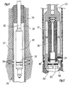
- pressurised liquid is fed into the apparatus from above, and occupies the chamber 23.
- the slider 24 is down, as shown in Fig 1 , the liquid passes out from the Interior chamber 23, through the gap 25.
- the injector apparatus of Figs 1-3 is used in the manner indicated in Fig 4 .
- a borehole 26 has been made in the ground, and the borehole is lined with a well-casing 27.
- Perforations 28 have been made in the well-casing 27 at a pre-determined depth. The intent is to inject water or other liquid into the surrounding ground formation, at the desired depth, out through the perforations 28.
- an inflatable packer 29 is positioned above the injector apparatus, which seals off the annular space 30 between the well-casing 27 and the rod 32 upon which the injector 20 is supported.
- the rod 32 is hollow, and serves to convey liquid down from a reservoir at the surface to the injector assembly.
- a pump and other facilities are provided at the surface.
- the injector apparatus includes the valve member or slider 24.
- the slider When the slider is in the UP position (as in Fig 4 ), the (male) conical sealing face 34 of the slider 24 engages the (female) conical seat face 35 of the body 36.
- the slider 24 When the slider 24 is in the DOWN position ( Fig 1 ), liquid can flow out through the open gap 25, into the annular space 30, and thence out through the perforations 28 into the ground formation around the borehole.
- the gap 25 is full-open, i.e the slider 24 is DOWN, while liquid is pumped from the surface down into the borehole, and out into the formation. This continues until the ground around the borehole is saturated.
- the solenoids 37,38 would not normally be operated during this preliminary phase.
- the slider 24 adopts the DOWN position when neither solenoid is energised.
- one of the desired effects of surge-pulsing is to make the ground more saturated. This may be explained as follows. When the ground is simply pressurised, a point is reached at which no further liquid can be forced into the ground at a given applied pressure (more liquid can be forced into the ground if the steady pressure is increased, of course). After surge-pulsing has been carried out, now more (often, a lot more) liquid can be forced into the ground at the applied pressure. Surge-pulsing effectively increases the sizes of the pore spaces.
- the saturation that arises from a steady applied pressure may be termed staticsaturation, and the greater saturation that arises from pulsed applied pressure may be termed dynamic-saturation.
- the biassing springs 39 urge the slider 24 to the full-open or DOWN position.
- the (upper) closing-solenoid 37 Prior to pulsing, when the slider is DOWN, the (upper) closing-solenoid 37 has to exert enough force to overcome the springs 39, and to overcome seal-friction in the dynamic balance-seal 40. As there is no pressure differential across the balance-seal 40 when the gap 25 is open, seal-friction at this time is minimal.
- the slider should move from closed to full-open in a time period, typically, of less than fifty milliseconds, and preferably about fifteen milliseconds, and the (lower) opening-solenoid 38 should be designed to supply enough force to accomplish this.
- the operating diameter of the balance-seal 40 preferably should be made slightly less than the operating diameter at which the seal-face 34 engages with the seat-face 35. If the two operating diameters were equal, any hydraulic pressure differential across the seal would exert no net biassing force on the slider. When the balance-seal 40 diameter is made a little smaller than the seat 35 diameter, a hydraulic pressure differential now exerts a net force tending to urge the slider towards the open condition, and that is preferred. (That is to say, the pressure differential assists the springs 39 in biassing the slider towards the open condition.) On the other hand, the difference between the seal diameters should not be large, in that the force resulting therefrom has to be resisted by the closing-solenoid 37. A difference In diameter of about half a millimetre Is typical, in a case where the overall diameter of the injector apparatus 20 is thirteen centimetres, and the hydraulic pressure differentials are 5 MPa or more.
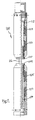
- the housing component 48 is open-spoked (see Fig 2 ), whereby the space 49 is included in chamber 23.
- the slider 24 is also open-spoked (see Fig 3 ), whereby the space 50 is also included (hydraulically) in the chamber 23.
- the coil housing 46 has slots 54 to accommodate the spokes of the slider 24.
- An electric cable 42 leads down from the surface. Leads (not shown) convey power to the opening-solenoid 38 and the closing-solenoid 37. Other items electrically connected to the surface include Instruments (not shown), such as pressure transducer, etc.
- the core 43 When the upper closing-solenoid 37 is energised, the core 43 is urged upwards.
- the slider 24 is operationally unitary with the core 43 to form a core/slider 45 ( Fig 6 ).
- Most of the components of the apparatus are of stainless steel; however, the core 43 itself Is of a magnetic material.
- the core Is free-sliding inside the coil housing 46.
- Solenoids work by creating a force urging the core to move, axially, to a position where the magnetic material is evenly disposed between the two ends of the solenoid; thus, the core -- that is to say, the magnetisable portion of the core -- should be disposed well off to one side, axially, of the coil.
- This is simple to provide, in respect of both solenoid coils, when the coils are disposed end to end, as seen in Fig 1 . That is to say, a core passing through both solenoids is well off-centre with respect to either coil individually.
- the solenoids 37,38 are so operated as to reciprocate the core/slider unit 45.
- a typical reciprocating cycle is in the region of one to three Hertz.
- cycling at speeds faster than about 0.5 Hz would not be advisable.
- the slowest rate, beyond which the apparatuses as depicted herein would hardly offer any advantage, would be, say, once every thirty seconds. Reciprocation continues for periods that are measured in hours or days.
- the gap 25 should move from closed to full-open violently, i.e in the shortest possible time. It is recognised that this time can be as small as the desired fifteen milliseconds, in an injector that functions reliably over a long service life, if the apparatus is designed as described herein.
- the gap 25 preferably is structured as axially-short / diametrally-large.
- the alternative, i.e axially-long/diametrally-small, is much less preferred, from the standpoint of rapidly creating a very large opening.
- One reason for preferring a gap that is axially-short/ diametrally-large, Is that only a small magnitude of movement of an axially-moving component Is needed to rapidly create a very large opening. Maximising the diameter of the gap 25 minimises the axial movement of the slider 24 that is needed in order to achieve the desired flowrate. Another reason is that solenoids are more efficient when exerting their forces over a small working travel.
- the valve should be designed such that the gap 25 is of the maximum diameter that can reasonably be accommodated within the casing of the wellbore,
- the outside diameter of the slider 24 is slightly less than the outside diameter of the outer body 36, in order that the (movable) slider 24 may be protected from being banged against the casing 27 walls as it goes down the borehole. But apart from that, the slider 24 and the gap 25 are as diametrally close to the overall diameter as possible.
- the slider 24 is driven downwards quite forcefully when the valve is opened, and the core/slider 45 thus strikes hard against a stop plate 53. Hydraulic or mechanical cushions (not shown) can be arranged to soften that impact, if that is a problem.
- a plurality of injector apparatuses may be mounted one above the other in the wellbore 26.
- the several injectors are positioned at appropriate depths relative to respective perforated zones of the casing 27.
- the Injectors are fed with pressurised liquid, all from the same source at the surface, the liquid being transferred through the respective hollow chambers 23 from injector to injector.
- a choke in the form of a small orifice 56 is provided. Liquid can pass through the choke, and slow changes in pressure can therefore gradually equalise, but rapid changes in pressure cannot pass through the choke.
- a check valve 57 enables liquid under pressure to be fed down to the injectors below, but prevents pressure surges from travelling upwards.
- a major reason for desiring a rapid opening of the gap 25 is to create a seismic pulse, having enough energy to propagate a pulse of increased porosity a significant distance out Into the surrounding formation. It is the rate of increase of flowrate over a (short) period of time that dictates the energy of that seismic or porosity wave. Given that the flowrate is (more or less) directly proportional to the width of the gap (for a constant pressure differential), therefore, the designer's aim should be to move the slider from closed to full-open in as short a time as possible.
- Fig 7 is a graph showing the flowrate through the gap 25 over a period of time.
- the gap is held closed, and the flowrate is zero.
- the gap starts to open, and the rate at which the gap opens, i.e the speed of the slider in millimetres per second, accelerates from zero.
- the slider has reached its top speed, and now the slider moves at constant (high) speed for the rest of its travel.
- the slider starts to decelerate, as the gap becomes full-open, and then the slider remains stationary in the full-open condition.
- the gap 25 Is increasing during the period between 60 and 62, and the flowrate is correspondingly increasing.
- the flowrate remains constant, as at 63.
- Most of the bulk of the charge-volume is injected or discharged out into the formation after the gap has reached this full-open stage, whereas the seismic wave, i.e the dynamic flow component of the whole wave, is created at the start of the period of opening, between 60 and 62, while the slider is moving.
- the more rapidly the gap opens the greater the rate at which the charge-volume is injected into the formation. In other words, the faster the flowrate increases, i.e the steeper the slope of the ramp portion 64 of the graph, the greater the energy of the ensuing porosity wave.
- the designer's aim is to create a valve in which the valve goes from full-closed to full-open in the shortest possible time.
- the graph embodies the assumption that the flowrate (in litres per second) is a constant multiple of the gap (in millimetres).
- the linearity is idealised, but it is suggested that the actual graph will be close enough to the true linear for the idealisation not to matter.
- the slider will not accelerate smoothly, as shown, and then maintain a constant speed of opening -- but it can be expected to do so approximately.
- the engineer could take account of the non-linearities, Inertia effects, and other departures from the assumed ideal, but it Is considered unlikely that doing so would lead to significantly better results than taking the simple ideallsed case, as shown.
- the graph of changing flowrate vs time (in litres per second per second), as shown in Fig 7 , can equally be regarded as a graph of changing gap size vs time (in millimetres per second).
- the flowrate vs gap relationship only remains linear so long as the pressure differential across the gap remains constant, as discussed below.
- the slope of the ramp portion is defined as follows.
- the full-open gap, termed G-100% is first ascertained. (In the illustrated apparatus, it was 7.62 mm). The full-closed gap is zero. Now, two more dimensions of the gap are ascertained. The first 65 of these is the one-fifth gap, G-20%, which in the illustrated apparatus would be 1.52 mm. The second 67 is the four-fifths gap, G-80%, which in the illustrated apparatus would be 6.10 mm.
- the dimension 68 measured as a change in the gap dimension, is the difference in mm between G-80% and G-20%.
- the dimension 68 also corresponds to a change in the flowrates; that is to say, the dimension 68 also is the difference between the flowrate (in litres/sec) when the gap was G-80% and the flowrate when the gap was G-20%.
- the ramp slope that is of interest in determining the energy of the seismic or porosity wave Is defined as the difference 68 between the G-80% flowrate (in litres per second) and the G-20% flowrate, divided by the time 69 taken for the slider to move from the G-20% gap to the G-80% gap.
- the ramp slope that is actually measured is the difference between the G-80% gap (in millimetres) and the G-20% gap, divided by the time 69.
- the steeper the ramp portion 64 of the graph the more energy is contained in the seismic wave.
- the portion of the graph between G-20% and G-80% has been selected because it is between those values that the slope of the ramp is at its steepest. If the slope were measured over the whole range, from G-0% to G-100%. the figure for the slope would then be misleadingly smaller. From the standpoint of creating an energetic seismic wave, it is the maximum slope, not the overall slope, that counts, assuming the maximum Is sustained over a substantial period of time -- such as the period between G-20% and G-80%, for example. In a particular case, if it were known that the maximum slope was already present at a gap of G-10%, for example, that could be used instead, in determining the slope of the ramp.
- the time 69 being the time period between G-20% and G-80%, should be no more than about fifty milliseconds (and preferably no more than about fifteen milliseconds). It is recognised that if the period 69 is longer than that, the pressure pulse might not have enough energy to create a useful porosity wave in the surrounding formation. There is no preferred lower limit to the period, expect that of the mechanical engineering demands a shorter period would impose on the apparatus.
- Fig 7 is a graph of flowrate vs time, and shows a typical pulsing configuration, over several pulsing cycles. In this case, it will be noted that the slider closes (almost) as quickly as it opened. The sudden reduction in flowrate, if rapid enough, can also cause a seismic wave to propagate out into the formation.
- Fig 10 shows the approach of this condition. Once the slider has been closed, and the gap is once more zero, now the pressure in the liquid upstream of the (now closed) gap can once more be pressurised. It might take some time to re-pressurise the upstream liquid to the magnitude required for an energetic seismic wave.
- the closed portion, between cycles might not be very small, as in Figs 8,9 , but might need to be a longer proportion of the whole cycle, as in Fig 10 .
- the reservoir in which the pressurised liquid is stored should be, not only of high volume, but also should be connected to the gap by a conduit of large cross-sectional area -- there would be no point in providing a large gap if the conduit leading to the gap were restricted.
- the conduit in this case includes the annular passageway 72 leading from the reservoir.
- the gap 25 is forty cm in circumference, and the gap, when fully open, is 7.62 mm axially.
- the area available for conveying flow is around thirty sq.cm.
- the conduits leading to the gap should have a greater flow-conveying area than that, preferably by a large margin.
- Fig 11 now the pulses are carried out at a greater frequency, such that the gap starts to close even before it has fully opened. Still, the slope of the ramp portion determines the seismic component.
- the higher cycling frequency usually is done when the ground is reaching its limits of saturation, i.e when not much more volume of liquid can be forced into the formation, per cycle - which is likely to be when the high-energy seismic component can be most advantageous, i.e when the ensuing porosity wave suffers the least attenuation, and hence propagates a further distance.
- the slope of the ramp 64 is the same. In all the illustrated variations, it is the steepness of the slope of the ramp portion 64 that determines the energy of the seismic wave. Thus, all the variations can be expected to create seismic waves of about the same energy. The variations may be regarded as resulting from the situational and mechanical compromises in an apparatus that has been designed to maximise the steepness of that slope.
- the gap 25 will crack open, first, at one particular point on the circumference of the gap, while other points on the circumference of the gap are still touching. Then, the other points around the circumference of the gap will open progressively, until finally no part of the circumference is touching. With reasonably precise manufacturing accuracy, it can be expected that the progressive or gradual opening is completed well before the G-20% gap (point 65 in Fig 7 ) Is reached.
- the balance-seal 40 diameter should be equal to, or only slightly larger or smaller than, the sealed diameter of the gap-seal 73, i.e the diameter at which the sealing face 34 makes contact with the seat face 35.
- the gap-seal diameter is about twelve cm, of course the solenoid 38 cannot be expected to supply enough force to open the gap against the force resulting from that pressure applied to the whole area of the slider.
- the solenoids can be expected to supply no more than about 1000 N, typically, whereas the force generated by a pressure differential in the region of 5 MPa, acting over a twelve-cm-diameter area is several tonnes. That is why the slider is mounted between diameter-balanced seals.
- the seal 40 is a balance-seal, which balances, or almost balances, the gap-seal 73.
- the space 50 is part of, or communicates with, the chamber 23, whereby the hydraulic pressure differential is the same across the gap-seal 73 as across the balance-seal 40.
- the hydraulic pressure would exert no net biassing force on the slider. If the balance-seal 40 diameter is slightly smaller than the gap-seal 73 diameter, the hydraulic pressure exerts a net force tending to urge the slider towards the open condition; if the balance-seal 40 diameter is made a little larger than the gap-seal 73 diameter, the hydraulic pressure exerts a net force tending to urge the slider towards the closed condition. As mentioned, biassing the slider towards the open condition is preferred.
- the magnitude of the out-of-balance biassing force (attributable to the difference in diameter between the gap-seal 73 and the balance-seal 40) can advantageously be arranged to overcome the seal friction inherent in the balance-seal 40 at high pressure differentials, or to contribute substantially to overcoming the seal-friction, bearing in mind that the springs 39 also contribute towards overcoming the seal-friction.
- a key function of the apparatus as described herein is to provide that the slider 24 opens very rapidly, and the large friction forces attributable to the balance-seal 40 count against that function.
- the balance-seal can be made of low-friction material, such as PTFE. It can be difficult to ensure that such materials make an absolutely tight seal at very low pressure differentials, but that is not too important in this case, In that the balance-seal, like the gap-seal, is not required to seal absolutely, when closed.
- the balance-seal takes the form of a tight clearance between a sleeve 74 of the moveable slider 75, and a corresponding diameter 76 of the fixed component 78 of the apparatus.
- the tight clearance extends over a long axial distance.
- Such a seal is not, of course, capable of sealing one hundred percent -- but that is not required.
- the requirement is to enable a pressure differential of e.g 5 MPa to obtain for a period of a second or two -- and a long, tight clearance can be expected to accomplish that.
- FIG. 12 Another difference between the apparatus shown in Fig 12 and that shown in e.g Fig 1 is that, in Fig 12 , the solenoid coils 79 move with the slider while the core 80 remains stationary.
- the portion 82 of the core between the coils is made of magnetic iron, while the portions of the core 80 outside the portion 82 are, like the rest of the metal components of the apparatus, of (non-magnetic) stainless steel.
- a disadvantage of having the coils move is that the leads and cables conveying electricity to the solenoids have to cope with the movement. However, the movement is not large.
- An advantage is that there is no need for the spoked construction, as in Figs 1,3 , wherein radial spokes are required to form a structural bridge, through the moving slider, between the stationary central core 43 and the annular stationary components 48,50.
- the choke and the check valve as illustrated in Fig 1 are not present.
- the Fig 12 injector would not be not suitable for use in tandem with other devices in the same borehole, where liquid to be injected is passed through from injector to injector.
- the designer may prefer to arrange the solenoids inside-cut, i.e with the coils thereof located inside a tubular magnetic core: in that case, not only are bridging spokes not needed, but also the electrical wires do not need to cope with movement.
- both the seal-face and the seat are on components that both move axially, relative to the non-moving housing of the apparatus.
- the seal-face is driven downwards, while the seat Is driven upwards (or vice versa).
- one component is attached to and moves with the solenoid core, and the other component Is attached to and moves with the solenoid coil.
- four solenoids are used: upper opening solenoid 101, upper closing solenoid 103, lower opening solenoid 105; and lower closing solenoid 107.
- the seal-friction is enough to keep the slider 84 from moving downwards; the only force driving the slider downwards at this time is the out-of-balance force attributable to the difference between the diameter of the balance-seal 40 and the diameter of the gap-seal 87, and the designer can easily see to it that this force Is smaller than the seal-friction.
- the slider 84 does not start moving downwards until the abutment face 85 strikes the boss 89 of the slider 84.
- the core is already up to full speed, and therefore adds its momentum to the force available from the lower opening solenoid 88, and from the springs, to drive the slider.
- the slider now accelerates very smartly indeed from the closed to the open position.
- One benefit of the Fig 13 arrangement is that the heavy components have started to move, and are already travelling very fast, by the time they strike the slider, and jerk the balance-seal free.
- acceleration-inhibiting factors as inductive-hysteresis of the coils, slack take-up, inertia of heavy parts, low-rate elasticities, and the like, are all overcome already, before the seal Itself starts to open.
- Fig 1 when the slider 24 is moved upwards to the closed condition, the slider contacts the gap-seat 35 on a metal-to-metal basis. This contact is likely to be quite forceful, and, since the hammering contact is repeated, typically, every few seconds (and will likely include bouncing/rebounding), it might happen that the contacting faces become worn, over a long period of service.
- Figs 14a,b show the use of an elastomeric seal-block 90. When the slider closes against the seat face 35, much of the hammer impact is absorbed, given the elastomeric nature of the material.
- the diameter of the balance-seal 40 should now be slightly larger than the diameter of the gap-seal, to ensure that the gap-seal remains closed until the seal-block 90 is picked up and slammed downwards by the slider 93.
- valve gap preferably should be as large diametrally as possible, in order to maximise the flow-conveying area for a given axial travel.
- the outside diameter of the slider 24 is only slightly less than the overall diameter of the outer body 36 -- being slightly less in order that the (movable) slider 24 may be protected from striking against the casing 27 walls as it goes down the borehole. But apart from that, the slider 24 and the gap 25 are as diametrally large as possible.
- the gap seal/seat engagement diameter should preferably be not less than about twelve cm.
- the gap 25 preferably should be as large, diametrally, as possible, given the mechanical constraints of the structure. If the designer is aiming to make the seals as large as possible within the apparatus, and within the limits imposed by unavoidable structural requirements, it Is simple enough to provide that the seal diameters would be less than ten millimetres Inside the overall diameter of the downhole apparatus. (Usually, the seal diameter can be within five millimetres of the overall diameter.) Thus, where the overall diameter is thirteen cm, the seal diameters can be twelve or 121 ⁇ 2 cm. At such diameters, an adequate axial opening of the gap can be achieved if the slider moves axially about seven or eight millimetres.
- either of the two seal diameters may be the larger, depending on whether the designer wishes to bias the slider open or closed.
- the seal-groove should be cut in the male component, not in the female component. If the seal-groove were cut in the female component, the female component, which lies outside the seal diameter, would have to be radially thicker, which would limit the seal diameter of the balance-seal.
- the difference between the diameter of the valve-gap-seal and the diameter of the balance-seal will be less than one millimetre. Even that difference might be too large, in that, at twelve cm diameter, and over an annular width of one millimetre, a pressure differential of five MPa represents a force of 1885 N -- which might be greater than the force that can conveniently be brought to bear by the opening-solenoid -- whereby, at least at the higher pressure differentials, preferably, the difference in effective-seal-diameter between the gap-seal and the balance-seal should rather be not more than about 1 ⁇ 2mm.
- the designer must, of course, provide an opening solenoid of enough force capacity as to open the valve under the conditions likely to be encountered during use; either that, or the designer should taylor the conditions of use to the force available from the solenoid.
- Figs 16a,16b show another variant.
- the slider 120 is driven to move by the solenoid motor 121.
- the solenoid 121 holds the slider 120 in its UP position.
- the valve-face 123 on the slider 120 is in sealing engagement with the valve-seat 125 on the housing 127.
- An O-ring 129 is provided to make sure of the efficacy of the whole valve-seal 130.
- the slider 120 also includes a balance-seal 132, comprising a balance-face 134 on the slider 120 and a balance-seat 136 on the housing 127. Again, an O-ring 138 is provided to make sure of the efficacy of the balance-seal 132.
- the balance-seal 132 also opens, more or less simultaneously. Therefore, the balance O-ring 138 will not be subjected to being dragged over a metal surface. Over a long service period, this reduces abrasive wear and seal friction.
- Figs 16a,16b are diagrammatic, and do not show details of the actual structures. Obviously, the designer must see to it that the structures are manufactured in separate components which can be assembled together. However, it will be understood that the valve-seat 125 and the balance-seat 136, even if it were possible to produce these seats in the same single piece of material as diagrammatically shown (which of course is not physically possible), are likely to run into problems of manufacturing tolerances, and into problems of ensuring the concentricity and squareness of the various faces and seats. It should be noted that these problems will or might arise in some of the other design variants, and equivalent measures can then be taken, as will now be described.
- valve-face 123 and the valve-seat 125 of the valve-seal 130 lie nominally In a plane perpendicular to the axis of the cylindrical housing 127. It is important that the valve-face 123 and the valve-seat 125 touch properly together around the whole circumference. If the face and the seat were to touch at the north side of their circumference, and yet leave a gap at the south side, due e.g to a build-up of small misalignments, the function of the valve-seal 130 will be compromised; perhaps to the extent of making it impossible to build up enough pressure differential across the valve-seal to ensure a strong high-energy seismic wave.
- the slider 120 takes its concentricity from the balance-seal 132; the slider 120 can rock (slightly) angularly within the balance-seal 132, and thus the slider 120 can come to rest, when urged upwards into the closed position, with the valve-face 123 perfectly flat-against-flat onto the valve-seat 125.
- the slider 120 should be loose enough upon the core 140 of the housing 127 that it can rock sufficiently to accommodate all the mismatches and misalignments likely to be encountered. Given that the metal faces can be truly flat-to-flat, the designer might decide to dispense with the O-ring 129, although it would be prudent to retain it.
- the O-ring 138 in the balance-seal 132 might be dispensed with, but it would be prudent to retain it.
- the balance-seal 132 should have the same, or almost the same, seal-diameter as the valve-seal 130.
- a shock-absorber in the form of O-ring 141 is provided, to absorb some of the impact of the slider 120 being hurled against the housing 127.
- an hydraulic cushion may be provided, e.g of the traditional kind as used in conventional hydraulic or pneumatic rams to absorb the shock of the piston slamming solidly against the end of the cylinder.
- FIG. 17 is a diagrammatic view of an injector, from which much of the practical detail has been omitted.
- the designer of an apparatus that is to be lowered down the borehole will generally see to it that the apparatus 145 is right-cylindrical, of a smaller overall diameter OD than that of the borehole casing BCD. Within that confine, the designer will wish to maximise the outer diameter OD of the apparatus. Often, an apparatus will not be quite circular, in that it might have protruding screw-heads or the like. In Fig 17 , the overall diameter OD cm should therefore be regarded as the diameter of the cylinder that circumscribes the apparatus 145. This circumscribing circle has a circumference OC cm, and the area enclosed within the circle has an area of OA sq.cm.
- Liquid is fed down from a pressure source or reservoir at the surface (not shown in Fig 17 ) to a near-valve reservoir 147.
- the reservoir is charged with the pressure due to a body of compressed nitrogen in an accumulator 149, which also is supplied and controlled from the surface.
- the near-valve reservoir has a (comparatively large) cross-sectional area RA sq.cm.
- conduit 150 From the near-valve reservoir 147, liquid travels via a conduit 150 to the valve-gap 152.
- the conduit 150 will not be of constant uniform cross-sectional area, in that the conduit might include the open-spoked configuration, with windows and passages of various profiles and sizes as described in relation to the other design variants.
- the conduit cross-sectional area CA sq.cm should be measured as the minimum through-flow-conveying cross-sectional area that Is encountered by the liquid as it passes along the length CL of the conduit, between the (larger) reservoir area RA sq.cm and the valve-gap 152.
- the conduit should be short, i.e being less than ten times the overall diameter OD of the downhole-structure.
- valve-face 154 on the slider 156 and the valve-seat 158 on the housing 160 are complementarily conical. It will be understood that, in the closed condition, the valve-face 154 and the valve-seat 158 make touching, sealing contact over an annular contact-area.
- the balance-seal has a seal-diameter and a seal-area BSA, which is computed in a similar way.
- valve-gap-seal-circumference VGSC cm The relationship between the valve-gap-seal-circumference VGSC cm and the circumference of the circumscribing circle OC cm is important.
- the designer should aim to make VGSC as large as possible, given the strictures of the overall cylindrical shape. It is usually easy enough to design the apparatus such that VGSC is more than 90% of OC. If VGSC is less than 85% of OC, that is less preferred. And if the designer has made VGSC less than about 75% of OC, that is an indication that the designer is not seeking to make the best and most efficient use of the available geometry to provide an energetic seismic component.
- valve-gap-throat-area VGTA sq.cm is another relationship of importance.
- the valve-gap-throat-area VGTA sq.cm is another relationship of importance.
- valve gap G-100% equals the actual full-open valve-gap, unless the valve-gap-throat-area at that full-open condition exceeds the conduit-area, in which case the full-open valve-gap G-100% is deemed to be the gap at which the valve-gap-throat-area is equal to CA.
- the designer preferably should make CA somewhat larger than VGTA, and it is suggested that the valve-gap and the conduit area should be engineered, together, so that CA sq.cm is about 20% larger than VGTA sq.cm.
- the designer should seek first to maximise the conduit area CA sq.cm, and then design VGTA to suit. If the conduit has to be long and tortuous, then CA should be closer to 30% larger than VGTA. If the conduit is short and straight and open (as it is shown diagrammatically in Fig 17 ), then the designer preferably would make CA about 10% larger than VGTA.
- VGTA should not be less than 40% CA as a lower limit, and preferably VGTA should not be less than 50% of CA sq.cm.
- valve-gap-throat-area VGTA sq.cm Another relationship of importance is that between the valve-gap-throat-area VGTA sq.cm and the overall area OA sq.cm inside the circumscribing circle.
- a designer who is seeking to maximise the energy of the seismic components of the pulse cycles should be able to make VGTA larger than about 20% of OA. If VGTA is below that, that is an indication that the apparatus has not been designed to make the best use of the cylindrical shape of the downhole environment to produce high-energy seismic waves.
- the conduit should also be designed to be of a correspondingly high area CA sq.cm -- as mentioned, there is no point in VGTA being greater than CA (and again, for the purpose of calculating the flow-conveying cross-sectional area relationships, if the actual full-open valve-gap is larger than CA, the VGTA in the calculation is deemed to be equal to CA sq.cm).
- OA in an apparatus with an OD of 127mm, OA is 127sq.cm.
- a conduit area CA of 25% of OA is 31.7sq.cm, and a CA of 35% of OA is 44.3sq.cm.
- OA In a 95mm OD apparatus, OA is 71 sq.cm.
- a CA that is 25% of OA is 17.7sq.cm, and a CA that is 35% of OA is 24.8 sq.cm.
- the designer should stay within the above relationships in order to achieve an energetic seismic component. It is of little use to provide a valve that opens very rapidly if, due to other compromises, that rapidity of opening turns out not to be the critical factor in determining the flowrate at which the liquid can be injected out. Thus, the conduit 150 should be engineered to ensure that the liquid can flow out of the valve-gap 152 at the highest possible speed.
- the near-valve reservoir 147 should be large enough, and the accumulator 149 should be resilient enough, to maintain adequate pressure differentials throughout the whole period while liquid is being discharged.
- the rapid-opening valve-gap is not functional in Itself -- it has to be backed up by an apparatus that has ability to convey large volumes through the open valve-gap at large flow rates.
- the near-valve-reservoir should have a capacity of at least half a litre (for use in boreholes in the 90mm to 130mm diameter range), as will now be discussed.
- An apparatus that is capable of doing surge-pulsing will typically be able to inject several litres of liquid, per pulse (i.e per cycle). Typically, that charge-volume of liquid is fed down from a pressure source or reservoir at the surface (i.e a reservoir other than the near-valve reservoir 147). But the conduits that lead down from the surface typically are too narrow and too long to permit a large enough throughflow velocity to create much of a seismic pulse - - which is why the near-valve reservoir is provided.
- the near-valve reservoir may be dispensed with.
- the liquid that is to be injected very rapidly, for creating the seismic component, at the start of the outflow portion of the surge-pulsing cycle will need to be stored close to the valve, and will need to be connected to the valve by a wide conduit.
- the computations mentioned above that refer to the various dimensions of the conduit apply to the short conduit that connects the near-valve reservoir to the vaive-gap.
- the volume of liquid that is to be stored in the near-valve reservoir need not be the whole several litres of the whole per-cycle charge-volume.
- the volume stored near the valve need only be enough to power the seismic wave.
- the rest of the litres required for the charge-volume can be fed down, relatively slowly, from the surface, in the usual way.
- the near-valve reservoir preferably should have a capacity of at least half a litre.
- the purpose of the gas-charged accumulator 149 is to maintain the high pressure of the near-valve reservoir 147 during the rapid injection. If desired, once the near-valve reservoir has received a full volume of liquid, the nitrogen can be given a boost of still-higher pressure, from the surface, just prior to opening the valve. Then, after the wave has been created, the nitrogen pressure can be released, e.g during the backflow portion of the cycle, to allow the near-valve reservoir once more to be recharged.
- the pressure in the near-valve reservoir should be at least one (preferably two) MPa above the in-ground pressure.
- the reservoir/ accumulator can be charged up during the backflow portion of cycle, so the stored liquid at high pressure is once more ready to create a new seismic wave at the commencement of the next outflow portion of the cycle.
- solenoids are shown as drive-motors for driving the valve-member or slider, but other types of forceful drive-motors can be used instead.
- the featured details of the various designs illustrated herein may be advantageously interchanged in the other illustrated designs; that is to say, designers should regard the different features as being interchangeable between the various designs, unless otherwise indicated.
- the apparatuses as described herein are designed for use (when suitably scaled) in boreholes In the range in the range 30cm down to 3 cm.
- the on-site engineers must of course be aware of the depth at which the borehole perforations are located, and must see to it that the valve-gap is located very close to that depth when it opens. If the valve is too far from the perforations, the seismic waves might be attenuated too much to be useful. It is important, too, that the volume of water inside the borehole, but outside the down-hole-structure, be kept small. If that volume is large, too much of the energy of the pulse might be dissipated inside the borehole, without passing through the perforations and out into the formation around the borehole.
- the size of the down-hole structure should be chosen to almost fill the borehole, and the packers should be located just above the downhole-structure (and just below the downhole-structure If that, too, needs to be closed off).
- seismic waves and seismic components of waves and pulses, and similar, have been used herein.
- these expressions be understood to refer to the type of wave, or rather to the type of wave profiles, that are induced in the ground around a borehole when a stored volume of high pressure liquid is released into the ground very rapidly.
- the waves should have a large enough energy content to be detectable or measurable a distance of at least five metres radially away from the borehole. It is expected that the waves will be detectable much further away than that in many cases: but if the waves cannot be detected at the stated minimum of five metres, it is considered that the wave is too weak to provide any worthwhile contribution to improving the conductivity and liquid-injectability of the ground. For example, if the ground is not fully saturated with liquid, or if the liquid is not coherent over a large volume around the borehole, the induced waves might not propagate in a worthwhile and effective manner. Similarly, if the speed of opening the valve-gap is too slow, or the induced pressure differential that is responsible for forcing liquid out of the borehole is too small, again the induced seismic wave might not propagate in a worthwhile and effective manner.
Landscapes
- Life Sciences & Earth Sciences (AREA)
- Engineering & Computer Science (AREA)
- Geology (AREA)
- Physics & Mathematics (AREA)
- Mining & Mineral Resources (AREA)
- Environmental & Geological Engineering (AREA)
- General Life Sciences & Earth Sciences (AREA)
- Fluid Mechanics (AREA)
- Remote Sensing (AREA)
- Geochemistry & Mineralogy (AREA)
- Acoustics & Sound (AREA)
- Geophysics (AREA)
- General Physics & Mathematics (AREA)
- Consolidation Of Soil By Introduction Of Solidifying Substances Into Soil (AREA)
- Details Of Valves (AREA)
- Magnetically Actuated Valves (AREA)
- Geophysics And Detection Of Objects (AREA)
Claims (15)
- Appareil pour superposer une onde sismique sur un écoulement de liquide étant injecté dans le sol autour d'un trou de sonde (26), caractérisé par la combinaison suivante de caractéristiques :l'appareil comporte un réservoir (23) pour stocker, sous pression, le liquide à injecter dans le sol ;l'appareil comporte une structure de fond de trou (20), qui est appropriée pour descendre dans le trou de sonde (26) ;la structure de fond de trou (20) a une circonférence globale, étant la circonférence qui circonscrit toutes les parties de la structure de fond de trou,la circonférence globale mesure l'OC en cm de longueur, mesurée dans un plan perpendiculaire à l'axe du trou de sonde (26) ;la structure de fond de trou (20) comporte une vanne, comprenant une face de vanne (35, 110, 123, 154) sur un élément de vanne, et un siège de vanne (34, 109, 125, 158) mobile par rapport à l'élément de vanne ;la vanne est actionnable entre un état fermé et un état complètement ouvert ;dans l'état complètement ouvert, la face de vanne (35, 110, 123, 154) est séparée du siège de vanne (34,109, 125, 158) et est espacée de celui-ci par un interstice de vanne (25) ;dans l'état fermé, la face de vanne (35, 110, 123, 154) et le siège de vanne (34, 109, 125, 158) établissent un contact d'étanchéité sur une zone de contact annulaire ;une ligne de contact de joint d'interstice de vanne est définie comme le lieu du point médian de ladite zone de contact annulaire au niveau de chaque rayon autour de la ligne de contact de joint d'interstice de vanne ;la ligne de contact de joint d'interstice de vanne a une circonférence de joint d'interstice de vanne (VGSC), qui mesure la VGSC en cm ; etla VGSC (circonférence de joint d'interstice de vanne) est supérieure à soixante-quinze pour cent de l'OC (circonférence globale) et de sorte que la structure de fond de trou (20) comporte un boîtier fixe (46, 127, 160), et l'élément de vanne comprend un coulisseau (24, 75, 84, 93, 120, 156) qui peut coulisser axialement à l'intérieur du boîtier (46, 127, 160), entre les états ouvert et fermé, et l'appareil comporte un moteur d'activation de vanne actionnable qui est efficace, lorsqu'il est actionné, pour ainsi déplacer le coulisseau (24, 75, 84, 93, 120, 156).
- Appareil selon la revendication 1, dans lequel la VGSC (circonférence de joint d'interstice de vanne) est supérieure à quatre-vingt-cinq pour cent de l'OC (circonférence globale).
- Appareil selon la revendication 1 ou la revendication 2, caractérisé en outre en ce que :la structure de fond de trou (20) est structurellement capable d'être abaissée dans un trou de sonde (26) de sorte que la structure de fond de trou a un profil transversal, pris perpendiculairement à l'axe du trou de sonde (26), qui s'adapte à l'intérieur d'un cylindre droit circonscrit de diamètre plus petit que le trou de sonde (26) ; etla circonférence globale OC en cm est la circonférence de ce cylindre droit, qui a un diamètre qui mesure l'OD en cm, et une zone fermée qui mesure l'OA (cm2).
- Appareil selon la revendication 3, caractérisé en outre en ce que :l'appareil comporte un conduit (49) pour transporter le liquide du réservoir (23) à la vanne ; le conduit (49) a une zone de conduit transversale qui mesure la CA (cm2) ; la zone de conduit CA est définie comme la zone transversale la plus petite disponible pour le transport du liquide, mesurée sur toute la longueur du conduit (49) du réservoir (23) à l'interstice de vanne (25) ; etla CA (cm2) est supérieure à vingt-cinq pour cent de l'OA (cm2) ; l'interstice de vanne (25) a une zone de gorge d'interstice de vanne VGTA (cm2), étant la zone transversale minimale de l'interstice de vanne (25) à travers lequel le liquide s'écoule lors du passage à partir du conduit (49), depuis l'intérieur de l'interstice de vanne (25), vers l'extérieur de l'interstice de vanne (25) ;et la plus petite parmi la CA et la VGTA est supérieure à vingt pour cent de l'OA, et est de préférence supérieure à trente pour cent de l'OA.
- Appareil selon la revendication 5, caractérisé en outre en ce que la zone de conduit CA est supérieure à la VGTA et est de préférence supérieure à 110 % de la VGTA.
- Appareil selon la revendication 1 ou 2, caractérisé en outre en ce que :dans l'état fermé de la vanne, la longueur axiale VGL (longueur d'interstice de vanne) de l'interstice de vanne (25) est nulle, ou G-0 % en cm ;G-100 % est la plus petite des valeurs suivantes : soit (a) la longueur axiale de l'interstice de vanne (25) lorsque la vanne est dans son état complètement ouvert ; soit (b) la longueur axiale de l'interstice de vanne (25) dans un état partiellement ouvert à laquelle la zone de gorge d'interstice de vanne est égale à la zone de conduit CA (cm2) ;à des ouvertures intermédiaires de l'interstice de vanne (25), l'interstice de vanne (25) a une longueur axiale de G-X %, où X est un pourcentage de l'ouverture entre G-0 % et G-100 % ;le moteur d'activation de vanne est actionnable pour entraîner le coulisseau (24, 75, 84, 93, 120, 156) avec une telle rapidité que l'interstice de vanne (25) passe d'un interstice G-20 % à un interstice G-80 % (67) dans une période de temps T-20-80 qui mesure moins de cinquante millisecondes.
- Appareil selon la revendication 1 ou la revendication 2, caractérisé en outre en ce que :la structure de fond de trou (20) comporte un boîtier fixe (46, 127, 160) ;la circonférence de joint d'interstice de vanne VGSC enferme une zone qui mesure la VA (cm2) ;la structure de fond de trou (20) comporte un joint d'équilibrage (132), comprenant une face d'équilibrage (40) et un siège d'équilibrage (136), dont l'un est inclus dans le boîtier (46, 127, 160) et dont l'autre est inclus dans l'élément de vanne ;dans l'état fermé de la vanne, la face d'équilibrage (40) touche le siège d'équilibrage (136) au-dessus d'une zone de contact de joint d'équilibrage annulaire ;une ligne de contact de joint d'équilibrage est définie comme le lieu de points médians de la zone de contact d'équilibrage annulaire au niveau de chaque rayon autour de la zone de contact de joint d'équilibrage ;la ligne de contact de joint d'équilibrage a une circonférence, et la zone enfermée à l'intérieur de cette circonférence et exposée à la pression du liquide provenant du réservoir (23) mesure la BA (cm2) ;la ligne de contact de joint d'équilibrage est exposée à, et supporte le même différentiel de pression que la ligne de contact de joint de vanne ; etla zone BA se situe dans les limites de cinq pour cent de la zone VA ; grâce à quoil'élément de vanne, dans l'état fermé de la vanne, est soumis à une force nette résultant de la différence de zone entre BA et VA dans le sens de déplacement de la vanne entre les états fermé et complètement ouvert, d'au plus cinq pour cent de la force dudit différentiel de pression agissant sur la zone VA.
- Appareil selon la revendication 7, caractérisé en outre en ce que l'appareil est ainsi structuré de sorte que, lorsque l'état de vanne passe de fermé à complètement ouvert, la face d'équilibrage (40) reste en contact avec le siège d'équilibrage (136).
- Appareil selon la revendication 7, caractérisé en outre en ce que l'appareil est ainsi structuré de sorte que, lorsque l'état de vanne passe de fermé à complètement ouvert, la face d'équilibrage (40) rompt le contact avec le siège d'équilibrage (136), sensiblement simultanément à mesure que la face de vanne (35, 110, 123, 154) rompt le contact avec le siège de vanne (109, 125, 158).
- Appareil selon la revendication 1 ou la revendication 2, caractérisé en outre en ce que :le moteur d'activation de vanne comporte un solénoïde d'ouverture (38, 101, 105), d'une structure telle que, lorsqu'il est excité, le solénoïde d'ouverture (38, 101, 105) pousse l'élément de vanne de l'état fermé à ouvert ; etle moteur d'actionnement de vanne comporte un solénoïde de fermeture (37, 103, 107), d'une structure telle que, lorsqu'il est excité, le solénoïde de fermeture (37, 103, 107) pousse l'élément de vanne de l'état ouvert à fermé.
- Appareil selon la revendication 10, caractérisé en outre en ce que :le solénoïde est fixé à l'intérieur du boîtier fixe (46, 127, 160) ;le moteur d'activation de vanne comporte un noyau (43, 80), situé radialement à l'intérieur du solénoïde, et le noyau (43, 80) est mobile axialement par rapport au boîtier fixe (46, 127, 160).
- Appareil selon la revendication 3, caractérisé en outre en ce que :l'appareil comporte un conduit (49) pour transporter le liquide du réservoir (23) à la vanne ;le conduit (49) a une longueur de conduit qui mesure la CL en cm ;la CL en cm est inférieure à dix fois l'OD (diamètre extérieur) en cm.
- Appareil selon la revendication 11, caractérisé en outre en ce que :le conduit (49) est formé à l'intérieur du boîtier fixe (46, 127, 160) de la structure de fond de trou (20) ;le coulisseau (24, 75, 84, 93, 120, 156) comporte une partie extérieure qui se situe radialement à l'extérieur du conduit (49) et une partie intérieure qui se situe radialement à l'intérieur du conduit (49) ;les parties intérieure et extérieure du coulisseau (24, 75, 84, 93, 120, 156) sont reliées par des rayons ; etles rayons se situent dans des ouvertures respectives dans le boîtier fixe (46, 127, 160), à travers lequel le liquide dans le conduit (49) peut passer librement entre les parties intérieure et extérieure du coulisseau (24, 75, 84, 93, 120, 156).
- Appareil selon la revendication 1 ou la revendication 2, dans lequel la zone de contact annulaire est une zone de contact annulaire conique ; et
la ligne de contact de joint d'interstice de vanne étant définie comme le lieu du point médian de ladite zone de contact annulaire conique au niveau de chaque rayon autour de la zone de surface annulaire. - Procédure d'injection de liquide dans le sol autour d'un trou de sonde (26), caractérisé par :la fourniture d'un appareil selon l'une quelconque des revendications 1 à 14 ;la mise en oeuvre du cycle suivant à une fréquence comprise entre trois fois par seconde et deux fois par minute :- dans une partie de sortie du cycle, la création d'un différentiel de pression positif dans l'appareil, dans lequel le différentiel de pression agit dans le sens pour pousser le liquide à l'intérieur du trou de sonde (26) pour sortir du trou de sonde (26) et pénétrer dans le sol, et dans lequel le différentiel de pression positif est suffisamment important, et la partie de sortie du cycle dure suffisamment longtemps pour qu'un volume de surpression d'au moins un litre de liquide sorte du trou de sonde (26) et pénètre dans le sol, par cycle ;- dans une partie de refoulement du cycle, la réduction suffisante de la pression dans l'appareil pour créer un différentiel de pression négatif dans le liquide à l'extérieur du trou de sonde (26), qui agit dans le sens pour pousser le liquide à l'extérieur du trou de sonde (26) vers le trou de sonde (26) ;- le stockage du liquide en amont de l'ouverture, sous haute pression, avec l'ouverture fermée, et, au début de la partie de sortie du cycle, l'ouverture soudaine de l'ouverture, libérant ainsi le liquide stocké à travers l'ouverture puis dans le sol autour du trou de sonde(26) ;- où l'amplitude de la haute pression et la vitesse de libération du liquide sous pression à travers l'ouverture sont suffisantes pour provoquer la propagation d'une onde sismique dans et à travers le sol autour du trou de sonde (26), l'onde étant une onde d'énergie suffisante pour qu'une perturbation attribuable à l'onde puisse être mesurée à une distance radiale d'au moins cinq mètres du trou de sonde (26).
Applications Claiming Priority (3)
| Application Number | Priority Date | Filing Date | Title |
|---|---|---|---|
| GB0518945A GB0518945D0 (en) | 2005-09-16 | 2005-09-16 | Rapid-opening valve for well bores |
| GB0604295A GB0604295D0 (en) | 2006-03-03 | 2006-03-03 | Rapid-opening valve for well bores |
| PCT/US2006/036170 WO2007100352A1 (fr) | 2005-09-16 | 2006-09-18 | Generation d'impulsions sismiques dans un trou de sonde a l'aide d'une vanne a ouverture rapide |
Publications (3)
| Publication Number | Publication Date |
|---|---|
| EP1994255A1 EP1994255A1 (fr) | 2008-11-26 |
| EP1994255A4 EP1994255A4 (fr) | 2015-04-08 |
| EP1994255B1 true EP1994255B1 (fr) | 2018-06-13 |
Family
ID=38459365
Family Applications (1)
| Application Number | Title | Priority Date | Filing Date |
|---|---|---|---|
| EP06824978.8A Active EP1994255B1 (fr) | 2005-09-16 | 2006-09-18 | Generation d'impulsions sismiques dans un trou de sonde a l'aide d'une vanne a ouverture rapide |
Country Status (6)
| Country | Link |
|---|---|
| US (1) | US8061421B2 (fr) |
| EP (1) | EP1994255B1 (fr) |
| AU (1) | AU2006339418B2 (fr) |
| BR (1) | BRPI0617008A2 (fr) |
| CA (1) | CA2621855C (fr) |
| WO (1) | WO2007100352A1 (fr) |
Families Citing this family (23)
| Publication number | Priority date | Publication date | Assignee | Title |
|---|---|---|---|---|
| CA2817943C (fr) | 2007-10-05 | 2015-02-24 | Canasonics Inc. | Systeme de pompe hydraulique |
| CA2712142C (fr) * | 2008-01-17 | 2015-11-24 | Wavefront Reservoir Technologies Ltd. | Systeme pour injection pulsee de fluide dans un trou de forage |
| GB0807878D0 (en) * | 2008-04-30 | 2008-06-04 | Wavefront Reservoir Technologi | System for pulse-injecting fluid into a borehole |
| US8113278B2 (en) * | 2008-02-11 | 2012-02-14 | Hydroacoustics Inc. | System and method for enhanced oil recovery using an in-situ seismic energy generator |
| GB0817500D0 (en) * | 2008-09-24 | 2008-10-29 | Wavefront Reservoir Technologi | Injection of liquid into boreholes, with suck-back pulsing |
| NO330266B1 (no) | 2009-05-27 | 2011-03-14 | Nbt As | Anordning som anvender trykktransienter for transport av fluider |
| EA024367B1 (ru) | 2009-09-04 | 2016-09-30 | Харолд Дж. Никайпело | Способ и устройство для интенсификации добычи углеводородов из буровых скважин |
| GB201002854D0 (en) * | 2010-02-19 | 2010-04-07 | Wavefront Reservoir Technologies Ltd | Magnet - operated pulsing tool |
| EA033089B1 (ru) | 2010-06-17 | 2019-08-30 | Импакт Текнолоджи Системз Ас | Способ, использующий импульсы давления в операциях извлечения углеводородов |
| US8869885B2 (en) * | 2010-08-10 | 2014-10-28 | Baker Hughes Incorporated | Fluid metering tool with feedback arrangement and method |
| RU2446269C1 (ru) * | 2010-09-28 | 2012-03-27 | Общество с Ограниченной Ответственностью "НОВАТЭК-ТАРКОСАЛЕНЕФТЕГАЗ" | Гидродинамический пульсатор |
| US9228418B2 (en) | 2011-12-14 | 2016-01-05 | Schlumberger Technology Corporation | Wave stimulation |
| AR089304A1 (es) | 2011-12-19 | 2014-08-13 | Impact Technology Systems As | Metodo para recuperacion de presion por impacto |
| GB2497972B (en) | 2011-12-23 | 2016-03-16 | Schlumberger Holdings | Electrochemical sensors |
| US9091123B2 (en) | 2012-02-02 | 2015-07-28 | Cougar Drilling Solutions Inc. | Method and apparatus for creating a pressure pulse in drilling fluid to vibrate a drill string |
| US9777571B2 (en) * | 2013-09-17 | 2017-10-03 | Husky Oil Operations Limited | Method for determining regions for stimulation along two parallel adjacent wellbores in a hydrocarbon formation |
| US9222347B1 (en) | 2014-10-16 | 2015-12-29 | Gary C. Walls | Hydraulic fracturing system and method |
| US9222346B1 (en) | 2014-10-16 | 2015-12-29 | Gary C. Walls | Hydraulic fracturing system and method |
| US10116676B2 (en) | 2015-02-13 | 2018-10-30 | Time Warner Cable Enterprises Llc | Apparatus and methods for data collection, analysis and service modification based on online activity |
| WO2016137329A1 (fr) | 2015-02-26 | 2016-09-01 | Smartcoil Solution As | Système et procédé de commande de placement de matière fluide dans un puits ayant une faible pression de formation |
| US11680455B2 (en) | 2018-11-13 | 2023-06-20 | Rubicon Oilfield International, Inc. | Three axis vibrating device |
| CN110888180B (zh) * | 2019-12-04 | 2022-04-01 | 自然资源部第二海洋研究所 | 一种基于沉积物地球化学特征识别大洋中脊热液区的方法 |
| WO2021126946A1 (fr) | 2019-12-20 | 2021-06-24 | Schlumberger Technology Corporation | Systeme et procédé pour créer des ondes de pression dans un puits |
Citations (1)
| Publication number | Priority date | Publication date | Assignee | Title |
|---|---|---|---|---|
| US4411316A (en) * | 1981-02-09 | 1983-10-25 | Baker International Corporation | Subterranean well valve with lock open mechanism |
Family Cites Families (5)
| Publication number | Priority date | Publication date | Assignee | Title |
|---|---|---|---|---|
| US5297631A (en) * | 1993-04-07 | 1994-03-29 | Fleet Cementers, Inc. | Method and apparatus for downhole oil well production stimulation |
| US5836393A (en) * | 1997-03-19 | 1998-11-17 | Johnson; Howard E. | Pulse generator for oil well and method of stimulating the flow of liquid |
| US6851473B2 (en) * | 1997-03-24 | 2005-02-08 | Pe-Tech Inc. | Enhancement of flow rates through porous media |
| GB9706044D0 (en) * | 1997-03-24 | 1997-05-14 | Davidson Brett C | Dynamic enhancement of fluid flow rate using pressure and strain pulsing |
| US6905109B2 (en) * | 2003-06-18 | 2005-06-14 | Richard E. Mills | Stiffening device for plastic fences |
-
2006
- 2006-09-18 US US12/066,516 patent/US8061421B2/en not_active Expired - Fee Related
- 2006-09-18 BR BRPI0617008-0A patent/BRPI0617008A2/pt not_active IP Right Cessation
- 2006-09-18 WO PCT/US2006/036170 patent/WO2007100352A1/fr not_active Ceased
- 2006-09-18 EP EP06824978.8A patent/EP1994255B1/fr active Active
- 2006-09-18 AU AU2006339418A patent/AU2006339418B2/en not_active Ceased
- 2006-09-18 CA CA2621855A patent/CA2621855C/fr active Active
Patent Citations (1)
| Publication number | Priority date | Publication date | Assignee | Title |
|---|---|---|---|---|
| US4411316A (en) * | 1981-02-09 | 1983-10-25 | Baker International Corporation | Subterranean well valve with lock open mechanism |
Also Published As
| Publication number | Publication date |
|---|---|
| US8061421B2 (en) | 2011-11-22 |
| BRPI0617008A2 (pt) | 2011-07-05 |
| US20080302528A1 (en) | 2008-12-11 |
| EP1994255A1 (fr) | 2008-11-26 |
| AU2006339418B2 (en) | 2011-07-07 |
| CA2621855A1 (fr) | 2007-09-07 |
| CA2621855C (fr) | 2015-01-27 |
| EP1994255A4 (fr) | 2015-04-08 |
| WO2007100352A1 (fr) | 2007-09-07 |
| AU2006339418A1 (en) | 2007-09-07 |
Similar Documents
| Publication | Publication Date | Title |
|---|---|---|
| EP1994255B1 (fr) | Generation d'impulsions sismiques dans un trou de sonde a l'aide d'une vanne a ouverture rapide | |
| US8939217B2 (en) | Hydraulic pulse valve with improved pulse control | |
| AU2009204670B2 (en) | System for pulse-injecting fluid into a borehole | |
| US10408007B2 (en) | Downhole extended reach tool and method | |
| US7219726B2 (en) | Method and apparatus to vibrate a downhole component | |
| US20120312540A1 (en) | Magnets-based tool for pulsing injected liquid | |
| US8544552B2 (en) | System for pulse-injecting fluid into a borehole | |
| CN104114807B (zh) | 用于冲击压力生成的方法和系统 | |
| CA2978804A1 (fr) | Soupape a poussee hydraulique offrant une duree utile et un rendement ameliores | |
| US20150136405A1 (en) | Pressure pulse generating tool | |
| US11319764B2 (en) | Downhole pulsing-shock reach extender system | |
| US20150376949A1 (en) | A fluid pressure driven, high frequency percussion hammer for drilling in hard formations | |
| RU2607843C2 (ru) | Высокочастотный бурильный молоток с гидравлическим приводом, предназначенный для ударного бурения твердых пород | |
| RU2382872C1 (ru) | Гидравлический пульсатор | |
| US20060249286A1 (en) | Method and device for producing wave action on a production stratum | |
| US11319765B2 (en) | Downhole pulsing-shock reach extender method | |
| USRE27434E (en) | Liquid percussion motor | |
| SU926246A1 (ru) | Устройство дл создани каналов в горных породах | |
| RU2084297C1 (ru) | Пневматическое устройство для перемещения по трубопроводу и/или разрушения отложений путем создания импульсных нагрузок на преграду | |
| SU883342A1 (ru) | Забойный клапан-отсекатель дл насосной эксплуатации скважин | |
| CN121976762A (en) | Construction equipment for dredging and filling reservoir basin and construction method thereof | |
| HK1212411B (en) | A fluid pressure driven, high frequency percussion hammer for drilling in hard formations |
Legal Events
| Date | Code | Title | Description |
|---|---|---|---|
| PUAI | Public reference made under article 153(3) epc to a published international application that has entered the european phase |
Free format text: ORIGINAL CODE: 0009012 |
|
| 17P | Request for examination filed |
Effective date: 20081006 |
|
| AK | Designated contracting states |
Kind code of ref document: A1 Designated state(s): AT BE BG CH CY CZ DE DK EE ES FI FR GB GR HU IE IS IT LI LT LU LV MC NL PL PT RO SE SI SK TR |
|
| DAX | Request for extension of the european patent (deleted) | ||
| RAX | Requested extension states of the european patent have changed |
Extension state: RS Payment date: 20080416 Extension state: MK Payment date: 20080416 Extension state: HR Payment date: 20080416 Extension state: BA Payment date: 20080416 Extension state: AL Payment date: 20080416 |
|
| RBV | Designated contracting states (corrected) |
Designated state(s): BE BG CH CY CZ DE DK EE ES FI FR GB GR HU IE IS IT LI LT LU LV MC NL PL PT RO SE SI SK TR |
|
| RBV | Designated contracting states (corrected) |
Designated state(s): AT BE BG CH CY CZ DE DK EE ES FI FR GB GR HU IE IS IT LI LT LU LV MC NL PL PT RO SE SI SK TR |
|
| R17P | Request for examination filed (corrected) |
Effective date: 20080416 |
|
| RA4 | Supplementary search report drawn up and despatched (corrected) |
Effective date: 20150311 |
|
| RIC1 | Information provided on ipc code assigned before grant |
Ipc: E21B 28/00 20060101ALI20150305BHEP Ipc: E21B 43/00 20060101AFI20150305BHEP Ipc: G01V 1/133 20060101ALI20150305BHEP Ipc: G01V 1/04 20060101ALI20150305BHEP |
|
| 17Q | First examination report despatched |
Effective date: 20170215 |
|
| RAP1 | Party data changed (applicant data changed or rights of an application transferred) |
Owner name: WATERFRONT TECHNOLOGY SOLUTIONS INC. |
|
| GRAP | Despatch of communication of intention to grant a patent |
Free format text: ORIGINAL CODE: EPIDOSNIGR1 |
|
| INTG | Intention to grant announced |
Effective date: 20180105 |
|
| GRAS | Grant fee paid |
Free format text: ORIGINAL CODE: EPIDOSNIGR3 |
|
| GRAA | (expected) grant |
Free format text: ORIGINAL CODE: 0009210 |
|
| AK | Designated contracting states |
Kind code of ref document: B1 Designated state(s): AT BE BG CH CY CZ DE DK EE ES FI FR GB GR HU IE IS IT LI LT LU LV MC NL PL PT RO SE SI SK TR |
|
| AX | Request for extension of the european patent |
Extension state: AL BA HR MK RS |
|
| REG | Reference to a national code |
Ref country code: GB Ref legal event code: FG4D |
|
| REG | Reference to a national code |
Ref country code: CH Ref legal event code: EP Ref country code: AT Ref legal event code: REF Ref document number: 1008704 Country of ref document: AT Kind code of ref document: T Effective date: 20180615 |
|
| REG | Reference to a national code |
Ref country code: IE Ref legal event code: FG4D |
|
| REG | Reference to a national code |
Ref country code: DE Ref legal event code: R096 Ref document number: 602006055633 Country of ref document: DE |
|
| REG | Reference to a national code |
Ref country code: NL Ref legal event code: MP Effective date: 20180613 |
|
| REG | Reference to a national code |
Ref country code: LT Ref legal event code: MG4D |
|
| PG25 | Lapsed in a contracting state [announced via postgrant information from national office to epo] |
Ref country code: ES Free format text: LAPSE BECAUSE OF FAILURE TO SUBMIT A TRANSLATION OF THE DESCRIPTION OR TO PAY THE FEE WITHIN THE PRESCRIBED TIME-LIMIT Effective date: 20180613 Ref country code: SE Free format text: LAPSE BECAUSE OF FAILURE TO SUBMIT A TRANSLATION OF THE DESCRIPTION OR TO PAY THE FEE WITHIN THE PRESCRIBED TIME-LIMIT Effective date: 20180613 Ref country code: LT Free format text: LAPSE BECAUSE OF FAILURE TO SUBMIT A TRANSLATION OF THE DESCRIPTION OR TO PAY THE FEE WITHIN THE PRESCRIBED TIME-LIMIT Effective date: 20180613 Ref country code: BG Free format text: LAPSE BECAUSE OF FAILURE TO SUBMIT A TRANSLATION OF THE DESCRIPTION OR TO PAY THE FEE WITHIN THE PRESCRIBED TIME-LIMIT Effective date: 20180913 Ref country code: FI Free format text: LAPSE BECAUSE OF FAILURE TO SUBMIT A TRANSLATION OF THE DESCRIPTION OR TO PAY THE FEE WITHIN THE PRESCRIBED TIME-LIMIT Effective date: 20180613 Ref country code: CY Free format text: LAPSE BECAUSE OF FAILURE TO SUBMIT A TRANSLATION OF THE DESCRIPTION OR TO PAY THE FEE WITHIN THE PRESCRIBED TIME-LIMIT Effective date: 20180613 |
|
| PG25 | Lapsed in a contracting state [announced via postgrant information from national office to epo] |
Ref country code: LV Free format text: LAPSE BECAUSE OF FAILURE TO SUBMIT A TRANSLATION OF THE DESCRIPTION OR TO PAY THE FEE WITHIN THE PRESCRIBED TIME-LIMIT Effective date: 20180613 Ref country code: GR Free format text: LAPSE BECAUSE OF FAILURE TO SUBMIT A TRANSLATION OF THE DESCRIPTION OR TO PAY THE FEE WITHIN THE PRESCRIBED TIME-LIMIT Effective date: 20180914 |
|
| REG | Reference to a national code |
Ref country code: AT Ref legal event code: MK05 Ref document number: 1008704 Country of ref document: AT Kind code of ref document: T Effective date: 20180613 |
|
| PG25 | Lapsed in a contracting state [announced via postgrant information from national office to epo] |
Ref country code: NL Free format text: LAPSE BECAUSE OF FAILURE TO SUBMIT A TRANSLATION OF THE DESCRIPTION OR TO PAY THE FEE WITHIN THE PRESCRIBED TIME-LIMIT Effective date: 20180613 |
|
| PG25 | Lapsed in a contracting state [announced via postgrant information from national office to epo] |
Ref country code: SK Free format text: LAPSE BECAUSE OF FAILURE TO SUBMIT A TRANSLATION OF THE DESCRIPTION OR TO PAY THE FEE WITHIN THE PRESCRIBED TIME-LIMIT Effective date: 20180613 Ref country code: EE Free format text: LAPSE BECAUSE OF FAILURE TO SUBMIT A TRANSLATION OF THE DESCRIPTION OR TO PAY THE FEE WITHIN THE PRESCRIBED TIME-LIMIT Effective date: 20180613 Ref country code: IS Free format text: LAPSE BECAUSE OF FAILURE TO SUBMIT A TRANSLATION OF THE DESCRIPTION OR TO PAY THE FEE WITHIN THE PRESCRIBED TIME-LIMIT Effective date: 20181013 Ref country code: PL Free format text: LAPSE BECAUSE OF FAILURE TO SUBMIT A TRANSLATION OF THE DESCRIPTION OR TO PAY THE FEE WITHIN THE PRESCRIBED TIME-LIMIT Effective date: 20180613 Ref country code: AT Free format text: LAPSE BECAUSE OF FAILURE TO SUBMIT A TRANSLATION OF THE DESCRIPTION OR TO PAY THE FEE WITHIN THE PRESCRIBED TIME-LIMIT Effective date: 20180613 Ref country code: RO Free format text: LAPSE BECAUSE OF FAILURE TO SUBMIT A TRANSLATION OF THE DESCRIPTION OR TO PAY THE FEE WITHIN THE PRESCRIBED TIME-LIMIT Effective date: 20180613 Ref country code: CZ Free format text: LAPSE BECAUSE OF FAILURE TO SUBMIT A TRANSLATION OF THE DESCRIPTION OR TO PAY THE FEE WITHIN THE PRESCRIBED TIME-LIMIT Effective date: 20180613 |
|
| PG25 | Lapsed in a contracting state [announced via postgrant information from national office to epo] |
Ref country code: IT Free format text: LAPSE BECAUSE OF FAILURE TO SUBMIT A TRANSLATION OF THE DESCRIPTION OR TO PAY THE FEE WITHIN THE PRESCRIBED TIME-LIMIT Effective date: 20180613 |
|
| REG | Reference to a national code |
Ref country code: DE Ref legal event code: R097 Ref document number: 602006055633 Country of ref document: DE |
|
| REG | Reference to a national code |
Ref country code: DE Ref legal event code: R119 Ref document number: 602006055633 Country of ref document: DE |
|
| PLBE | No opposition filed within time limit |
Free format text: ORIGINAL CODE: 0009261 |
|
| STAA | Information on the status of an ep patent application or granted ep patent |
Free format text: STATUS: NO OPPOSITION FILED WITHIN TIME LIMIT |
|
| PG25 | Lapsed in a contracting state [announced via postgrant information from national office to epo] |
Ref country code: MC Free format text: LAPSE BECAUSE OF FAILURE TO SUBMIT A TRANSLATION OF THE DESCRIPTION OR TO PAY THE FEE WITHIN THE PRESCRIBED TIME-LIMIT Effective date: 20180613 |
|
| REG | Reference to a national code |
Ref country code: CH Ref legal event code: PL |
|
| 26N | No opposition filed |
Effective date: 20190314 |
|
| PG25 | Lapsed in a contracting state [announced via postgrant information from national office to epo] |
Ref country code: DK Free format text: LAPSE BECAUSE OF FAILURE TO SUBMIT A TRANSLATION OF THE DESCRIPTION OR TO PAY THE FEE WITHIN THE PRESCRIBED TIME-LIMIT Effective date: 20180613 Ref country code: SI Free format text: LAPSE BECAUSE OF FAILURE TO SUBMIT A TRANSLATION OF THE DESCRIPTION OR TO PAY THE FEE WITHIN THE PRESCRIBED TIME-LIMIT Effective date: 20180613 |
|
| REG | Reference to a national code |
Ref country code: BE Ref legal event code: MM Effective date: 20180930 |
|
| REG | Reference to a national code |
Ref country code: IE Ref legal event code: MM4A |
|
| PG25 | Lapsed in a contracting state [announced via postgrant information from national office to epo] |
Ref country code: LU Free format text: LAPSE BECAUSE OF NON-PAYMENT OF DUE FEES Effective date: 20180918 |
|
| PG25 | Lapsed in a contracting state [announced via postgrant information from national office to epo] |
Ref country code: IE Free format text: LAPSE BECAUSE OF NON-PAYMENT OF DUE FEES Effective date: 20180918 Ref country code: DE Free format text: LAPSE BECAUSE OF NON-PAYMENT OF DUE FEES Effective date: 20190402 |
|
| PG25 | Lapsed in a contracting state [announced via postgrant information from national office to epo] |
Ref country code: LI Free format text: LAPSE BECAUSE OF NON-PAYMENT OF DUE FEES Effective date: 20180930 Ref country code: CH Free format text: LAPSE BECAUSE OF NON-PAYMENT OF DUE FEES Effective date: 20180930 Ref country code: BE Free format text: LAPSE BECAUSE OF NON-PAYMENT OF DUE FEES Effective date: 20180930 Ref country code: FR Free format text: LAPSE BECAUSE OF NON-PAYMENT OF DUE FEES Effective date: 20180930 |
|
| PG25 | Lapsed in a contracting state [announced via postgrant information from national office to epo] |
Ref country code: TR Free format text: LAPSE BECAUSE OF FAILURE TO SUBMIT A TRANSLATION OF THE DESCRIPTION OR TO PAY THE FEE WITHIN THE PRESCRIBED TIME-LIMIT Effective date: 20180613 |
|
| PG25 | Lapsed in a contracting state [announced via postgrant information from national office to epo] |
Ref country code: PT Free format text: LAPSE BECAUSE OF FAILURE TO SUBMIT A TRANSLATION OF THE DESCRIPTION OR TO PAY THE FEE WITHIN THE PRESCRIBED TIME-LIMIT Effective date: 20180613 Ref country code: HU Free format text: LAPSE BECAUSE OF FAILURE TO SUBMIT A TRANSLATION OF THE DESCRIPTION OR TO PAY THE FEE WITHIN THE PRESCRIBED TIME-LIMIT; INVALID AB INITIO Effective date: 20060918 |
|
| PGFP | Annual fee paid to national office [announced via postgrant information from national office to epo] |
Ref country code: GB Payment date: 20220920 Year of fee payment: 17 |
|
| GBPC | Gb: european patent ceased through non-payment of renewal fee |
Effective date: 20230918 |
|
| PG25 | Lapsed in a contracting state [announced via postgrant information from national office to epo] |
Ref country code: GB Free format text: LAPSE BECAUSE OF NON-PAYMENT OF DUE FEES Effective date: 20230918 |
|
| PG25 | Lapsed in a contracting state [announced via postgrant information from national office to epo] |
Ref country code: GB Free format text: LAPSE BECAUSE OF NON-PAYMENT OF DUE FEES Effective date: 20230918 |