EP1994283B1 - Verdichter mit schwenkkolben - Google Patents
Verdichter mit schwenkkolben Download PDFInfo
- Publication number
- EP1994283B1 EP1994283B1 EP07703444A EP07703444A EP1994283B1 EP 1994283 B1 EP1994283 B1 EP 1994283B1 EP 07703444 A EP07703444 A EP 07703444A EP 07703444 A EP07703444 A EP 07703444A EP 1994283 B1 EP1994283 B1 EP 1994283B1
- Authority
- EP
- European Patent Office
- Prior art keywords
- compressor
- piston
- compressor according
- connecting rod
- cylinder
- Prior art date
- Legal status (The legal status is an assumption and is not a legal conclusion. Google has not performed a legal analysis and makes no representation as to the accuracy of the status listed.)
- Not-in-force
Links
- 238000007789 sealing Methods 0.000 claims description 20
- 239000002775 capsule Substances 0.000 claims description 12
- 238000004519 manufacturing process Methods 0.000 abstract description 3
- 239000007788 liquid Substances 0.000 description 4
- 238000010276 construction Methods 0.000 description 3
- IJGRMHOSHXDMSA-UHFFFAOYSA-N Atomic nitrogen Chemical compound N#N IJGRMHOSHXDMSA-UHFFFAOYSA-N 0.000 description 2
- VNWKTOKETHGBQD-UHFFFAOYSA-N methane Chemical compound C VNWKTOKETHGBQD-UHFFFAOYSA-N 0.000 description 2
- 238000005096 rolling process Methods 0.000 description 2
- UFHFLCQGNIYNRP-UHFFFAOYSA-N Hydrogen Chemical compound [H][H] UFHFLCQGNIYNRP-UHFFFAOYSA-N 0.000 description 1
- 238000006073 displacement reaction Methods 0.000 description 1
- 239000001257 hydrogen Substances 0.000 description 1
- 229910052739 hydrogen Inorganic materials 0.000 description 1
- 239000003345 natural gas Substances 0.000 description 1
- 229910052757 nitrogen Inorganic materials 0.000 description 1
Images


Classifications
-
- F—MECHANICAL ENGINEERING; LIGHTING; HEATING; WEAPONS; BLASTING
- F04—POSITIVE - DISPLACEMENT MACHINES FOR LIQUIDS; PUMPS FOR LIQUIDS OR ELASTIC FLUIDS
- F04B—POSITIVE-DISPLACEMENT MACHINES FOR LIQUIDS; PUMPS
- F04B39/00—Component parts, details, or accessories, of pumps or pumping systems specially adapted for elastic fluids, not otherwise provided for in, or of interest apart from, groups F04B25/00 - F04B37/00
- F04B39/0005—Component parts, details, or accessories, of pumps or pumping systems specially adapted for elastic fluids, not otherwise provided for in, or of interest apart from, groups F04B25/00 - F04B37/00 adaptations of pistons
-
- F—MECHANICAL ENGINEERING; LIGHTING; HEATING; WEAPONS; BLASTING
- F04—POSITIVE - DISPLACEMENT MACHINES FOR LIQUIDS; PUMPS FOR LIQUIDS OR ELASTIC FLUIDS
- F04B—POSITIVE-DISPLACEMENT MACHINES FOR LIQUIDS; PUMPS
- F04B37/00—Pumps having pertinent characteristics not provided for in, or of interest apart from, groups F04B25/00 - F04B35/00
- F04B37/10—Pumps having pertinent characteristics not provided for in, or of interest apart from, groups F04B25/00 - F04B35/00 for special use
- F04B37/18—Pumps having pertinent characteristics not provided for in, or of interest apart from, groups F04B25/00 - F04B35/00 for special use for specific elastic fluids
- F04B37/20—Pumps having pertinent characteristics not provided for in, or of interest apart from, groups F04B25/00 - F04B35/00 for special use for specific elastic fluids for wet gases, e.g. wet air
-
- F—MECHANICAL ENGINEERING; LIGHTING; HEATING; WEAPONS; BLASTING
- F04—POSITIVE - DISPLACEMENT MACHINES FOR LIQUIDS; PUMPS FOR LIQUIDS OR ELASTIC FLUIDS
- F04B—POSITIVE-DISPLACEMENT MACHINES FOR LIQUIDS; PUMPS
- F04B39/00—Component parts, details, or accessories, of pumps or pumping systems specially adapted for elastic fluids, not otherwise provided for in, or of interest apart from, groups F04B25/00 - F04B37/00
- F04B39/12—Casings; Cylinders; Cylinder heads; Fluid connections
- F04B39/121—Casings
Definitions
- the invention relates to a compressor for cryogenic media with at least one compressor cylinder, in which a compressor piston designed as a rotary piston is arranged, wherein the compressor piston is operatively connected by means of a connecting rod with a crankshaft and the crankshaft is designed as a arranged in a crankcase eccentric shaft.
- a generic compressor for cryogenic media such as nitrogen, natural gas or hydrogen in each liquid or gaseous state
- cryogenic media such as nitrogen, natural gas or hydrogen in each liquid or gaseous state
- Compressors which have a compressor piston designed as a swivel piston, in comparison to compressors in which the compressor piston performs a linear movement in the compressor cylinder, with low manufacturing costs safe operation and have to have a longer life.
- the present invention has for its object to provide a compressor of the type mentioned is available, which has a comparison with the known from the prior art compressors improved construction.
- crankcase is in communication with a buffer tank, which is acted upon by the output pressure generated by the compressor.
- the underside of the piston head which is arranged opposite to the arranged in the compressor cylinder and the compressor piston piston top arranged piston top, is acted upon by the output pressure generated by the compressor, whereby the connecting rod only has to transmit low compressive forces in the compressor cycle and can be sized accordingly small.
- the rotary piston according to an embodiment of the invention has a piston head, wherein the connecting rod is rigidly connected to the piston head.
- the connecting rod may be integrally formed, for example, on the piston head. Due to the rigid connection of the piston head with the connecting rod, for example, a connecting rod integrally formed on the piston head, a simple construction with low production costs is achieved.
- the connecting rod is connected to a rotatably mounted on the eccentric connecting rod eye.
- the connecting rod can be connected for example by means of a screw connection with the connecting rod, wherein the connecting rod eye is rotatably arranged by means of a rolling bearing on the eccentric shaft. This can be connected to the eccentric shaft with little construction cost of the rotary piston.
- the rotary piston is provided for sealing against the compressor cylinder with at least one sealing device.
- the sealing device is provided according to an advantageous embodiment with a convex outer surface. With a crowned outer surface of the sealing device is achieved in a simple manner and with low friction losses a seal between the compressor piston and the cylinder wall of the compressor cylinder in the running of the compressor piston pendulum movement.
- the sealing device is in operative connection with a spring device.
- the pressure force of the sealing device can be increased to the cylinder wall of the compressor cylinder in a simple manner, whereby a secure seal is achieved.
- the spring device is expediently designed as a wave spring.
- the swivel piston is provided with a groove-shaped recess which is arranged on the piston crown in the circumferential direction and in which the sealing device is arranged.
- the sealing device can be arranged in a simple manner.
- the spring device can also be arranged in a simple manner.
- the buffer container is formed by a pressure capsule receiving the compressor.
- the arrangement of the compressor in a pressure capsule is achieved that leaks and leaks of the compressor are not released to the environment, but are stored in the pressure capsule.
- the pressure capsule can take over the function of a buffer tank, whereby a separate buffer tank, such as additional buffer bottles, can be omitted.
- the function of the buffer tank having pressure capsule by means of a simple connection bore in the crankcase, that the Crankshaft housing and thus the piston underside is acted upon by the output pressure of the compressor.
- the compressor has a cylinder head in which an inlet channel and an outlet channel are formed, wherein an inlet valve is associated with the inlet channel and an outlet valve is associated with the outlet channel and the inlet channel is provided with a throttle device.
- the intake passage associated throttle device for example, formed in the cylinder head throttle bore of the intake passage, is achieved in a simple manner that occurs at the throttle point formed by the throttle bore, a pressure drop.
- this pressure drop is large due to the higher density of the medium, whereby the medium goes into the gaseous state.
- the pressure drop occurring is correspondingly low.
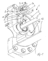
- FIG. 1 an inventive compressor 1 is shown in a longitudinal section.
- the compressor has a crankshaft housing 2, in which a crankshaft 3 is rotatably mounted.
- a compressor cylinder 4 is arranged, in which a compressor piston 5 is arranged.
- a compressor chamber 14 is formed between the compressor cylinder 4 and the compressor piston.
- the compressor piston 5 has a connecting rod 6, by means of which the compressor piston 5 is in operative connection with the crankshaft 3.
- a cylinder head 7 is arranged, in which an inlet channel 9 and an outlet channel 10 is formed.
- an inlet valve 11 is arranged in the inlet channel 9, an inlet valve 11 is arranged in the inlet channel 9, an inlet valve 11 is arranged.
- the exhaust passage 10 is provided with an exhaust valve 12.
- the compressor 1 is surrounded by a pressure capsule 13, which is formed by a surrounding the compressor 1 housing.
- the pressure capsule 13 is acted upon by the output pressure generated by the compressor and has the function of a buffer tank.
- the crankshaft housing 2 is provided with a connecting channel 15, for example a connecting bore, which establishes a connection of the pressure capsule 13 with the interior of the crankshaft housing 2. In this way it is achieved that the piston bottom 22 of the compressor piston 5 is acted upon by the pending in the pressure capsule 13 output pressure of the compressor 1.
- the compressor piston 5 is inventively designed as a rotary piston 16 which has a piston head 17 on which the connecting rod 6 is integrally formed.
- the connecting rod 6 is attached to a connecting rod 18, for example by means of a screw which is rotatably supported by a rolling bearing 19 on the crankshaft 3.
- the crankshaft 3 is in this case designed as an eccentric shaft with an eccentric 20 arranged on the crankshaft 3, on which the roller bearing 19 and thus the connecting rod eye 18 are arranged.
- the compressor piston 5 is provided with a sealing device 26 which bears against the cylinder wall 27 of the compressor cylinder 4.
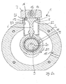
- FIG. 2a the compressor 1 is shown at top dead center.
- the crankshaft 3 in the direction 21 enters the in the FIG. 2b shown intake stroke in which flows through the inlet channel 9 to be compressed medium in the compressor chamber 14 formed between the compressor piston 5 and the compressor cylinder 4.
- the compressor 1 passes over the in the Figure 2c shown bottom dead center in the in the Figure 2d illustrated compressor cycle in the compressed medium is conveyed into the outlet channel 10.
- the trained as a rotary piston 16 compressor piston 5 performs this in the intake stroke and compressor stroke a pendulum movement.
- the swivel piston 6 is shown in the region of the piston crown 17.
- the pivot piston 16 is provided in the region of the piston head 6 with a circumferentially arranged groove-shaped recess 25 in which the sealing device 26 is arranged.
- the sealing device 26 is in this case provided with a, the cylinder wall 27 of the compressor cylinder 4 facing the convex outer surface 28.
- a spring device 29 is further arranged by means of which the sealing device 26 is pressed against the cylinder wall 27.
- the spring device 29 is hierbei- as in FIG. 5 is shown - formed as a wave spring 30 with a wavy shape.
- the cylinder head 7 is shown in a longitudinal section.
- the cylinder head 7 is provided with the intake passage 9 and the exhaust passage 10 and faces Connecting bores 35 for connecting the inlet channel 9 and the outlet channel 10 with the displacement chamber 14.
- the inlet channel 9 is provided with a diameter constriction 36, which forms a restrictor 37 for the inflowing medium.
- a diameter constriction 36 which forms a restrictor 37 for the inflowing medium.
Landscapes
- Engineering & Computer Science (AREA)
- Mechanical Engineering (AREA)
- General Engineering & Computer Science (AREA)
- Compressor (AREA)
- Compressors, Vaccum Pumps And Other Relevant Systems (AREA)
Description
- Die Erfindung betrifft einen Verdichter für kryogene Medien mit zumindest einem Verdichterzylinder, in dem ein als Schwenkkolben ausgebildeter Verdichterkolben angeordnet ist, wobei der Verdichterkolben mittels einer Pleuelstange mit einer Kurbelwelle in Wirkverbindung steht und die Kurbelwelle als eine in einem Kurbelwellengehäuse angeordnete Exzenterwelle ausgebildet ist.
- Ein gattungsgemäßer Verdichter für kryogene Medien, wie beispielsweise Stickstoff, Erdgas oder Wasserstoff in jeweils flüssigem oder gasförmigem Zustand, ist aus der
US-A-5 584 675 bekannt. Verdichter, die einen als Schwenkkolben ausgebildeten Verdichterkolben aufweisen, ermöglichen im Vergleich zu Verdichtern, bei denen der Verdichterkolben eine Linearbewegung in dem Verdichterzylinder ausführt, bei geringem Herstellaufwand einen sicheren Betrieb und weisen zu dem eine höhere Lebensdauer auf. - Der vorliegenden Erfindung liegt die Aufgabe zugrunde, einen Verdichter der eingangs genannten Gattung zur Verfügung zu stellen, der eine gegenüber den aus dem Stand der Technik bekannten Verdichtern verbesserte Konstruktion aufweist.
- Diese Aufgabe wird erfindungsgemäß dadurch gelöst, dass das Kurbelwellengehäuse mit einem Pufferbehälter in Verbindung steht, der von dem von dem Verdichter erzeugten Ausgangsdruck beaufschlagt ist. Hierdurch wird erzielt, dass die Unterseite des Kolbenbodens, die gegenüberliegend zu der in dem von dem Verdichterzylinder und dem Verdichterkolben gebildeten Verdichterraum angeordneten Kolbenoberseite angeordnet ist, von dem von dem Verdichter erzeugten Ausgangsdruck beaufschlagt ist, wodurch die Pleuelstange im Verdichtertakt lediglich geringe Druckkräfte übertragen muss und entsprechend klein dimensioniert werden kann.
- Besondere Vorteile ergeben sich, wenn der Schwenkkolben gemäß einer Ausgestaltungsform der Erfindung einen Kolbenboden aufweist, wobei die Pleuelstange mit dem Kolbenboden starr verbunden ist. Die Pleuelstange kann beispielsweise an dem Kolbenboden einstückig ausgebildet sein. Durch die starre Verbindung des Kolbenbodens mit der Pleuelstange, beispielsweise eine an dem Kolbenboden angeformte Pleuelstange, wird ein einfacher Aufbau mit geringem Herstellaufwand erzielt.
- Zweckmäßigerweise ist die Pleuelstange mit einem an der Exzenterwelle drehbar angeordneten Pleuelauge verbunden. Die Pleuelstange kann beispielsweise mittels einer Schraubverbindung mit dem Pleuelauge verbunden werden, wobei das Pleuelauge mittels eines Wälzlagers an der Exzenterwelle drehbar angeordnet ist. Hierdurch kann mit geringem Bauaufwand der Schwenkkolben mit der Exzenterwelle verbunden werden.
- Gemäß einer bevorzugten Weiterbildung der Erfindung ist der Schwenkkolben zur Abdichtung gegenüber dem Verdichterzylinder mit zumindest einer Dichtungseinrichtung versehen.
- Die Dichtungseinrichtung ist gemäß einer vorteilhaften Ausgestaltungsform mit einer balligen Außenfläche versehen. Mit einer balligen Außenfläche der Dichtungseinrichtung wird auf einfache Weise und bei geringen Reibungsverlusten eine Abdichtung zwischen dem Verdichterkolben und der Zylinderwand des Verdichterzylinders bei der von dem Verdichterkolben ausgeführten Pendelbewegung erzielt.
- Gemäß einer vorteilhaften Weiterbildung der Erfindung ist vorgesehen, dass die Dichtungseinrichtung mit einer Federeinrichtung in Wirkverbindung steht. Mit einer Federeinrichtung kann die Druckkraft der Dichtungseinrichtung an die Zylinderwand des Verdichterzylinders auf einfache Weise erhöht werden, wodurch eine sichere Abdichtung erzielt wird.
- Die Federeinrichtung ist zweckmäßigerweise als Wellenfeder ausgebildet.
- Gemäß einer vorteilhaften Ausgestaltungsform der Erfindung ist der Schwenkkolben mit einer an dem Kolbenboden in Umfangsrichtung angeordneten, nutförmigen Ausnehmung versehen, in der die Dichtungseinrichtung angeordnet ist. In einer derartigen nutförmigen Ausnehmung kann die Dichtungseinrichtung auf einfache Weise angeordnet werden.
- In dieser nutförmigen Ausnehmung kann ebenfalls die Federeinrichtung auf einfache Weise angeordnet werden.
- Besondere Vorteile sind erzielbar, wenn gemäß einer Ausgestaltungsform der Erfindung der Pufferbehälter von einer den Verdichter aufnehmenden Druckkapsel gebildet ist. Durch die Anordnung des Verdichters in einer Druckkapsel wird erzielt, dass Leckagen und Undichtigkeiten des Verdichters nicht an die Umgebung abgegeben werden, sondern in der Druckkapsel gespeichert werden. Zudem kann die Druckkapsel die Funktion eines Pufferbehälters übernehmen, wodurch ein separater Pufferbehälter, beispielsweise zusätzliche Pufferflaschen, entfallen können. Zudem kann durch die die Funktion des Pufferbehälters aufweisende Druckkapsel mittels einer einfachen Verbindungsbohrung im Kurbelwellengehäuse erzielt werden, dass das Kurbelwellengehäuse und somit die Kolbenunterseite mit dem Ausgangsdruck des Verdichters beaufschlagt ist.
- Gemäß einer vorteilhaften Weiterbildung der Erfindung ist vorgesehen, dass der Verdichter einen Zylinderkopf aufweist, in dem ein Einlasskanal und ein Auslasskanal ausgebildet ist, wobei dem Einlasskanal ein Einlassventil und dem Auslasskanal ein Auslassventil zugeordnet ist und der Einlasskanal mit einer Drosseleinrichtung versehen ist. Mit einer derartigen, dem Einlasskanal zugeordneten Drosseleinrichtung, beispielsweise einer im Zylinderkopf ausgebildeten Drosselbohrung des Einlasskanals, wird auf einfache Weise erzielt, dass an der von der Drosselbohrung gebildeten Drosselstelle ein Druckabfall auftritt. Bei zuströmendem flüssigen Medium ist dieser Druckabfall aufgrund der höheren Dichte des Mediums groß, wodurch das Medium in den gasförmigen Zustand übergeht. Bei zuströmendem gasförmigen Medium ist der auftretende Druckabfall entsprechend gering. Mit der Drosselstelle wird somit erzielt, dass sowohl bei zuströmendem flüssigen Medium als auch bei zuströmendem gasförmigen Medium eine nahezu konstante Eingangsdichte und Eingangstemperaturen des Verdichters gehalten werden kann.
- Weitere Vorteile und Einzelheiten werden anhand des in den schematischen Figuren dargestellten Ausführungsbeispiels näher erläutert. Hierbei zeigt
- Figur 1
- einen erfindungsgemäßen Verdichter in einem perspektivischen Längsschnitt,
- Figur 2a
- den Verdichter im oberen Totpunkt,
- Figur 2b
- den Verdichter im Ansaugtakt,
- Figur 2c
- den Verdichter im unteren Totpunkt
- Figur 2d
- den Verdichter im Verdichtertakt,
- Figur 3
- den Verdichterkolben in einer Teilansicht,
- Figur 4
- den Schnitt durch den Zylinderkopf und
- Figur 5
- die Wellenfeder in einer Draufsicht.
- In der
Figur 1 ist ein erfindungsgemäßer Verdichter 1 in einem Längsschnitt dargestellt. Der Verdichter weist ein Kurbelwellengehäuse 2 auf, in dem eine Kurbelwelle 3 drehbar gelagert ist. An dem Kurbelwellengehäuse 2 ist ein Verdichterzylinder 4 angeordnet, in dem ein Verdichterkolben 5 angeordnet ist. Zwischen dem Verdichterzylinder 4 und dem Verdichterkolben ist ein Verdichterraum 14 ausgebildet. - Der Verdichterkolben 5 weist eine Pleuelstange 6 auf, mittels der der Verdichterkolben 5 mit der Kurbelwelle 3 in Wirkverbindung steht. An dem Verdichterzylinder 4 ist ein Zylinderkopf 7 angeordnet, in dem ein Einlasskanal 9 und ein Auslasskanal 10 ausgebildet ist. In dem Einlasskanal 9 ist ein Einlassventil 11 angeordnet. Der Auslasskanal 10 ist mit einem Auslassventil 12 versehen.
- Der Verdichter 1 ist von einer Druckkapsel 13 umgeben, die von einem den Verdichter 1 umgebenden Gehäuse gebildet ist. Die Druckkapsel 13 ist dem von dem Verdichter erzeugten Ausgangsdruck beaufschlagt und weist die Funktion eines Pufferbehälters auf. Das Kurbelwellengehäuse 2 ist mit einem Verbindungskanal 15, beispielsweise eine Verbindungsbohrung, versehen, die eine Verbindung der Druckkapsel 13 mit dem Innenraum des Kurbelwellengehäuses 2 herstellt. Hierdurch wird erzielt, dass die Kolbenunterseite 22 des Verdichterkolbens 5 von dem in der Druckkapsel 13 anstehenden Ausgangsdruck des Verdichters 1 beaufschlagt ist.
- Wie aus den
Figuren 2a bis 2d gezeigt ist, ist der Verdichterkolben 5 erfindungsgemäß als Schwenkkolben 16 ausgebildet, der einen Kolbenboden 17 aufweist, an dem die Pleuelstange 6 einstückig angeformt ist. Die Pleuelstange 6 ist an einem Pleuelauge 18 befestigt, beispielsweise mittels einer Schraubverbindung, das mittels eines Wälzlagers 19 an der Kurbelwelle 3 drehbar gelagert ist. Die Kurbelwelle 3 ist hierbei als Exzenterwelle mit einem an der Kurbelwelle 3 angeordneten Exzenter 20 ausgebildet, an dem das Wälzlager 19 und somit das Pleuelauge 18 angeordnet ist. Der Verdichterkolben 5 ist mit einer Dichtungseinrichtung 26 versehen, die an der Zylinderwand 27 des Verdichterzylinders 4 anliegt. - In der
Figur 2a ist der Verdichter 1 im oberen Totpunkt dargestellt. Bei einer Drehung der Kurbelwelle 3 in Richtung 21 gelangt in den in derFigur 2b dargestellten Ansaugtakt, in dem über den Einlasskanal 9 zu verdichtendes Medium in den zwischen dem Verdichterkolben 5 und dem Verdichterzylinder 4 gebildeten Verdichterraum 14 einströmt. Bei weiterer Drehung der Kurbelwelle 3 in Richtung 21 gelangt der Verdichter 1 über den in derFigur 2c dargestellten unteren Totpunkt in den in derFigur 2d dargestellten Verdichtertakt, in dem verdichtetes Medium in den Auslasskanal 10 gefördert wird. Durch die Verbindung des Innenraums des Kurbelwellengehäuses 2 mit der Druckkapsel 13 mittels des Verbindungskanals 15 wird erzielt, dass die Kolbenunterseite 22 des Schwenkkolbens 16 von dem in der Druckkapsel 13 anstehenden Ausgangsdruck beaufschlagt ist, wodurch die Pleuelstange 6 im Verdichtertakt lediglich geringe Druckkräfte übertragen muss. - Der als Schwenkkolben 16 ausgebildete Verdichterkolben 5 führt hierbei im Ansaugtakt und Verdichtertakt eine Pendelbewegung aus.
- In der
Figur 3 ist der Schwenkkolben 6 im Bereich des Kolbenbodens 17 dargestellt. Der Schwenkkolben 16 ist im Bereich des Kolbenbodens 6 mit einer in Umfangsrichtung angeordneten nutförmigen Ausnehmung 25 versehen, in der die Dichtungseinrichtung 26 angeordnet ist. Die Dichtungseinrichtung 26 ist hierbei mit einer, der Zylinderwand 27 des Verdichterzylinders 4 zugewandten balligen Außenfläche 28 versehen. In der Ausnehmung 25 ist weiterhin eine Federeinrichtung 29 angeordnet mittels der die Dichtungseinrichtung 26 an die Zylinderwand 27 gepresst wird. Mit einer Dichtungseinrichtung 26 mit einer balligen Außenfläche, mittels der die Dichtungseinrichtung 26 an der Zylinderwand 27 des Verdichterzylinders 4 anliegt, wird auf einfache Weise und mit geringen Reibungsverlusten eine Abdichtung des Verdichterraums 14 bei der von dem Schwenkkolben 16 durchgeführten Pendelbewegung erzielt. - Die Federeinrichtung 29 ist hierbei- wie in
Figur 5 dargestellt ist - als Wellenfeder 30 mit einer wellenförmigen Gestalt ausgebildet. - In der
Figur 4 ist der Zylinderkopf 7 in einem Längsschnitt dargestellt. Der Zylinderkopf 7 ist mit dem Einlasskanal 9 und dem Auslasskanal 10 versehen und weist Verbindungsbohrungen 35 zur Verbindung des Einlasskanal 9 bzw. des Auslasskanals 10 mit dem Verdrängerraum 14 auf. - Der Einlasskanal 9 ist mit einer Durchmesserverengung 36 versehen, die eine Drosseleinrichtung 37 für das einströmende Medium bildet. Mit dieser Drosseleinrichtung 37 wird erzielt, dass der Verdichter 1 sowohl bei gasförmigem Medium als auch bei flüssigem Medium mit nahezu konstanter Eingangsdichte und Eingangstemperatur des zu verdichtenden Mediums betrieben werden kann.
Claims (10)
- Verdichter (1) für kryogene Medien mit zumindest einem Verdichterzylinder (4), in dem ein als Schwenkkolben (16) ausgebildeter Verdichterkolben (5) angeordnet ist, wobei der Verdichterkolben (5) mittels einer Pleuelstange (6) mit einer Kurbelwelle (3) in Wirkverbindung steht und die Kurbelwelle (3) als eine in einem Kurbelwellengehäuse (2) angeordnete Exzenterwelle ausgebildet ist, dadurch gekennzeichnet, dass das Kurbelwellengehäuse (2) mit einem Pufferbehälter in Verbindung steht, der von dem von dem Verdichter (1) erzeugten Ausgangsdruck beaufschlagt ist.
- Verdichter nach Anspruch 1, dadurch gekennzeichnet, dass der Pufferbehälter von einer den Verdichter (1) aufnehmenden Druckkapsel (13) gebildet ist.
- Verdichter nach Anspruch 1 oder 2, dadurch gekennzeichnet, dass der Schwenkkolben (16) einen Kolbenboden (17) aufweist, wobei die Pleuelstange (6) mit dem Kolbenboden (17) starr verbunden ist.
- Verdichter nach Anspruch 3, dadurch gekennzeichnet, dass die Pleuelstange (6) mit einem an der Exzenterwelle drehbar angeordneten Pleuelauge (18) verbunden ist.
- Verdichter nach einem der Ansprüche 1 bis 4 dadurch gekennzeichnet, dass der Schwenkkolben (16) zur Abdichtung gegenüber dem Verdichterzylinder (4) mit zumindest einer Dichtungseinrichtung (26) versehen ist.
- Verdichter nach Anspruch 5, dadurch gekennzeichnet, dass die Dichtungseinrichtung (26) mit einer balligen Außenfläche (28) versehen ist.
- Verdichter nach Anspruch 5 oder 6, dadurch gekennzeichnet, dass die Dichtungseinrichtung (26) mit einer Federeinrichtung (29) in Wirkverbindung steht.
- Verdichter nach Anspruch 7, dadurch gekennzeichnet, dass die Federeinrichtung (29) als Wellenfeder (30) ausgebildet.
- Verdichter nach einem der Ansprüche 5 bis 8, dadurch gekennzeichnet, dass der Schwenkkolben (16) mit einer an dem Kolbenboden (17) in Umfangsrichtung angeordneten, nutförmigen Ausnehmung (25) versehen ist, in der die Dichtungseinrichtung (26) angeordnet ist.
- Verdichter nach einem der Ansprüche 1 bis 9, dadurch gekennzeichnet, dass der Verdichter (1) einen Zylinderkopf (4) aufweist, in dem ein Einlasskanal (9) und ein Auslasskanal (10) ausgebildet ist, wobei dem Einlasskanal (9) ein Einlassventil (11) und dem Auslasskanal (10) ein Auslassventil (12) zugeordnet ist und der Einlasskanal (9) mit einer Drosseleinrichtung (37) versehen ist.
Applications Claiming Priority (2)
| Application Number | Priority Date | Filing Date | Title |
|---|---|---|---|
| DE102006011560A DE102006011560A1 (de) | 2006-03-10 | 2006-03-10 | Verdichter mit Schwenkkolben |
| PCT/EP2007/001251 WO2007104399A1 (de) | 2006-03-10 | 2007-02-13 | Verdichter mit schwenkkolben |
Publications (2)
| Publication Number | Publication Date |
|---|---|
| EP1994283A1 EP1994283A1 (de) | 2008-11-26 |
| EP1994283B1 true EP1994283B1 (de) | 2009-10-21 |
Family
ID=37950625
Family Applications (1)
| Application Number | Title | Priority Date | Filing Date |
|---|---|---|---|
| EP07703444A Not-in-force EP1994283B1 (de) | 2006-03-10 | 2007-02-13 | Verdichter mit schwenkkolben |
Country Status (5)
| Country | Link |
|---|---|
| US (1) | US20090136373A1 (de) |
| EP (1) | EP1994283B1 (de) |
| AT (1) | ATE446448T1 (de) |
| DE (2) | DE102006011560A1 (de) |
| WO (1) | WO2007104399A1 (de) |
Families Citing this family (9)
| Publication number | Priority date | Publication date | Assignee | Title |
|---|---|---|---|---|
| CN102548686B (zh) | 2009-09-22 | 2016-08-03 | Ksm铸造集团有限公司 | 真空压铸设备以及运行真空压铸设备的方法 |
| DE102010011050A1 (de) | 2009-10-20 | 2011-04-21 | Linde Aktiengesellschaft | Verdichter in Schwenkkolbenbauweise |
| ITMO20100060A1 (it) | 2010-03-10 | 2011-09-11 | Giovanni Morselli | Macchina per modificare la pressione di aria o aeriformi. |
| JP5381891B2 (ja) * | 2010-05-11 | 2014-01-08 | マックス株式会社 | ロッキングピストンのシール構造 |
| DE102012007291A1 (de) | 2012-04-12 | 2013-10-17 | Linde Aktiengesellschaft | Verdichter für tiefkalte Gase oder Flüssigkeiten |
| CN108266376B (zh) * | 2017-12-19 | 2024-05-24 | 珠海格力节能环保制冷技术研究中心有限公司 | 泵体组件、流体机械及换热设备 |
| JP7554044B2 (ja) * | 2019-10-01 | 2024-09-19 | 株式会社日立産機システム | 圧縮機 |
| JP2023134865A (ja) * | 2022-03-15 | 2023-09-28 | 株式会社日立産機システム | 圧縮機 |
| EP4711647A1 (de) * | 2024-09-13 | 2026-03-18 | KB Intellectual Property GmbH & Co. KG | Taumelkolbenring, taumelkolben und hubkolbenmaschine |
Family Cites Families (9)
| Publication number | Priority date | Publication date | Assignee | Title |
|---|---|---|---|---|
| GB683852A (en) * | 1949-12-08 | 1952-12-03 | S E P A Soc D Expl Des Procede | Improvements in compressors, particularly for refrigerating purposes |
| DE1193632B (de) * | 1962-12-11 | 1965-05-26 | Bosch Gmbh Robert | Kolben fuer Tauchkolben-Verdichter, insbesondere zu Druckluftanlagen in Kraftfahrzeugen |
| JPH0631615B2 (ja) * | 1986-12-16 | 1994-04-27 | 三菱電機株式会社 | ガス圧縮機 |
| JPH07293446A (ja) * | 1994-04-28 | 1995-11-07 | Zexel Corp | エアコンプレッサ |
| US5584675A (en) * | 1995-09-15 | 1996-12-17 | Devilbiss Air Power Company | Cylinder sleeve for an air compressor |
| GB2310464A (en) * | 1996-02-20 | 1997-08-27 | Henry John Levington | Improvements relating to vacuum pumps |
| DE29717654U1 (de) * | 1997-10-02 | 1998-11-12 | Alusuisse Bayrisches Druckguß-Werk GmbH & Co. KG, 85570 Markt Schwaben | Kolben für einen Kolbenverdichter |
| US6634870B2 (en) * | 2002-01-03 | 2003-10-21 | Tecumseh Products Company | Hermetic compressor having improved motor cooling |
| AT414269B (de) * | 2002-07-24 | 2006-10-15 | Ventrex Automotive Gmbh | Einrichtung zur verdichtung von gasen |
-
2006
- 2006-03-10 DE DE102006011560A patent/DE102006011560A1/de not_active Withdrawn
-
2007
- 2007-02-13 WO PCT/EP2007/001251 patent/WO2007104399A1/de not_active Ceased
- 2007-02-13 US US12/280,709 patent/US20090136373A1/en not_active Abandoned
- 2007-02-13 DE DE502007001801T patent/DE502007001801D1/de active Active
- 2007-02-13 EP EP07703444A patent/EP1994283B1/de not_active Not-in-force
- 2007-02-13 AT AT07703444T patent/ATE446448T1/de active
Also Published As
| Publication number | Publication date |
|---|---|
| DE502007001801D1 (de) | 2009-12-03 |
| WO2007104399A1 (de) | 2007-09-20 |
| ATE446448T1 (de) | 2009-11-15 |
| DE102006011560A1 (de) | 2007-09-13 |
| US20090136373A1 (en) | 2009-05-28 |
| EP1994283A1 (de) | 2008-11-26 |
Similar Documents
| Publication | Publication Date | Title |
|---|---|---|
| EP1994283A1 (de) | Verdichter mit schwenkkolben | |
| EP1394413B1 (de) | Hubkolbenverdichter für gasförmige Medien mit verringerter Bauhöhe | |
| EP2912310B1 (de) | Kolben-membranpumpe | |
| DE2909228A1 (de) | Maschine, insbesondere arbeitsmaschine zum verdichten und foerdern von fluiden aller art | |
| EP1775444B1 (de) | Kolbenarbeitsmaschine | |
| DE102012204264A1 (de) | Hochdruckpumpe | |
| DE102012202720A1 (de) | Hochdruckpumpe | |
| EP1377728B1 (de) | Schwenkkolbenverdränger | |
| DE102008062483A1 (de) | Axialkolbenmaschine mit Pulsationsminderung | |
| WO2007137941A1 (de) | Radialkolbenpumpe zur kraftstoff-hochdruckversorgung bei einer brennkraftmaschine | |
| EP2111498A1 (de) | Regelbare kühlmittelpumpe | |
| DE102006016791A1 (de) | Vakuumpumpe | |
| EP1682749B1 (de) | Kreiskolben-wärmemotor-vorrichtung | |
| EP2176519B1 (de) | Pendelschieber-vakuumpumpe | |
| DE102006009354A1 (de) | Zentrifugalverdichter | |
| DE102004019626B4 (de) | Kraftstoffeinspritzpumpe und Dreh-/Linearbewegungsumwandlungsmechanismus mit Sicherungseinrichtung | |
| WO2009071384A1 (de) | Kompressoreinheit | |
| DE202017007696U1 (de) | Pleuel für eine Brennkraftmaschine mit variabler Verdichtung | |
| EP2850318B1 (de) | Hochdruckpumpe | |
| DE10335603A1 (de) | Hochdruckpumpe für eine Kraftstoffeinspritzeinrichtung einer Brennkraftmaschine | |
| DE102012220832A1 (de) | Flügelzellenpumpe | |
| DE102006054744A1 (de) | Hydraulischer Zugmittelspanner mit integrierter Spannkraftbegrenzung | |
| EP0471887A1 (de) | Kolbenmaschine mit formschlüssigen Kraftübertragungsteilen | |
| WO2025149534A1 (de) | Wärmepumpe | |
| CN207316064U (zh) | 一种轻量化活塞轴 |
Legal Events
| Date | Code | Title | Description |
|---|---|---|---|
| PUAI | Public reference made under article 153(3) epc to a published international application that has entered the european phase |
Free format text: ORIGINAL CODE: 0009012 |
|
| 17P | Request for examination filed |
Effective date: 20080821 |
|
| AK | Designated contracting states |
Kind code of ref document: A1 Designated state(s): AT BE BG CH CY CZ DE DK EE ES FI FR GB GR HU IE IS IT LI LT LU LV MC NL PL PT RO SE SI SK TR |
|
| 17Q | First examination report despatched |
Effective date: 20081219 |
|
| GRAP | Despatch of communication of intention to grant a patent |
Free format text: ORIGINAL CODE: EPIDOSNIGR1 |
|
| RAP1 | Party data changed (applicant data changed or rights of an application transferred) |
Owner name: LINDE AG |
|
| GRAS | Grant fee paid |
Free format text: ORIGINAL CODE: EPIDOSNIGR3 |
|
| GRAA | (expected) grant |
Free format text: ORIGINAL CODE: 0009210 |
|
| AK | Designated contracting states |
Kind code of ref document: B1 Designated state(s): AT BE BG CH CY CZ DE DK EE ES FI FR GB GR HU IE IS IT LI LT LU LV MC NL PL PT RO SE SI SK TR |
|
| REG | Reference to a national code |
Ref country code: GB Ref legal event code: FG4D Free format text: NOT ENGLISH |
|
| REG | Reference to a national code |
Ref country code: CH Ref legal event code: EP |
|
| REG | Reference to a national code |
Ref country code: IE Ref legal event code: FG4D |
|
| REF | Corresponds to: |
Ref document number: 502007001801 Country of ref document: DE Date of ref document: 20091203 Kind code of ref document: P |
|
| REG | Reference to a national code |
Ref country code: SE Ref legal event code: TRGR |
|
| LTIE | Lt: invalidation of european patent or patent extension |
Effective date: 20091021 |
|
| NLV1 | Nl: lapsed or annulled due to failure to fulfill the requirements of art. 29p and 29m of the patents act | ||
| PG25 | Lapsed in a contracting state [announced via postgrant information from national office to epo] |
Ref country code: IS Free format text: LAPSE BECAUSE OF FAILURE TO SUBMIT A TRANSLATION OF THE DESCRIPTION OR TO PAY THE FEE WITHIN THE PRESCRIBED TIME-LIMIT Effective date: 20100221 Ref country code: LT Free format text: LAPSE BECAUSE OF FAILURE TO SUBMIT A TRANSLATION OF THE DESCRIPTION OR TO PAY THE FEE WITHIN THE PRESCRIBED TIME-LIMIT Effective date: 20091021 Ref country code: ES Free format text: LAPSE BECAUSE OF FAILURE TO SUBMIT A TRANSLATION OF THE DESCRIPTION OR TO PAY THE FEE WITHIN THE PRESCRIBED TIME-LIMIT Effective date: 20100201 Ref country code: PT Free format text: LAPSE BECAUSE OF FAILURE TO SUBMIT A TRANSLATION OF THE DESCRIPTION OR TO PAY THE FEE WITHIN THE PRESCRIBED TIME-LIMIT Effective date: 20100222 Ref country code: FI Free format text: LAPSE BECAUSE OF FAILURE TO SUBMIT A TRANSLATION OF THE DESCRIPTION OR TO PAY THE FEE WITHIN THE PRESCRIBED TIME-LIMIT Effective date: 20091021 |
|
| PG25 | Lapsed in a contracting state [announced via postgrant information from national office to epo] |
Ref country code: SI Free format text: LAPSE BECAUSE OF FAILURE TO SUBMIT A TRANSLATION OF THE DESCRIPTION OR TO PAY THE FEE WITHIN THE PRESCRIBED TIME-LIMIT Effective date: 20091021 Ref country code: CY Free format text: LAPSE BECAUSE OF FAILURE TO SUBMIT A TRANSLATION OF THE DESCRIPTION OR TO PAY THE FEE WITHIN THE PRESCRIBED TIME-LIMIT Effective date: 20091021 Ref country code: PL Free format text: LAPSE BECAUSE OF FAILURE TO SUBMIT A TRANSLATION OF THE DESCRIPTION OR TO PAY THE FEE WITHIN THE PRESCRIBED TIME-LIMIT Effective date: 20091021 Ref country code: LV Free format text: LAPSE BECAUSE OF FAILURE TO SUBMIT A TRANSLATION OF THE DESCRIPTION OR TO PAY THE FEE WITHIN THE PRESCRIBED TIME-LIMIT Effective date: 20091021 |
|
| PG25 | Lapsed in a contracting state [announced via postgrant information from national office to epo] |
Ref country code: DK Free format text: LAPSE BECAUSE OF FAILURE TO SUBMIT A TRANSLATION OF THE DESCRIPTION OR TO PAY THE FEE WITHIN THE PRESCRIBED TIME-LIMIT Effective date: 20091021 Ref country code: EE Free format text: LAPSE BECAUSE OF FAILURE TO SUBMIT A TRANSLATION OF THE DESCRIPTION OR TO PAY THE FEE WITHIN THE PRESCRIBED TIME-LIMIT Effective date: 20091021 Ref country code: RO Free format text: LAPSE BECAUSE OF FAILURE TO SUBMIT A TRANSLATION OF THE DESCRIPTION OR TO PAY THE FEE WITHIN THE PRESCRIBED TIME-LIMIT Effective date: 20091021 Ref country code: BG Free format text: LAPSE BECAUSE OF FAILURE TO SUBMIT A TRANSLATION OF THE DESCRIPTION OR TO PAY THE FEE WITHIN THE PRESCRIBED TIME-LIMIT Effective date: 20100121 |
|
| PLBE | No opposition filed within time limit |
Free format text: ORIGINAL CODE: 0009261 |
|
| STAA | Information on the status of an ep patent application or granted ep patent |
Free format text: STATUS: NO OPPOSITION FILED WITHIN TIME LIMIT |
|
| BERE | Be: lapsed |
Owner name: LINDE A.G. Effective date: 20100228 |
|
| PG25 | Lapsed in a contracting state [announced via postgrant information from national office to epo] |
Ref country code: CZ Free format text: LAPSE BECAUSE OF FAILURE TO SUBMIT A TRANSLATION OF THE DESCRIPTION OR TO PAY THE FEE WITHIN THE PRESCRIBED TIME-LIMIT Effective date: 20091021 Ref country code: SK Free format text: LAPSE BECAUSE OF FAILURE TO SUBMIT A TRANSLATION OF THE DESCRIPTION OR TO PAY THE FEE WITHIN THE PRESCRIBED TIME-LIMIT Effective date: 20091021 |
|
| 26N | No opposition filed |
Effective date: 20100722 |
|
| PG25 | Lapsed in a contracting state [announced via postgrant information from national office to epo] |
Ref country code: GR Free format text: LAPSE BECAUSE OF FAILURE TO SUBMIT A TRANSLATION OF THE DESCRIPTION OR TO PAY THE FEE WITHIN THE PRESCRIBED TIME-LIMIT Effective date: 20100122 Ref country code: MC Free format text: LAPSE BECAUSE OF NON-PAYMENT OF DUE FEES Effective date: 20100301 |
|
| PG25 | Lapsed in a contracting state [announced via postgrant information from national office to epo] |
Ref country code: BE Free format text: LAPSE BECAUSE OF NON-PAYMENT OF DUE FEES Effective date: 20100228 |
|
| PGRI | Patent reinstated in contracting state [announced from national office to epo] |
Ref country code: IT Effective date: 20110501 |
|
| PGRI | Patent reinstated in contracting state [announced from national office to epo] |
Ref country code: IT Effective date: 20110501 |
|
| PG25 | Lapsed in a contracting state [announced via postgrant information from national office to epo] |
Ref country code: NL Free format text: LAPSE BECAUSE OF FAILURE TO SUBMIT A TRANSLATION OF THE DESCRIPTION OR TO PAY THE FEE WITHIN THE PRESCRIBED TIME-LIMIT Effective date: 20091021 Ref country code: HU Free format text: LAPSE BECAUSE OF FAILURE TO SUBMIT A TRANSLATION OF THE DESCRIPTION OR TO PAY THE FEE WITHIN THE PRESCRIBED TIME-LIMIT Effective date: 20100422 Ref country code: LU Free format text: LAPSE BECAUSE OF NON-PAYMENT OF DUE FEES Effective date: 20100213 |
|
| PG25 | Lapsed in a contracting state [announced via postgrant information from national office to epo] |
Ref country code: TR Free format text: LAPSE BECAUSE OF FAILURE TO SUBMIT A TRANSLATION OF THE DESCRIPTION OR TO PAY THE FEE WITHIN THE PRESCRIBED TIME-LIMIT Effective date: 20091021 |
|
| PGFP | Annual fee paid to national office [announced via postgrant information from national office to epo] |
Ref country code: IE Payment date: 20130212 Year of fee payment: 7 |
|
| REG | Reference to a national code |
Ref country code: IE Ref legal event code: MM4A |
|
| PG25 | Lapsed in a contracting state [announced via postgrant information from national office to epo] |
Ref country code: IE Free format text: LAPSE BECAUSE OF NON-PAYMENT OF DUE FEES Effective date: 20140213 |
|
| REG | Reference to a national code |
Ref country code: FR Ref legal event code: PLFP Year of fee payment: 10 |
|
| REG | Reference to a national code |
Ref country code: FR Ref legal event code: PLFP Year of fee payment: 11 |
|
| PGFP | Annual fee paid to national office [announced via postgrant information from national office to epo] |
Ref country code: FR Payment date: 20170112 Year of fee payment: 11 Ref country code: CH Payment date: 20170214 Year of fee payment: 11 Ref country code: SE Payment date: 20170213 Year of fee payment: 11 Ref country code: DE Payment date: 20170207 Year of fee payment: 11 |
|
| PGFP | Annual fee paid to national office [announced via postgrant information from national office to epo] |
Ref country code: GB Payment date: 20170208 Year of fee payment: 11 Ref country code: AT Payment date: 20170125 Year of fee payment: 11 |
|
| PGFP | Annual fee paid to national office [announced via postgrant information from national office to epo] |
Ref country code: IT Payment date: 20170221 Year of fee payment: 11 |
|
| REG | Reference to a national code |
Ref country code: DE Ref legal event code: R119 Ref document number: 502007001801 Country of ref document: DE |
|
| REG | Reference to a national code |
Ref country code: CH Ref legal event code: PL |
|
| REG | Reference to a national code |
Ref country code: SE Ref legal event code: EUG |
|
| REG | Reference to a national code |
Ref country code: AT Ref legal event code: MM01 Ref document number: 446448 Country of ref document: AT Kind code of ref document: T Effective date: 20180213 |
|
| GBPC | Gb: european patent ceased through non-payment of renewal fee |
Effective date: 20180213 |
|
| PG25 | Lapsed in a contracting state [announced via postgrant information from national office to epo] |
Ref country code: SE Free format text: LAPSE BECAUSE OF NON-PAYMENT OF DUE FEES Effective date: 20180214 |
|
| PG25 | Lapsed in a contracting state [announced via postgrant information from national office to epo] |
Ref country code: CH Free format text: LAPSE BECAUSE OF NON-PAYMENT OF DUE FEES Effective date: 20180228 Ref country code: LI Free format text: LAPSE BECAUSE OF NON-PAYMENT OF DUE FEES Effective date: 20180228 Ref country code: AT Free format text: LAPSE BECAUSE OF NON-PAYMENT OF DUE FEES Effective date: 20180213 |
|
| REG | Reference to a national code |
Ref country code: FR Ref legal event code: ST Effective date: 20181031 |
|
| PG25 | Lapsed in a contracting state [announced via postgrant information from national office to epo] |
Ref country code: DE Free format text: LAPSE BECAUSE OF NON-PAYMENT OF DUE FEES Effective date: 20180901 |
|
| PG25 | Lapsed in a contracting state [announced via postgrant information from national office to epo] |
Ref country code: FR Free format text: LAPSE BECAUSE OF NON-PAYMENT OF DUE FEES Effective date: 20180228 Ref country code: GB Free format text: LAPSE BECAUSE OF NON-PAYMENT OF DUE FEES Effective date: 20180213 Ref country code: IT Free format text: LAPSE BECAUSE OF NON-PAYMENT OF DUE FEES Effective date: 20180213 |