EP1994294B1 - Ensemble d'etancheite annulaire, en particulier pour des moyeux de roue - Google Patents
Ensemble d'etancheite annulaire, en particulier pour des moyeux de roue Download PDFInfo
- Publication number
- EP1994294B1 EP1994294B1 EP06745238A EP06745238A EP1994294B1 EP 1994294 B1 EP1994294 B1 EP 1994294B1 EP 06745238 A EP06745238 A EP 06745238A EP 06745238 A EP06745238 A EP 06745238A EP 1994294 B1 EP1994294 B1 EP 1994294B1
- Authority
- EP
- European Patent Office
- Prior art keywords
- lip
- sealing
- shield
- annular
- radial
- Prior art date
- Legal status (The legal status is an assumption and is not a legal conclusion. Google has not performed a legal analysis and makes no representation as to the accuracy of the status listed.)
- Expired - Lifetime
Links
Images

Classifications
-
- F—MECHANICAL ENGINEERING; LIGHTING; HEATING; WEAPONS; BLASTING
- F16—ENGINEERING ELEMENTS AND UNITS; GENERAL MEASURES FOR PRODUCING AND MAINTAINING EFFECTIVE FUNCTIONING OF MACHINES OR INSTALLATIONS; THERMAL INSULATION IN GENERAL
- F16J—PISTONS; CYLINDERS; SEALINGS
- F16J15/00—Sealings
- F16J15/16—Sealings between relatively-moving surfaces
- F16J15/32—Sealings between relatively-moving surfaces with elastic sealings, e.g. O-rings
- F16J15/3248—Sealings between relatively-moving surfaces with elastic sealings, e.g. O-rings provided with casings or supports
- F16J15/3252—Sealings between relatively-moving surfaces with elastic sealings, e.g. O-rings provided with casings or supports with rigid casings or supports
- F16J15/3256—Sealings between relatively-moving surfaces with elastic sealings, e.g. O-rings provided with casings or supports with rigid casings or supports comprising two casing or support elements, one attached to each surface, e.g. cartridge or cassette seals
-
- F—MECHANICAL ENGINEERING; LIGHTING; HEATING; WEAPONS; BLASTING
- F16—ENGINEERING ELEMENTS AND UNITS; GENERAL MEASURES FOR PRODUCING AND MAINTAINING EFFECTIVE FUNCTIONING OF MACHINES OR INSTALLATIONS; THERMAL INSULATION IN GENERAL
- F16C—SHAFTS; FLEXIBLE SHAFTS; ELEMENTS OR CRANKSHAFT MECHANISMS; ROTARY BODIES OTHER THAN GEARING ELEMENTS; BEARINGS
- F16C33/00—Parts of bearings; Special methods for making bearings or parts thereof
- F16C33/72—Sealings
- F16C33/76—Sealings of ball or roller bearings
-
- F—MECHANICAL ENGINEERING; LIGHTING; HEATING; WEAPONS; BLASTING
- F16—ENGINEERING ELEMENTS AND UNITS; GENERAL MEASURES FOR PRODUCING AND MAINTAINING EFFECTIVE FUNCTIONING OF MACHINES OR INSTALLATIONS; THERMAL INSULATION IN GENERAL
- F16C—SHAFTS; FLEXIBLE SHAFTS; ELEMENTS OR CRANKSHAFT MECHANISMS; ROTARY BODIES OTHER THAN GEARING ELEMENTS; BEARINGS
- F16C19/00—Bearings with rolling contact, for exclusively rotary movement
-
- F—MECHANICAL ENGINEERING; LIGHTING; HEATING; WEAPONS; BLASTING
- F16—ENGINEERING ELEMENTS AND UNITS; GENERAL MEASURES FOR PRODUCING AND MAINTAINING EFFECTIVE FUNCTIONING OF MACHINES OR INSTALLATIONS; THERMAL INSULATION IN GENERAL
- F16C—SHAFTS; FLEXIBLE SHAFTS; ELEMENTS OR CRANKSHAFT MECHANISMS; ROTARY BODIES OTHER THAN GEARING ELEMENTS; BEARINGS
- F16C33/00—Parts of bearings; Special methods for making bearings or parts thereof
- F16C33/72—Sealings
- F16C33/76—Sealings of ball or roller bearings
- F16C33/78—Sealings of ball or roller bearings with a diaphragm, disc, or ring, with or without resilient members
-
- F—MECHANICAL ENGINEERING; LIGHTING; HEATING; WEAPONS; BLASTING
- F16—ENGINEERING ELEMENTS AND UNITS; GENERAL MEASURES FOR PRODUCING AND MAINTAINING EFFECTIVE FUNCTIONING OF MACHINES OR INSTALLATIONS; THERMAL INSULATION IN GENERAL
- F16C—SHAFTS; FLEXIBLE SHAFTS; ELEMENTS OR CRANKSHAFT MECHANISMS; ROTARY BODIES OTHER THAN GEARING ELEMENTS; BEARINGS
- F16C33/00—Parts of bearings; Special methods for making bearings or parts thereof
- F16C33/72—Sealings
- F16C33/76—Sealings of ball or roller bearings
- F16C33/78—Sealings of ball or roller bearings with a diaphragm, disc, or ring, with or without resilient members
- F16C33/7869—Sealings of ball or roller bearings with a diaphragm, disc, or ring, with or without resilient members mounted with a cylindrical portion to the inner surface of the outer race and having a radial portion extending inward
- F16C33/7879—Sealings of ball or roller bearings with a diaphragm, disc, or ring, with or without resilient members mounted with a cylindrical portion to the inner surface of the outer race and having a radial portion extending inward with a further sealing ring
-
- F—MECHANICAL ENGINEERING; LIGHTING; HEATING; WEAPONS; BLASTING
- F16—ENGINEERING ELEMENTS AND UNITS; GENERAL MEASURES FOR PRODUCING AND MAINTAINING EFFECTIVE FUNCTIONING OF MACHINES OR INSTALLATIONS; THERMAL INSULATION IN GENERAL
- F16C—SHAFTS; FLEXIBLE SHAFTS; ELEMENTS OR CRANKSHAFT MECHANISMS; ROTARY BODIES OTHER THAN GEARING ELEMENTS; BEARINGS
- F16C35/00—Rigid support of bearing units; Housings, e.g. caps, covers
-
- F—MECHANICAL ENGINEERING; LIGHTING; HEATING; WEAPONS; BLASTING
- F16—ENGINEERING ELEMENTS AND UNITS; GENERAL MEASURES FOR PRODUCING AND MAINTAINING EFFECTIVE FUNCTIONING OF MACHINES OR INSTALLATIONS; THERMAL INSULATION IN GENERAL
- F16C—SHAFTS; FLEXIBLE SHAFTS; ELEMENTS OR CRANKSHAFT MECHANISMS; ROTARY BODIES OTHER THAN GEARING ELEMENTS; BEARINGS
- F16C41/00—Other accessories, e.g. devices integrated in the bearing not relating to the bearing function as such
- F16C41/007—Encoders, e.g. parts with a plurality of alternating magnetic poles
-
- F—MECHANICAL ENGINEERING; LIGHTING; HEATING; WEAPONS; BLASTING
- F16—ENGINEERING ELEMENTS AND UNITS; GENERAL MEASURES FOR PRODUCING AND MAINTAINING EFFECTIVE FUNCTIONING OF MACHINES OR INSTALLATIONS; THERMAL INSULATION IN GENERAL
- F16C—SHAFTS; FLEXIBLE SHAFTS; ELEMENTS OR CRANKSHAFT MECHANISMS; ROTARY BODIES OTHER THAN GEARING ELEMENTS; BEARINGS
- F16C19/00—Bearings with rolling contact, for exclusively rotary movement
- F16C19/02—Bearings with rolling contact, for exclusively rotary movement with bearing balls essentially of the same size in one or more circular rows
- F16C19/04—Bearings with rolling contact, for exclusively rotary movement with bearing balls essentially of the same size in one or more circular rows for radial load mainly
- F16C19/06—Bearings with rolling contact, for exclusively rotary movement with bearing balls essentially of the same size in one or more circular rows for radial load mainly with a single row or balls
-
- F—MECHANICAL ENGINEERING; LIGHTING; HEATING; WEAPONS; BLASTING
- F16—ENGINEERING ELEMENTS AND UNITS; GENERAL MEASURES FOR PRODUCING AND MAINTAINING EFFECTIVE FUNCTIONING OF MACHINES OR INSTALLATIONS; THERMAL INSULATION IN GENERAL
- F16C—SHAFTS; FLEXIBLE SHAFTS; ELEMENTS OR CRANKSHAFT MECHANISMS; ROTARY BODIES OTHER THAN GEARING ELEMENTS; BEARINGS
- F16C2326/00—Articles relating to transporting
- F16C2326/01—Parts of vehicles in general
- F16C2326/02—Wheel hubs or castors
Definitions
- the present invention relates to an annular seal assembly of the type intended to protect the rolling bearings of a wheel hub from external contaminants, such as water, dust, mud, with which the wheel hub is constantly in contact during the operative life.
- the sealing assembly of the invention is suitable for advantageously equipping a hub bearing unit of a known type, whose hub and spindle functions are performed by the rings of a rolling bearing, which are appropriately flanged so as to receive on one side a wheel of a vehicle and on the other be fastened to the upright of a vehicle suspension.
- the rolling bearings in particular those present in wheel hubs, and more in particular those forming the hub bearing unit of the aforesaid type, are continuously exposed, in use, to the contact with high quantities of contaminants: therefore, in such applications, the sealing assemblies used to protect the bearings (incorporated in the bearings themselves or, more frequently, belonging to the hub-bearing unit) in addition to the purpose of withholding the lubricant oil or grease within the bearing, above all have the purpose of preventing external contaminants from entering inside the wheel hub and/or the bearing.
- the sealing assemblies known for the described applications present a main radial sealing lip and, more outwards, a dust lip for preserving the main lip from the contact with contaminants.
- the anti-dust lips are usually designed so as to fit with the sealing surface on which the main lip cooperates by interference, with very low interference or even with minor clearance.
- the lubricant grease possibly placed between the two lips is easily lost outwards and the external contaminants, also if in minimum amount, may come into contact with the main sealing lip and cause consequent wear of the same.
- a solution of the problem consists in shaping the anti-dust lip so as to "pump" the contaminants outwards.
- such solution is no longer satisfying in view of the longer life required by the members.
- a sealing assembly insertable between two relatively rotating members to fluid-tightly seal a compartment defined between said members from an external environment to the compartment itself, as defined in claim 1.
- the sealing assembly comprises a first annular shield presenting an axial sleeve portion for the mounting angularly integral with one of said members, and a flange portion which radially extends from a first end of the sleeve portion; and a sealing member made of elastomeric material presenting an annular root portion which overhangingly and radially extends from a peripheral edge of the flange portion and a first axially sealing annular lip, as well as a second radially sealing annular lip, said lips overhangingly and axially extending on the opposite side of the first end of the sleeve portion, from a same side as a thinned end of the root portion and being reciprocally and divergingly arranged to form in radial section a V-shape having a vertex facing towards the root portion and an axis parallel to the sleeve portion.
- the lips present respective V-shaped sealing edges and the first lip also presents a radial seat facing the opposite side of the second lip and accommodating a toroidal spring applying on the first lip an offset radial stress to an elastic hinge defined by the thinned end of the root portion and having centre of rotation arranged on a line crossing the sealing edge of the first lip and forming with a radial plane an angle ⁇ in the range from 20° to 60°.
- sealing lips may be slidingly coupled with respective sealing surfaces of a second and third annular shields selectively arrangeable coaxial with the first shield and having similar dimensions, so that both the second and the third shield can be coupled to a same said first shield.
- the centre of application of said offset radial stress on the first lip is offset also with respect to said V-shaped sealing edge of the first lip, being arranged, with respect to the same, radially displaced closer to the sleeve portion of the first shield.
- the external contaminants can reach the first lip, which forms the main sealing lip, only very difficultly and after a relative long working time because they are withheld by the second lip; furthermore, the wear of the latter does not have direct consequences on the sealing capacity of the sealing assembly entirely remitted to the first lip, also because the first lip, thanks to its particular geometry, is capable of maintaining a constant and unaltered sealing action also facing relatively high wear of the same.
- the first lip of the sealing assembly of the invention makes, given some differences related to the specific application for which it is intended, a seal similar, according to the characteristics of the sealing edge, to that which can be obtained in sealing assemblies made according to the teachings of EP0980999 , which, however, are intended for an entirely different application, i.e. for assembly between a diesel or petrol engine vehicle crankshaft and the crankcase and/or the oil sump, for withholding the oil, i.e. for application in a "clean" environment and at relative high speeds.
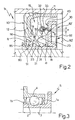
- number 1 indicates a sealing assembly insertable in a compartment 2 defined between two relatively rotating members 3,4, in particular the inner 3 and outer 4 rings of a hub bearing unit 5 ( figure 3 ) for vehicles, to isolate the compartment 2 from the outside environment.
- the sealing assembly 1 comprises a first annular shield 10 presenting an axial sleeve portion 11 for angularly and integrally mounting with one of said members, in the case in point with the outer ring 4, and a flange portion 12 which radially extends from a first end 13 of the sleeve portion 11.
- the sealing assembly 1 further comprises a sealing member 15 integrally carried by the shield 10 and made of elastomeric material (for example a natural or synthetic rubber) presenting an annular root portion 16 which radially and overhangingly protrudes from a peripheral edge 18 of the flange portion 10, a first axial sealing annular lip 20 and a second radial sealing axial lip 21.
- a sealing member 15 integrally carried by the shield 10 and made of elastomeric material (for example a natural or synthetic rubber) presenting an annular root portion 16 which radially and overhangingly protrudes from a peripheral edge 18 of the flange portion 10, a first axial sealing annular lip 20 and a second radial sealing axial lip 21.
- Lips 20 and 21 axially and overhangingly extend on the opposite side of end 13 of the sleeve portion 11, from a same side as a thinned end 23 of the root portion 16 and are reciprocally and divergingly arranged to form in radial section a V-shape having a vertex facing towards the root portion 16 and an axis parallel to the sleeve portion 11.
- Each of the lips 20,21 presents respective V-shaped sealing edges 30,31 and lip 20 also presents a radial seat 32 facing the opposite side of lip 21 and accommodating a toroidal spring 33 mounted so as to apply on lip 20 a radial stress, indicated by the arrow in figures 1 and 2 , offset to an elastic hinge defined by the thinned end 23 of the root portion 16 and having centre of rotation R arranged on a line T crossing the sealing edge 30 of lip 20 (indicated by a dash-dotted line in figure 1 ) and forming with a radial plane an angle ⁇ in the range from 20° to 60°.
- the sealing lips 20,21 are slidingly engageable, by means of V-shaped edges 30, 31, with respective sealing surfaces 40, 41 of either a second annular shield 80 ( figure 1 ) or a third annular shield 80' ( figure 2 ), both selectively, arrangeable coaxial with the shield 10 and having similar dimensions.
- the lips 20,21 are delimited towards the thinned end 23 of the annular root portion 16, and on the opposite side, by respective annular grooves 50,51 having semicircular profile in radial section, which equally delimit and define the thinned end 23; the centre of rotation R of the elastic hinge defined by such tapered end 23 of the annular root portion 16 is chosen so as to be found at the intersection of opposite lines tangent to the profile of the grooves 50,51, schematically indicated in figure 2 by broken lines.
- the sealing member 15 further presents a third lip 60, shaped as an anti-dust lip, which extends in direction opposite to lip 20 and on the same side as lip 21, overhangingly from the root portion 16; the latter extending also overhangingly and obliquely with respect to the flange portion 12, from the edge 18, in the same direction as the second lip 21 so that, in radial direction, the root portion 16 and the lips 20, 21 and 60 essentially form an X-shape, having the centre of rotation R for the lip 20 essentially arranged in the middle of the X-shape.
- the first shield 10 may be coupled, according to an aspect of the invention, either with a second annular shield 80, forming a sealing assembly of configuration 1a ( figure 1 ), or with a third annular shield 80' forming a sealing assembly of configuration 1b ( figure 2 ).
- Both shields 80 and 80' each present in radial section an essentially L-shape comprising a sleeve portion 81 for an assembly angularly integral with the other of said members, in the case in point the inner ring 3, and a flange portion 82,82', arranged in use facing and opposite the respective sleeve 11 and flange 12 portions of the first shield 10.
- the sleeve portion 81 of the shield 80,80' presents on the opposite side of the respective flange portion 82,82', an edge 85 folded towards the flange portion 12 of the first shield 10, shaped so as to form in use a centrifuge element or flinger of contaminants possibly present in the environment outside the space 2 and dimensioned so as to shield the third anti-dust lip 60 towards said outer environment, so as to protect it.
- the flange portion 82 of the second shield 80 includes, on the side opposite the first shield 10, an essentially flat metallic armature 90 carrying a magnetic elastomeric ring 91 defining a phonic wheel.
- the flange portion 82' of the third shield 80' is defined by a coined metallic armature 92 presenting a U-shaped fold at the sleeve portion 81 and a L-shaped fold at its peripheral edge, so as to present the same axial dimensions as the flange portion 82 of the second shield 80, so that the second and third shields can both either be coupled to the same first shield 10.
Landscapes
- Engineering & Computer Science (AREA)
- General Engineering & Computer Science (AREA)
- Mechanical Engineering (AREA)
- Sealing With Elastic Sealing Lips (AREA)
- Sealing Of Bearings (AREA)
- Sealing Devices (AREA)
- Gasket Seals (AREA)
Claims (9)
- Ensemble d'étanchéité (1) pouvant être inséré dans un compartiment (2) défini entre deux organes (3, 4) tournant l'un par rapport à l'autre, en particulier les bagues d'une unité de support de moyeu (5) pour des véhicules, afin d'isoler le compartiment de l'environnement extérieur, l'ensemble d'étanchéité comprenant une première plaque de protection annulaire (10) présentant une portion de manchon axial (11) pour l'assemblage angulaire et intégral à l'un (4) desdits organes, et une portion de bride (12) qui s'étend radialement depuis une première extrémité (13) de la portion de manchon (11) ; et un organe d'étanchéité (15) fabriqué en un matériau élastomère, présentant une portion de base annulaire (16) qui s'étend radialement et en porte-à-faux depuis un bord périphérique (18) de la portion de bride (12) et une première lèvre d'étanchéité annulaire axiale (20) ; ledit organe d'étanchéité (15) présentant également une deuxième lèvre d'étanchéité radiale (21), lesdites lèvres (20, 21) s'étendant axialement et en porte-à-faux sur le côté opposé de la première (13) extrémité de la portion de manchon (11), depuis un même côté qu'une extrémité amincie (23) de la portion de base (16), et étant agencées de manière réciproque et divergente de manière à former une forme en V en section radiale, ayant un sommet tourné vers la portion de base ;
lesdites lèvres (20, 21) présentant des bords d'étanchéité respectifs en forme de V (30, 31) et la première lèvre (20) présentant en outre un siège radial (32) tourné vers le côté opposé de la deuxième lèvre (21) et recevant un ressort toroïdal (33) appliquant sur la première lèvre (20) une contrainte radiale décalée sur une charnière élastique définie par l'extrémité amincie (23) de la portion de base (16) et ayant un centre de rotation (R) situé sur une ligne (T) coupant le bord d'étanchéité (30) de la première lèvre (20) et formant avec un plan radial un angle γ de l'ordre de 20° à 60° ; caractérisé en ce que, en combinaison : (i) ladite forme en V définie en section radiale par lesdites première (20) et deuxième (21) lèvres d'étanchéité a un axe parallèle à la portion de manchon (11) ; et (ii) à la fois la première et la deuxième lèvre d'étanchéité (20, 21) sont conçues pour s'accoupler, par coulissement, au moyen desdits bords en forme de V, par rapport à des surfaces d'étanchéité (40, 41) d'une deuxième (80) ou troisième (80') plaque de protection annulaire pouvant être agencée de manière sélective coaxialement à la première plaque de protection (10) et ayant des dimensions similaires ; (iii) le centre d'application de ladite contrainte radiale décalée sur la première lèvre (20) est décalé également par rapport audit bord d'étanchéité en forme de V (30) de la première lèvre (20). - Ensemble d'étanchéité (1) selon la revendication 1, caractérisé en ce que ledit centre d'application de ladite contrainte radiale décalée sur la première lèvre (20) est situé, par rapport audit bord d'étanchéité en forme de V (30) de la première lèvre (20), de manière décalée radialement plus près de la portion de manchon (11) de la première plaque de protection (10).
- Ensemble d'étanchéité (1) selon la revendication 1 ou 2, caractérisé en ce que lesdites première et deuxième lèvres annulaires (20, 21) sont définies, vers ladite extrémité amincie (23) de la portion de base annulaire (16) et sur le côté opposé, par des gorges annulaires respectives (50, 51) ayant un profil semi-circulaire dans la direction radiale, le centre de rotation de ladite charnière élastique défini par ladite extrémité amincie (23) de la portion de base annulaire (16) étant situé à l'intersection de lignes opposées tangentes au profil desdites gorges (50, 51).
- Ensemble d'étanchéité (1) selon l'une des revendications précédentes, caractérisé en ce que ledit organe d'étanchéité (15) présente une troisième lèvre (60), formée comme une lèvre antipoussière, qui s'étend dans la direction opposée à ladite première lèvre (20) et du même côté que ladite deuxième lèvre (21), en porte-à-faux depuis ladite portion de base (16) ; cette dernière s'étendant obliquement par rapport à ladite portion de bride (12), dans la même direction que la deuxième lèvre (21) de sorte que ladite portion de base (16) et lesdites première, deuxième et troisième lèvres (20, 21, 60), forment essentiellement, dans la direction radiale, une forme en X avec ledit centre de rotation pour la première lèvre (20) situé essentiellement au milieu de la forme en X.
- Ensemble d'étanchéité (1) selon la revendication 4, caractérisé en ce que lesdites deuxième (80) et troisième (80') plaques de protection annulaires présentent chacune, dans la direction radiale, une forme essentiellement en L, comprenant une portion de manchon (81) pour l'assemblage angulaire intégral avec l'autre (3) desdits organes et une portion de bride (82, 82') agencée pendant l'utilisation en face et à l'opposé desdites portions de manchon (11) et de bride (12) de ladite première plaque de protection (10) ; lesdites première et deuxième lèvres (20, 21) coopérant par coulissement avec une interférence prédéterminée respectivement avec la portion de bride (82, 82') et la portion de manchon (81) de la deuxième (80) ou de la troisième (80') plaque de protection, respectivement.
- Ensemble d'étanchéité (1) selon la revendication 5, caractérisé en ce que ladite portion de manchon (81) des deuxième et troisième plaques de protection (80, 80') présente, sur le côté opposé de la portion de bride (82, 82'), un bord (85) plié vers la portion de bride (12) de la première plaque de protection (10), formé de manière à former, pendant l'utilisation, un élément centrifuge pour des contaminants éventuels présents dans l'environnement extérieur et de manière à protéger ladite troisième lèvre (60) vers ledit environnement extérieur.
- Ensemble d'étanchéité (1) selon la revendication 5 ou 6, caractérisé en ce que ladite portion de bride (82) de la deuxième plaque de protection (80) comporte, sur le côté opposé de la première plaque de protection (10), une armature métallique essentiellement plate (90) portant une bague (91) en matériau élastomère magnétique définissant une roue phonique.
- Ensemble d'étanchéité (1) selon la revendication 7, caractérisé en ce que ladite portion de bride (82') de la troisième plaque de protection (80') est définie par une armature métallique frappée (92) présentant un pli en forme de U au niveau de la portion de manchon (81) et un pli en forme de L au niveau de son bord périphérique, de manière à présenter les mêmes dimensions axiales que la portion de bride (82) de la deuxième plaque de protection (80), de sorte que les deuxième et troisième plaques de protection (80, 80') puissent être, l'une et l'autre, accouplées à une même dite première plaque de protection (10).
- Unité de support (5), en particulier pour le moyeu d'une roue d'un véhicule automobile, comprenant un ensemble d'étanchéité (1) selon l'une quelconque des revendications précédentes.
Applications Claiming Priority (1)
| Application Number | Priority Date | Filing Date | Title |
|---|---|---|---|
| PCT/IT2006/000171 WO2007108018A1 (fr) | 2006-03-20 | 2006-03-20 | Ensemble d'étanchéité annulaire, en particulier pour des moyeux de roue |
Publications (2)
| Publication Number | Publication Date |
|---|---|
| EP1994294A1 EP1994294A1 (fr) | 2008-11-26 |
| EP1994294B1 true EP1994294B1 (fr) | 2010-05-05 |
Family
ID=37496569
Family Applications (1)
| Application Number | Title | Priority Date | Filing Date |
|---|---|---|---|
| EP06745238A Expired - Lifetime EP1994294B1 (fr) | 2006-03-20 | 2006-03-20 | Ensemble d'etancheite annulaire, en particulier pour des moyeux de roue |
Country Status (10)
| Country | Link |
|---|---|
| US (2) | US20090108539A1 (fr) |
| EP (1) | EP1994294B1 (fr) |
| JP (1) | JP4777457B2 (fr) |
| KR (1) | KR101355715B1 (fr) |
| CN (1) | CN101449073B (fr) |
| AT (1) | ATE467058T1 (fr) |
| BR (1) | BRPI0621436A2 (fr) |
| DE (1) | DE602006014213D1 (fr) |
| ES (1) | ES2347821T3 (fr) |
| WO (1) | WO2007108018A1 (fr) |
Cited By (1)
| Publication number | Priority date | Publication date | Assignee | Title |
|---|---|---|---|---|
| WO2014005763A1 (fr) | 2012-07-06 | 2014-01-09 | Schaeffler Technologies AG & Co. KG | Bague d'étanchéité avec décharge de lèvres d'étanchéité |
Families Citing this family (17)
| Publication number | Priority date | Publication date | Assignee | Title |
|---|---|---|---|---|
| DE102009005775B4 (de) * | 2009-01-23 | 2017-05-04 | Ab Skf | Lagerabdichtungsanordnung |
| US8534674B2 (en) * | 2010-11-22 | 2013-09-17 | Aktiebolaget Skf | Unitized radial fluid seal |
| ITTO20101005A1 (it) | 2010-12-16 | 2012-06-17 | Skf Ab | Gruppo cuscinetto-mozzo per la ruota di un veicolo a motore |
| JP5192074B2 (ja) * | 2010-12-20 | 2013-05-08 | Thk株式会社 | シール部材及びこれを用いた直線運動案内装置 |
| CN102734465B (zh) * | 2011-03-31 | 2016-03-30 | 株式会社久保田 | 发动机的输入操作杆轴的密封装置 |
| DE102013109257B4 (de) * | 2013-08-27 | 2024-11-07 | Dr. Ing. H.C. F. Porsche Aktiengesellschaft | Lagerelement |
| DE102013111494A1 (de) * | 2013-10-18 | 2015-04-23 | Netzsch Pumpen & Systeme Gmbh | Dichtungs- und Lagereinheit für wenigstens zwei parallel zueinander orientierte Wellen sowie Verfahren zum Trennen einer Dichtungs- und Lagereinheit von wenigstens zwei parallel zueinander orientierten Wellen |
| DK2995829T3 (en) * | 2014-09-12 | 2017-12-11 | Skf Ab | SEALING FOR A ROLLER BEARING |
| IT201600113594A1 (it) * | 2016-11-10 | 2018-05-10 | Freudenberg Sealing Tech S A S Di Externa Italia S R L U | Gruppo di tenuta per un organo rotante |
| IT201600120099A1 (it) * | 2016-11-28 | 2018-05-28 | Skf Ab | Sistema di accoppiamento di un complesso di tenuta a basso attrito, ed unita’ mozzo ruota equipaggiata con tale complesso di tenuta |
| CN109307077B (zh) * | 2017-07-27 | 2022-11-29 | 舍弗勒技术股份两合公司 | 密封组件 |
| CN108374881A (zh) * | 2018-02-05 | 2018-08-07 | 江门市鑫辉密封科技有限公司 | 一种变速箱用耐大偏心及低摩擦阻力的轴密封组件 |
| US10934970B2 (en) * | 2018-09-10 | 2021-03-02 | Caterpillar Inc. | Crankshaft seal |
| DE102018220346A1 (de) * | 2018-11-27 | 2020-05-28 | Aktiebolaget Skf | Lagerdichtung |
| CN109510368B (zh) * | 2018-12-26 | 2024-08-16 | 金风科技股份有限公司 | 风力发电机组及其发电机、密封防护机构 |
| IT201900020112A1 (it) | 2019-10-31 | 2021-05-01 | Skf Ab | Dispositivo e sistema di tenuta dinamica ad interferenza con comportamento di contatto migliorato |
| US11384792B2 (en) * | 2020-08-31 | 2022-07-12 | Aktiebolaget Skf | Slewing bearing for food processing equipment |
Family Cites Families (17)
| Publication number | Priority date | Publication date | Assignee | Title |
|---|---|---|---|---|
| IT208052Z2 (it) * | 1986-07-08 | 1988-03-31 | Riv Officine Di Villar Perosa | Complesso di tenuta atto ad essere interposto fra due organi in moto relativo |
| JPS6336759A (ja) * | 1986-07-30 | 1988-02-17 | Chisso Corp | 被覆有機酸製剤の製造法 |
| JPS6336759U (fr) * | 1986-08-27 | 1988-03-09 | ||
| JPH0686909B2 (ja) * | 1987-11-23 | 1994-11-02 | ザ ティムケン カンパニー | 小型シール |
| IT1288742B1 (it) * | 1996-10-08 | 1998-09-24 | Skf Ind Spa | Complesso di tenuta per un cuscinetto di rotolamento. |
| IT1303234B1 (it) * | 1998-08-18 | 2000-11-02 | Rft Spa | Complesso di tenuta, in particolare per alberi motore di veicoli. |
| US6213476B1 (en) * | 1998-09-03 | 2001-04-10 | Federal-Mogul World Wide, Inc. | Bi-modulus composite seal and its method of manufacture |
| JP2000289405A (ja) * | 1999-04-02 | 2000-10-17 | Nsk Ltd | エンコーダ付組み合わせシールリング |
| US6173961B1 (en) * | 1999-04-06 | 2001-01-16 | Trw Inc. | Seal assembly |
| DE10056175A1 (de) * | 1999-11-17 | 2001-06-13 | Ntn Toyo Bearing Co Ltd | Wheel Bearing and Sealing Davice Therefor |
| JP4128723B2 (ja) * | 2000-04-10 | 2008-07-30 | Ntn株式会社 | 車輪用軸受 |
| DE10019994A1 (de) * | 2000-04-22 | 2001-10-31 | Freudenberg Carl Fa | Radialwellendichtring |
| ITTO20010245A1 (it) * | 2001-03-16 | 2002-09-16 | S K F Ind S P A | Dispositivo di tenuta per cuscinetti. |
| ITTO20010708A1 (it) * | 2001-07-19 | 2003-01-19 | Skf Ind Spa | Dispositivo di tenuta per cuscinetti. |
| JP4325152B2 (ja) * | 2002-07-05 | 2009-09-02 | 株式会社ジェイテクト | 転がり軸受の密封装置 |
| JP4297658B2 (ja) * | 2002-07-29 | 2009-07-15 | Ntn株式会社 | 車輪用軸受装置 |
| DE10246398A1 (de) * | 2002-10-04 | 2004-04-29 | Ina-Schaeffler Kg | Wellenlippendichtung |
-
2006
- 2006-03-20 EP EP06745238A patent/EP1994294B1/fr not_active Expired - Lifetime
- 2006-03-20 BR BRPI0621436-3A patent/BRPI0621436A2/pt active Search and Examination
- 2006-03-20 US US12/225,553 patent/US20090108539A1/en not_active Abandoned
- 2006-03-20 DE DE602006014213T patent/DE602006014213D1/de not_active Expired - Lifetime
- 2006-03-20 WO PCT/IT2006/000171 patent/WO2007108018A1/fr not_active Ceased
- 2006-03-20 KR KR1020087023429A patent/KR101355715B1/ko not_active Expired - Lifetime
- 2006-03-20 ES ES06745238T patent/ES2347821T3/es not_active Expired - Lifetime
- 2006-03-20 CN CN2006800546616A patent/CN101449073B/zh not_active Expired - Lifetime
- 2006-03-20 JP JP2009501023A patent/JP4777457B2/ja not_active Expired - Fee Related
- 2006-03-20 AT AT06745238T patent/ATE467058T1/de not_active IP Right Cessation
-
2011
- 2011-04-04 US US13/079,587 patent/US20110233874A1/en not_active Abandoned
Cited By (3)
| Publication number | Priority date | Publication date | Assignee | Title |
|---|---|---|---|---|
| WO2014005763A1 (fr) | 2012-07-06 | 2014-01-09 | Schaeffler Technologies AG & Co. KG | Bague d'étanchéité avec décharge de lèvres d'étanchéité |
| DE102012211853A1 (de) | 2012-07-06 | 2014-01-09 | Schaeffler Technologies AG & Co. KG | Dichtring mit Dichtlippenentlastung |
| DE102012211853B4 (de) * | 2012-07-06 | 2020-11-26 | Schaeffler Technologies AG & Co. KG | Dichtring mit Dichtlippenentkopplung, Kassettendichtung mit einem solchen Dichtring und Wälzlager mit einem solchen Dichtring oder einer solchen Kassettendichtung |
Also Published As
| Publication number | Publication date |
|---|---|
| WO2007108018A1 (fr) | 2007-09-27 |
| KR101355715B1 (ko) | 2014-01-24 |
| KR20090021142A (ko) | 2009-02-27 |
| WO2007108018A8 (fr) | 2008-03-27 |
| CN101449073A (zh) | 2009-06-03 |
| ATE467058T1 (de) | 2010-05-15 |
| ES2347821T3 (es) | 2010-11-04 |
| JP2009530564A (ja) | 2009-08-27 |
| US20110233874A1 (en) | 2011-09-29 |
| EP1994294A1 (fr) | 2008-11-26 |
| BRPI0621436A2 (pt) | 2012-07-10 |
| CN101449073B (zh) | 2011-06-29 |
| US20090108539A1 (en) | 2009-04-30 |
| JP4777457B2 (ja) | 2011-09-21 |
| DE602006014213D1 (de) | 2010-06-17 |
Similar Documents
| Publication | Publication Date | Title |
|---|---|---|
| US20110233874A1 (en) | Annular Sealing Assembly, in Particular for Wheel Hubs | |
| US9464720B2 (en) | Annular sealing assembly, in particular for wheel hubs | |
| EP2685118B1 (fr) | Ensemble de roulement et moyeu de roue pour véhicule motorisé avec joint d'étanchéité | |
| CA2350138C (fr) | Joint d'etancheite | |
| EP2962018B1 (fr) | Joint principal pour un ensemble d'extrémités de roues de véhicule lourd | |
| JP5158389B2 (ja) | 密封装置 | |
| EP3012475B1 (fr) | Unité de roulement de moyeu avec un dispositif d'étanchéité | |
| WO2009130933A1 (fr) | Dispositif d’étanchéité | |
| JP5708204B2 (ja) | シール構造 | |
| EP2685119B1 (fr) | Ensemble de roulement et moyeu de roue pour véhicule motorisé avec un joint d'étanchéité | |
| US11982356B2 (en) | Seal assembly with labyrinth channel | |
| US7314219B1 (en) | Shaft seal assembly | |
| CN112303129A (zh) | 密封装置 | |
| US12025183B2 (en) | Wheel bearing | |
| KR102592982B1 (ko) | 씰링 기능이 향상된 차량용 휠베어링 | |
| WO2010107855A1 (fr) | Joint modulaire pour unité logée dans un roulement à billes à large anneau interne | |
| CN111577768A (zh) | 密封装置 |
Legal Events
| Date | Code | Title | Description |
|---|---|---|---|
| PUAI | Public reference made under article 153(3) epc to a published international application that has entered the european phase |
Free format text: ORIGINAL CODE: 0009012 |
|
| 17P | Request for examination filed |
Effective date: 20080930 |
|
| AK | Designated contracting states |
Kind code of ref document: A1 Designated state(s): AT BE BG CH CY CZ DE DK EE ES FI FR GB GR HU IE IS IT LI LT LU LV MC NL PL PT RO SE SI SK TR |
|
| GRAP | Despatch of communication of intention to grant a patent |
Free format text: ORIGINAL CODE: EPIDOSNIGR1 |
|
| GRAS | Grant fee paid |
Free format text: ORIGINAL CODE: EPIDOSNIGR3 |
|
| GRAA | (expected) grant |
Free format text: ORIGINAL CODE: 0009210 |
|
| AK | Designated contracting states |
Kind code of ref document: B1 Designated state(s): AT BE BG CH CY CZ DE DK EE ES FI FR GB GR HU IE IS IT LI LT LU LV MC NL PL PT RO SE SI SK TR |
|
| REG | Reference to a national code |
Ref country code: GB Ref legal event code: FG4D |
|
| REG | Reference to a national code |
Ref country code: CH Ref legal event code: EP |
|
| REG | Reference to a national code |
Ref country code: IE Ref legal event code: FG4D |
|
| REF | Corresponds to: |
Ref document number: 602006014213 Country of ref document: DE Date of ref document: 20100617 Kind code of ref document: P |
|
| REG | Reference to a national code |
Ref country code: DE Ref legal event code: R096 Ref document number: 602006014213 Country of ref document: DE Effective date: 20100617 |
|
| REG | Reference to a national code |
Ref country code: SE Ref legal event code: TRGR Ref country code: NL Ref legal event code: VDEP Effective date: 20100505 |
|
| LTIE | Lt: invalidation of european patent or patent extension |
Effective date: 20100505 |
|
| PG25 | Lapsed in a contracting state [announced via postgrant information from national office to epo] |
Ref country code: LT Free format text: LAPSE BECAUSE OF FAILURE TO SUBMIT A TRANSLATION OF THE DESCRIPTION OR TO PAY THE FEE WITHIN THE PRESCRIBED TIME-LIMIT Effective date: 20100505 Ref country code: NL Free format text: LAPSE BECAUSE OF FAILURE TO SUBMIT A TRANSLATION OF THE DESCRIPTION OR TO PAY THE FEE WITHIN THE PRESCRIBED TIME-LIMIT Effective date: 20100505 |
|
| REG | Reference to a national code |
Ref country code: ES Ref legal event code: FG2A Ref document number: 2347821 Country of ref document: ES Kind code of ref document: T3 |
|
| PG25 | Lapsed in a contracting state [announced via postgrant information from national office to epo] |
Ref country code: LV Free format text: LAPSE BECAUSE OF FAILURE TO SUBMIT A TRANSLATION OF THE DESCRIPTION OR TO PAY THE FEE WITHIN THE PRESCRIBED TIME-LIMIT Effective date: 20100505 Ref country code: FI Free format text: LAPSE BECAUSE OF FAILURE TO SUBMIT A TRANSLATION OF THE DESCRIPTION OR TO PAY THE FEE WITHIN THE PRESCRIBED TIME-LIMIT Effective date: 20100505 Ref country code: SI Free format text: LAPSE BECAUSE OF FAILURE TO SUBMIT A TRANSLATION OF THE DESCRIPTION OR TO PAY THE FEE WITHIN THE PRESCRIBED TIME-LIMIT Effective date: 20100505 Ref country code: IS Free format text: LAPSE BECAUSE OF FAILURE TO SUBMIT A TRANSLATION OF THE DESCRIPTION OR TO PAY THE FEE WITHIN THE PRESCRIBED TIME-LIMIT Effective date: 20100905 Ref country code: AT Free format text: LAPSE BECAUSE OF FAILURE TO SUBMIT A TRANSLATION OF THE DESCRIPTION OR TO PAY THE FEE WITHIN THE PRESCRIBED TIME-LIMIT Effective date: 20100505 |
|
| PG25 | Lapsed in a contracting state [announced via postgrant information from national office to epo] |
Ref country code: GR Free format text: LAPSE BECAUSE OF FAILURE TO SUBMIT A TRANSLATION OF THE DESCRIPTION OR TO PAY THE FEE WITHIN THE PRESCRIBED TIME-LIMIT Effective date: 20100806 Ref country code: CY Free format text: LAPSE BECAUSE OF FAILURE TO SUBMIT A TRANSLATION OF THE DESCRIPTION OR TO PAY THE FEE WITHIN THE PRESCRIBED TIME-LIMIT Effective date: 20100602 Ref country code: PL Free format text: LAPSE BECAUSE OF FAILURE TO SUBMIT A TRANSLATION OF THE DESCRIPTION OR TO PAY THE FEE WITHIN THE PRESCRIBED TIME-LIMIT Effective date: 20100505 |
|
| PG25 | Lapsed in a contracting state [announced via postgrant information from national office to epo] |
Ref country code: EE Free format text: LAPSE BECAUSE OF FAILURE TO SUBMIT A TRANSLATION OF THE DESCRIPTION OR TO PAY THE FEE WITHIN THE PRESCRIBED TIME-LIMIT Effective date: 20100505 Ref country code: PT Free format text: LAPSE BECAUSE OF FAILURE TO SUBMIT A TRANSLATION OF THE DESCRIPTION OR TO PAY THE FEE WITHIN THE PRESCRIBED TIME-LIMIT Effective date: 20100906 Ref country code: DK Free format text: LAPSE BECAUSE OF FAILURE TO SUBMIT A TRANSLATION OF THE DESCRIPTION OR TO PAY THE FEE WITHIN THE PRESCRIBED TIME-LIMIT Effective date: 20100505 |
|
| PG25 | Lapsed in a contracting state [announced via postgrant information from national office to epo] |
Ref country code: RO Free format text: LAPSE BECAUSE OF FAILURE TO SUBMIT A TRANSLATION OF THE DESCRIPTION OR TO PAY THE FEE WITHIN THE PRESCRIBED TIME-LIMIT Effective date: 20100505 Ref country code: SK Free format text: LAPSE BECAUSE OF FAILURE TO SUBMIT A TRANSLATION OF THE DESCRIPTION OR TO PAY THE FEE WITHIN THE PRESCRIBED TIME-LIMIT Effective date: 20100505 Ref country code: BE Free format text: LAPSE BECAUSE OF FAILURE TO SUBMIT A TRANSLATION OF THE DESCRIPTION OR TO PAY THE FEE WITHIN THE PRESCRIBED TIME-LIMIT Effective date: 20100505 Ref country code: CZ Free format text: LAPSE BECAUSE OF FAILURE TO SUBMIT A TRANSLATION OF THE DESCRIPTION OR TO PAY THE FEE WITHIN THE PRESCRIBED TIME-LIMIT Effective date: 20100505 |
|
| PLBE | No opposition filed within time limit |
Free format text: ORIGINAL CODE: 0009261 |
|
| STAA | Information on the status of an ep patent application or granted ep patent |
Free format text: STATUS: NO OPPOSITION FILED WITHIN TIME LIMIT |
|
| 26N | No opposition filed |
Effective date: 20110208 |
|
| REG | Reference to a national code |
Ref country code: DE Ref legal event code: R097 Ref document number: 602006014213 Country of ref document: DE Effective date: 20110207 Ref country code: DE Ref legal event code: R097 Ref document number: 602006014213 Country of ref document: DE Effective date: 20110208 |
|
| PG25 | Lapsed in a contracting state [announced via postgrant information from national office to epo] |
Ref country code: MC Free format text: LAPSE BECAUSE OF NON-PAYMENT OF DUE FEES Effective date: 20110331 |
|
| REG | Reference to a national code |
Ref country code: CH Ref legal event code: PL |
|
| REG | Reference to a national code |
Ref country code: IE Ref legal event code: MM4A |
|
| PG25 | Lapsed in a contracting state [announced via postgrant information from national office to epo] |
Ref country code: LI Free format text: LAPSE BECAUSE OF NON-PAYMENT OF DUE FEES Effective date: 20110331 Ref country code: CH Free format text: LAPSE BECAUSE OF NON-PAYMENT OF DUE FEES Effective date: 20110331 Ref country code: IE Free format text: LAPSE BECAUSE OF NON-PAYMENT OF DUE FEES Effective date: 20110320 |
|
| PG25 | Lapsed in a contracting state [announced via postgrant information from national office to epo] |
Ref country code: LU Free format text: LAPSE BECAUSE OF NON-PAYMENT OF DUE FEES Effective date: 20110320 |
|
| PG25 | Lapsed in a contracting state [announced via postgrant information from national office to epo] |
Ref country code: TR Free format text: LAPSE BECAUSE OF FAILURE TO SUBMIT A TRANSLATION OF THE DESCRIPTION OR TO PAY THE FEE WITHIN THE PRESCRIBED TIME-LIMIT Effective date: 20100505 Ref country code: BG Free format text: LAPSE BECAUSE OF FAILURE TO SUBMIT A TRANSLATION OF THE DESCRIPTION OR TO PAY THE FEE WITHIN THE PRESCRIBED TIME-LIMIT Effective date: 20100805 |
|
| PG25 | Lapsed in a contracting state [announced via postgrant information from national office to epo] |
Ref country code: HU Free format text: LAPSE BECAUSE OF FAILURE TO SUBMIT A TRANSLATION OF THE DESCRIPTION OR TO PAY THE FEE WITHIN THE PRESCRIBED TIME-LIMIT Effective date: 20100505 |
|
| REG | Reference to a national code |
Ref country code: FR Ref legal event code: PLFP Year of fee payment: 10 |
|
| PGFP | Annual fee paid to national office [announced via postgrant information from national office to epo] |
Ref country code: ES Payment date: 20150428 Year of fee payment: 10 |
|
| PGFP | Annual fee paid to national office [announced via postgrant information from national office to epo] |
Ref country code: FR Payment date: 20150331 Year of fee payment: 10 |
|
| PGFP | Annual fee paid to national office [announced via postgrant information from national office to epo] |
Ref country code: GB Payment date: 20160331 Year of fee payment: 11 |
|
| REG | Reference to a national code |
Ref country code: FR Ref legal event code: ST Effective date: 20161130 |
|
| PG25 | Lapsed in a contracting state [announced via postgrant information from national office to epo] |
Ref country code: FR Free format text: LAPSE BECAUSE OF NON-PAYMENT OF DUE FEES Effective date: 20160331 |
|
| PG25 | Lapsed in a contracting state [announced via postgrant information from national office to epo] |
Ref country code: IT Free format text: LAPSE BECAUSE OF NON-PAYMENT OF DUE FEES Effective date: 20160320 |
|
| PG25 | Lapsed in a contracting state [announced via postgrant information from national office to epo] |
Ref country code: IT Free format text: LAPSE BECAUSE OF NON-PAYMENT OF DUE FEES Effective date: 20160320 |
|
| PGFP | Annual fee paid to national office [announced via postgrant information from national office to epo] |
Ref country code: IT Payment date: 20160325 Year of fee payment: 11 |
|
| PGRI | Patent reinstated in contracting state [announced from national office to epo] |
Ref country code: IT Effective date: 20170710 |
|
| GBPC | Gb: european patent ceased through non-payment of renewal fee |
Effective date: 20170320 |
|
| PG25 | Lapsed in a contracting state [announced via postgrant information from national office to epo] |
Ref country code: IT Free format text: LAPSE BECAUSE OF NON-PAYMENT OF DUE FEES Effective date: 20170320 Ref country code: GB Free format text: LAPSE BECAUSE OF NON-PAYMENT OF DUE FEES Effective date: 20170320 |
|
| PGRI | Patent reinstated in contracting state [announced from national office to epo] |
Ref country code: IT Effective date: 20170710 |
|
| PG25 | Lapsed in a contracting state [announced via postgrant information from national office to epo] |
Ref country code: ES Free format text: LAPSE BECAUSE OF NON-PAYMENT OF DUE FEES Effective date: 20160321 |
|
| REG | Reference to a national code |
Ref country code: ES Ref legal event code: FD2A Effective date: 20181207 |
|
| PGFP | Annual fee paid to national office [announced via postgrant information from national office to epo] |
Ref country code: SE Payment date: 20230317 Year of fee payment: 18 |
|
| P01 | Opt-out of the competence of the unified patent court (upc) registered |
Effective date: 20230513 |
|
| REG | Reference to a national code |
Ref country code: SE Ref legal event code: EUG |
|
| PGFP | Annual fee paid to national office [announced via postgrant information from national office to epo] |
Ref country code: DE Payment date: 20250327 Year of fee payment: 20 |
|
| PG25 | Lapsed in a contracting state [announced via postgrant information from national office to epo] |
Ref country code: SE Free format text: LAPSE BECAUSE OF NON-PAYMENT OF DUE FEES Effective date: 20240321 |
|
| REG | Reference to a national code |
Ref country code: DE Ref legal event code: R071 Ref document number: 602006014213 Country of ref document: DE |