EP1994316B2 - Lagerbuchsensystem für eine zweiteilige lenkwelle - Google Patents
Lagerbuchsensystem für eine zweiteilige lenkwelle Download PDFInfo
- Publication number
- EP1994316B2 EP1994316B2 EP07721875.8A EP07721875A EP1994316B2 EP 1994316 B2 EP1994316 B2 EP 1994316B2 EP 07721875 A EP07721875 A EP 07721875A EP 1994316 B2 EP1994316 B2 EP 1994316B2
- Authority
- EP
- European Patent Office
- Prior art keywords
- bearing sleeve
- sealing
- steering shaft
- sealing element
- sleeve system
- Prior art date
- Legal status (The legal status is an assumption and is not a legal conclusion. Google has not performed a legal analysis and makes no representation as to the accuracy of the status listed.)
- Not-in-force
Links
Images
Classifications
-
- F—MECHANICAL ENGINEERING; LIGHTING; HEATING; WEAPONS; BLASTING
- F16—ENGINEERING ELEMENTS AND UNITS; GENERAL MEASURES FOR PRODUCING AND MAINTAINING EFFECTIVE FUNCTIONING OF MACHINES OR INSTALLATIONS; THERMAL INSULATION IN GENERAL
- F16J—PISTONS; CYLINDERS; SEALINGS
- F16J15/00—Sealings
- F16J15/16—Sealings between relatively-moving surfaces
- F16J15/32—Sealings between relatively-moving surfaces with elastic sealings, e.g. O-rings
- F16J15/3204—Sealings between relatively-moving surfaces with elastic sealings, e.g. O-rings with at least one lip
- F16J15/3232—Sealings between relatively-moving surfaces with elastic sealings, e.g. O-rings with at least one lip having two or more lips
- F16J15/3236—Sealings between relatively-moving surfaces with elastic sealings, e.g. O-rings with at least one lip having two or more lips with at least one lip for each surface, e.g. U-cup packings
-
- B—PERFORMING OPERATIONS; TRANSPORTING
- B62—LAND VEHICLES FOR TRAVELLING OTHERWISE THAN ON RAILS
- B62D—MOTOR VEHICLES; TRAILERS
- B62D1/00—Steering controls, i.e. means for initiating a change of direction of the vehicle
- B62D1/02—Steering controls, i.e. means for initiating a change of direction of the vehicle vehicle-mounted
- B62D1/16—Steering columns
- B62D1/18—Steering columns yieldable or adjustable, e.g. tiltable
- B62D1/185—Steering columns yieldable or adjustable, e.g. tiltable adjustable by axial displacement, e.g. telescopically
-
- F—MECHANICAL ENGINEERING; LIGHTING; HEATING; WEAPONS; BLASTING
- F16—ENGINEERING ELEMENTS AND UNITS; GENERAL MEASURES FOR PRODUCING AND MAINTAINING EFFECTIVE FUNCTIONING OF MACHINES OR INSTALLATIONS; THERMAL INSULATION IN GENERAL
- F16C—SHAFTS; FLEXIBLE SHAFTS; ELEMENTS OR CRANKSHAFT MECHANISMS; ROTARY BODIES OTHER THAN GEARING ELEMENTS; BEARINGS
- F16C33/00—Parts of bearings; Special methods for making bearings or parts thereof
- F16C33/72—Sealings
- F16C33/74—Sealings of sliding-contact bearings
-
- F—MECHANICAL ENGINEERING; LIGHTING; HEATING; WEAPONS; BLASTING
- F16—ENGINEERING ELEMENTS AND UNITS; GENERAL MEASURES FOR PRODUCING AND MAINTAINING EFFECTIVE FUNCTIONING OF MACHINES OR INSTALLATIONS; THERMAL INSULATION IN GENERAL
- F16J—PISTONS; CYLINDERS; SEALINGS
- F16J15/00—Sealings
- F16J15/16—Sealings between relatively-moving surfaces
- F16J15/32—Sealings between relatively-moving surfaces with elastic sealings, e.g. O-rings
- F16J15/3248—Sealings between relatively-moving surfaces with elastic sealings, e.g. O-rings provided with casings or supports
- F16J15/3252—Sealings between relatively-moving surfaces with elastic sealings, e.g. O-rings provided with casings or supports with rigid casings or supports
-
- F—MECHANICAL ENGINEERING; LIGHTING; HEATING; WEAPONS; BLASTING
- F16—ENGINEERING ELEMENTS AND UNITS; GENERAL MEASURES FOR PRODUCING AND MAINTAINING EFFECTIVE FUNCTIONING OF MACHINES OR INSTALLATIONS; THERMAL INSULATION IN GENERAL
- F16J—PISTONS; CYLINDERS; SEALINGS
- F16J15/00—Sealings
- F16J15/56—Other sealings for reciprocating rods
-
- F—MECHANICAL ENGINEERING; LIGHTING; HEATING; WEAPONS; BLASTING
- F16—ENGINEERING ELEMENTS AND UNITS; GENERAL MEASURES FOR PRODUCING AND MAINTAINING EFFECTIVE FUNCTIONING OF MACHINES OR INSTALLATIONS; THERMAL INSULATION IN GENERAL
- F16C—SHAFTS; FLEXIBLE SHAFTS; ELEMENTS OR CRANKSHAFT MECHANISMS; ROTARY BODIES OTHER THAN GEARING ELEMENTS; BEARINGS
- F16C2326/00—Articles relating to transporting
- F16C2326/20—Land vehicles
- F16C2326/24—Steering systems, e.g. steering rods or columns
Definitions
- the invention relates to a bearing bushing system for a two-part steering shaft for the axially movable and sealing connection of an outer steering shaft to an inner steering shaft, which system comprises a bearing bushing, static and dynamic sealing means and a cover cap.
- a known two-part steering shaft for commercial vehicles comprises an outer steering shaft consisting of an outer tube with a bearing bush integrated into its free end, in which an inner steering shaft designed as an inner tube is axially movably guided in order to compensate for vibrations which occur during vehicle operation and which are transmitted to the steering shaft or to allow length compensation of the steering shaft when tilting the driver's cab.
- the bearing bushing should not only allow a slight and vibration-damping sliding movement, but also ensure a good external seal between the two concentrically arranged parts, namely against spray and washing water as well as dirt, dust and sand particles.
- U.S. 4,261,583 discloses a bearing bushing system according to the preamble of claim 1.
- a bearing bush arrangement with a Simmerring placed on the outer end face of the bearing bush, the circumferential sealing lip of which rests against the surface of the inner steering shaft, has already been proposed.
- the Simmerring is fixed with a cranked holding sleeve.
- the static seal between the bearing bushing and the steering shaft is carried out with an O-ring arranged between the holding sleeve and the end face of the outer steering shaft.
- the proposed solution is disadvantageous in that the manufacturing costs and the assembly effort for the bearing bushing, which consists of a total of four individual parts, are high.
- the O-ring can be compressed too much by the holding sleeve and thereby loses its elasticity and the sealing effect based on it.
- the invention is based on the object of developing a bearing bush for a two-part steering shaft that can be manufactured and assembled with little effort and also has an improved sliding and sealing effect.
- the basic idea of the invention consists in the positive connection of the hard plastic bearing bush, which is held on the outer steering shaft by means of a stop collar and a sealing element molded in one piece from a flexible plastic, which has both a dynamic lip seal against the inner steering shaft and a includes static sealing ring for frontal sealing on the outer steering shaft.
- a watchtower-like, interlocking rib toothing is formed on both sides, which also absorbs the pretensioning force of the holding bush and which is also clawed into one another due to the shrinkage during cooling.
- the molded-on static sealing ring extends over the height of the side surface of the stop collar and therefore has a high elastic sealing effect.
- the bearing bush which is combined in this way from two plastics and forms a single part, can be manufactured and assembled with little effort and ensures reliable static and dynamic sealing.
- the static seal comprises two sealing lips running around one another at a distance with a lubricant reservoir formed between them. This improves both the sliding properties and the dynamic sealing.
- longitudinal ribs and / or transverse ribs are formed on the outer surface of the bearing bush for stiffening.
- the one-piece sealing element consists of a thermoplastic elastomer which is supported on or in the toothed ribs of the bearing bushing, which is preferably made of polyamide, and is thus prevented from flowing.
- a lubricant for example Teflon or molybdenum dioxide, is preferably incorporated into the polyamide.
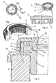
- an outer steering shaft 1 is attached to a bearing bushing 3 held on the end face of a stop collar 2 for axially moveable accommodation of an inner steering shaft (not shown).
- the bearing bush 3 consists of a hard first plastic - in the present embodiment made of polyamide - with a chemically embedded lubricant, for example Teflon or molybdenum dioxide.
- longitudinal ribs 4 with a semicircular cross section and / or transverse ribs 5 lying between these are formed at regular intervals.
- first toothed ribs 6 are formed on the end face of the stop collar 2 and the bearing bush 3.
- a sealing element 7 that overlaps the side face of the stop collar 2 is fastened in a form-fitting manner, with the aid of second toothed ribs 8 formed on the underside of the sealing element 7 and engaging in the spaces between the first toothed ribs 6.
- the sealing element 7 consists of a soft second plastic, that is, a thermoplastic elastomer (TPE, technical rubber), which shrinks when it cools on the bearing bush made of the hard plastic, so that its (second) toothed ribs 8 fit into the (first) Toothed ribs 6 of the bearing bush 3 claw and thus a firm, intimate - but not rubberized adhesive - connection between the bearing bush 3 and the sealing element 7 is established.
- TPE thermoplastic elastomer
- the pressure acting on the sealing element 7 made of soft thermoplastic elastomer is absorbed by the bearing bush 3 and the toothed ribs 6 made of hard polyamide.
- the reduced material proportion of thermoplastic elastomer due to the rib structure also provides direct support for the sealing element 7 and thus avoids its tendency to flow away at high pressure.
- the sealing element 7 has an inner leg 9 (lip sealing ring) with two sealing lips running around one another at a distance, that is, a first sealing lip 10 and a second sealing lip 11 with a lubricant reservoir 12 formed between them.
- a circumferential outer leg rests on the side surface of the stop collar 2 and, with its bulge 13 protruding slightly over the side surface of the stop collar 2 and resting on the end face of the outer steering shaft 1, forms as a whole a static sealing ring 14 with a large spring travel corresponding to the large leg length.
- This static seal retains its elastic sealing effect even at very high pressure.
- a groove 15 is formed in the sealing element 8 at the transition to this sealing lip 10.
- the bearing bush arrangement thus consists of only two easy-to-assemble components with five functions, that is, plain bearings, static sealing, dynamic sealing including lubricating effect and fastening.
- the manufacturing and assembly outlay for such a bearing bush arrangement is therefore low.
- a one-piece sealing element with excellent sealing properties against pressure or spray water, steam, dirt, dust and sand is provided.
- the two plastic components of the first component are positively connected to one another in such a way that the soft sealing material is prevented from flowing away under the action of pressure.
Landscapes
- Engineering & Computer Science (AREA)
- General Engineering & Computer Science (AREA)
- Mechanical Engineering (AREA)
- Chemical & Material Sciences (AREA)
- Combustion & Propulsion (AREA)
- Transportation (AREA)
- Sealing Of Bearings (AREA)
- Sliding-Contact Bearings (AREA)
- Sealing Devices (AREA)
- Steering Controls (AREA)
- Steering Devices For Bicycles And Motorcycles (AREA)
- Shafts, Cranks, Connecting Bars, And Related Bearings (AREA)
- Support Of The Bearing (AREA)
Description
- Die Erfindung betrifft ein Lagerbuchsensystem für eine zweiteilige Lenkwelle zur axial beweglichen und abdichtenden Verbindung einer äußeren Lenkwelle mit einer inneren Lenkwelle, das eine Lagerbuchse, statische und dynamische Dichtungsmittel und eine Abdecckappe umfasst.
- Eine bekannte zweiteilige Lenkwelle für Nutzfahrzeuge umfasst eine aus einem Außenrohr bestehende äußere Lenkwelle mit einer in deren freies Ende integrierten Lagerbuchse, in der eine als Innenrohr ausgebildete innere Lenkwelle axial beweglich geführt ist, um während des Fahrzeugbetriebes auftretende, sich auf die Lenkwelle übertragende Schwingungen zu kompensieren oder beim Kippen der Fahrerkabine einen Längenausgleich der Lenkwelle zuzulassen. Die Lagerbuchse soll nicht nur eine leichte und schwingungsdämpfende Gleitbewegung ermöglichen, sondern darüber hinaus nach außen eine gute Abdichtung zwischen den beiden konzentrisch angeordneten Teilen, und zwar gegenüber Spritz- und Waschwasser sowie Schmutz-, Staubund Sandpartikeln, gewährleisten.
-
US 4,261,583 offenbart ein Lagerbuchsensystem gemäß dem Oberbegriff des Anspruchs 1. - Zur gegenseitigen Abdichtung der beiden Lenkwellenteile wurde bereits eine Lagerbuchsenanordnung mit einem auf die außen liegende Stirnfläche der Lagerbuchse aufgesetzten Simmerring, dessen umlaufende Dichtlippe an der Oberfläche der inneren Lenkwelle anliegt, vorgeschlagen. Der Simmerring wird mit einer abgekröpften Haltehülse fixiert. Die statische Abdichtung zwischen Lagerbuchse und Lenkwelle erfolgt mit einem zwischen der Haltehülse und der Stirnfläche der äußeren Lenkwelle angeordneten O-Ring.
- Die vorgeschlagene Lösung ist insofern nachteilig, als die Herstellungskosten und der Montageaufwand für die aus insgesamt vier Einzelteilen bestehende Lagerbuchse hoch sind. Zudem kann der O-Ring durch die Haltehülse zu stark zusammengepresst werden und verliert dadurch seine Elastizität und die darauf beruhende Dichtwirkung.
- Der Erfindung liegt die Aufgabe zugrunde, eine Lagerbuchse für eine zweiteilige Lenkwelle zu entwickeln, die mit geringem Aufwand hergestellt und montiert werden kann und zudem eine verbesserte Gleit- und Dichtwirkung hat.
- Erfindungsgemäß wird die Aufgabe mit einer gemäß den Merkmalen des Patentanspruchs 1 ausgebildeten Lagerbuchse gelöst. Vorteilhafte Weiterbildungen und zweckmäßige Ausgestaltungen der Erfindung sind Gegenstand der Unteransprüche.
- Der Grundgedanke der Erfindung besteht mit anderen Worten in der formschlüssigen Verbindung der mittels eines Anschlagbundes an der äußeren Lenkwelle gehaltenen, aus einem harten Kunststoff bestehenden Lagerbuchse mit einem aus einem weichelastischen Kunststoff einstückig geformten Dichtungselement, das sowohl eine dynamische Lippendichtung gegenüber der inneren Lenkwelle als auch einen statischen Dichtungsring zur stirnseitigen Abdichtung an der äußeren Lenkwelle umfasst. Zur formschlüssigen Befestigung des Dichtungselements an der Stirnseite der Lagerbuchse ist beidseitig eine wachturmartige, ineinander greifende Rippenverzahnung ausgebildet, die auch die Vorspannkraft der Haltebuchse aufnimmt und die zudem aufgrund der Schrumpfung während des Abkühlens ineinander verkrallt ist. Der angeformte statische Dichtungsring erstreckt sich über die Höhe der Seitenfläche des Anschlagbundes und hat daher eine hohe elastische Dichtwirkung. Die derart aus zwei Kunststoffen kombinierte, ein einziges Teil bildende Lagerbuchse kann mit geringem Aufwand hergestellt und montiert werden und gewährleistet eine sichere statische und dynamische Abdichtung.
- In weiterer Ausbildung der Erfindung umfasst die statische Dichtung zwei im Abstand übereinander umlaufende Dichtungslippen mit einem zwischen diesen ausgebildeten Schmiermittelreservoir. Dadurch werden sowohl die Gleiteigenschaften als auch die dynamische Abdichtung verbessert.
- In Ausgestaltung der Erfindung sind an der Außenfläche der Lagerbuchse zur Versteifung Längsrippen und/oder Querrippen angeformt.
- Das einstückige Dichtungselement besteht aus einem thermoplastischen Elastomer, das sich auf bzw. in den Verzahnungsrippen der vorzugsweise aus Polyamid bestehenden Lagerbuchse abstützt und so am Fließen gehindert ist. Vorzugsweise ist in das Polyamid ein Gleitmittel, beispielsweise Teflon oder Molybdändioxid, eingelagert.
- Ein Ausführungsbeispiel der Erfindung, aus dem sich weitere vorteilhafte Ausgestaltungen des Lagerbuchsensystems ergeben, wird anhand der Zeichnung näher erläutert. Es zeigen:
- Fig. 1
- eine perspektivische Ansicht einer auf der äuße- ren Lenkwelle angebrachten Lagerbuchsenanordnung im Schnitt;
- Fig. 2
- eine vergrößerte Darstellung eines Teils des La- gerbuchsensystems;
- Fig. 3
- eine Seitenansicht einer Lagerbuchse mit einem an dieser selbsthaltend angebrachten statisch und dynamisch wirkenden Dichtungselement;
- Fig. 4
- eine perspektivische Darstellung des Lagerbuch- sensystems nach
Fig. 3 , jedoch mit teilweise weggeschnittenen dargestelltem Dichtungsele- ment; und - Fig. 5
- eine Unteransicht des Dichtungselements.
- Wie in
Fig. 1 und 2 dargestellt, ist im Innern einer äußeren Lenkwelle 1 eine an einem Anschlagbund 2 stirnseitig gehaltene Lagerbuchse 3 zur axial beweglichen Aufnahme einer inneren Lenkwelle (nicht dargestellt) angebracht. Die Lagerbuchse 3 besteht aus einem harten ersten Kunststoff - in der vorliegenden Ausführungsform aus Polyamid - mit einem in diesen chemisch eingelagerten Gleitmittel, beispielsweise Teflon oder Molybdändioxid. Am Außenumfang der Lagerbuchse 3 sind in regelmäßigem Abstand im Querschnitt halbkreisförmige Längsrippen 4 und/oder zwischen diesen liegende Querrippen 5 angeformt. Auf der Stirnseite des Anschlagbundes 2 und der Lagerbuchse 3 sind erste Verzahnungsrippen 6 ausgebildet. Auf der Stirnfläche der Lagerbuchse 3 ist ein auch die Seitenfläche des Anschlagbundes 2 übergreifendes Dichtungselement 7 formschlüssig befestigt, und zwar mit Hilfe von in die Räume zwischen den ersten Verzahnungsrippen 6 eingreifenden, an der Unterseite des Dichtungselements 7 angeformten zweiten Verzahnungsrippen 8. - Das Dichtungselement 7 besteht aus einem weichen zweiten Kunststoff, das heißt, einem thermoplastischen Elastomer (TPE, technischer Gummi), das beim Abkühlen auf der aus dem harten Kunststoff bestehenden Lagerbuchse schrumpft, so dass sich dessen (zweite) Verzahnungsrippen 8 in den (ersten) Verzahnungsrippen 6 der Lagerbuchse 3 verkrallen und so eine feste, innige - jedoch nicht aufgummierte klebende - Verbindung zwischen der Lagerbuchse 3 und dem Dichtungselement 7 hergestellt wird. Der auf das Dichtungselement 7 aus weichem thermoplastischem Elastomer wirkende Druck wird von der Lagerbuchse 3 und den aus hartem Polyamid bestehenden Verzahnungsrippen 6 aufgefangen. Der aufgrund der Rippenstruktur verringerte Materialanteil an thermoplastischem Elastomer bewirkt zudem eine unmittelbare Abstützung des Dichtungselements 7 und vermeidet damit dessen Neigung zum Wegfließen bei hohem Druck.
- Das Dichtungselement 7 weist einen Innenschenkel 9 (Lippendichtring) mit zwei übereinander im Abstand umlaufenden Dichtungslippen, das heißt, einer ersten Dichtungslippe 10 und einer zweiten Dichtungslippe 11 mit einem zwischen diesen gebildeten Schmiermittelreservoir 12, auf. Ein umlaufender Außenschenkel liegt an der Seitenfläche des Anschlagbundes 2 an und bildet mit seiner geringfügig über die Seitenfläche des Anschlagbundes 2 ragenden, auf der Stirnfläche der äußeren Lenkwelle 1 anliegenden Ausbauchung 13 als Ganzes einen statischen Dichtungsring 14 mit entsprechend der großen Schenkellänge großem Federweg. Selbst bei sehr hohem Druck behält diese statische Dichtung ihre elastisch abdichtende Wirkung. Zur Erhöhung der Elastizität der ersten (oberen) Dichtungslippe 11 ist in das Dichtungselement 8 am Übergang zu dieser Dichtungslippe 10 eine Nut 15 eingeformt. Die Lagerbuchse 3 und das mit dieser fest verbundene Dichtungselement 7 mit den beiden erste und zweite Dichtlippen 10, 11 bildenden dynamischen Dichtungen und dem statisch wirkenden Dichtungsring 14 bilden ein einziges, aus zwei Kunststoffen fest zusammengefügtes erstes Bauteil, das mittels einem zweiten Bauteil, nämlich einer metallischen Abdeckkappe 16, auf der Stirnseite der äußeren Lenkwelle 1 fixiert wird.
- Die Lagerbuchsenanordnung besteht somit aus lediglich zwei einfach zu montierenden Bauteilen mit fünf Funktionen, das heißt, Gleitlagerung, statische Abdichtung, dynamische Abdichtung einschließlich Schmierwirkung und Befestigung. Der Fertigungs- und Montageaufwand für eine derartige Lagerbuchsenanordnung ist daher gering. Zudem wird mit zwei Lippendichtungen und einem Schmierfettreservoir sowie mit einer hochelastischen statischen Dichtung, ein einstückiges Dichtungselement mit hervorragenden Dichtungseigenschaften gegenüber Druck- oder Spritzwasser, Dampf, Schmutz, Staub und Sand bereitgestellt.
- Darüber hinaus sind die beiden aus Kunststoff bestehenden Bestandteile des ersten Bauteils derart formschlüssig miteinander verbunden, dass ein Wegfließen des weichen Dichtungsmaterials unter Druckeinwirkung vermieden wird.
-
- 1
- äußere Lenkwelle
- 2
- Anschlagbund
- 3
- Lagerbuchse
- 4
- Längsrippen
- 5
- Querrippen
- 6
- erste Verzahnungsrippen v. 3
- 7
- Dichtungselement
- 8
- zweite Verzahnungsrippen v. 7
- 9
- Innenschenkel/dyn. Lippendichtung v. 7
- 10
- erste Dichtungslippe
- 11
- zweite Dichtungslippe
- 12
- Schmiermittelreservoir
- 13
- Ausbauchung
- 14
- statischer Dichtungsring
- 15
- Nut
- 16
- Abdeckkappe
Claims (8)
- Lagerbuchsensystem für eine zweiteilige Lenkwelle zur axial beweglichen und abdichtenden Verbindung einer äußeren Lenkwelle (1) mit einer inneren Lenkwelle, das eine Lagerbuchse (3), statische und dynamische Dichtungsmittel und eine Abdeckkappe (16) umfasst, dadurch gekennzeichnet, dass die aus einem harten Kunststoff bestehende, mit einem Anschlagbund (2) versehene Lagerbuchse (3) stirnseitig über eine formschlüssig ineinander greifende Schrumpfverzahnung (6, 8) mit einem aus weichelastischem Kunststoff bestehenden, statisch und dynamisch abdichtenden, einstückig ausgebildeten Dichtungselement (7) verbunden ist und dabei das weichelastische Material abstützt, wobei die Schrumpfverzahnung aus am Dichtungselement und an der Lagerbuchse (3) jeweils als Wachturmstruktur ausgebildeten ersten und zweiten Verzahnungsrippen (6, 8) besteht, die aufgrund einer beim Abkühlen des Kunststoffs auftretenden Schrumpfung mechanisch ineinander verkrallt sind, wobei ein zur dynamischen Abdichtung vorgesehener umlaufender Innenschenkel (9) des Dichtungselements (7) eine erste Dichtungslippe (10) aufweist und ein die Seitenfläche des Anschlagbundes (2) übergreifender umlaufender Außenschenkel des Dichtungselements (7) die äußere Lenkwelle (1) stirnseitig kontaktiert und als statischer Dichtungsring (14) fungiert.
- Lagerbuchsensystem nach Anspruch 1, dadurch gekennzeichnet, dass im Abstand von der ersten umlaufenden Dichtlippe (10) eine zweite umlaufende Dichtlippe (11) ausgebildet ist, die ein Schmiermittelreservoir (12) einschließen.
- Lagerbuchsensystem nach Anspruch 1, dadurch gekennzeichnet, dass am Übergang zu dem die Dichtungslippen bildenden Innenschenkel (9) in das Dichtungselement (7) eine umlaufende Nut (15)eingeformt ist.
- Lagerbuchsensystem nach Anspruch 1, dadurch gekennzeichnet, dass der statische Dichtungsring (14) des Dichtungselements (7) an seiner freien Stirnseite eine über die Seitenfläche des Anschlagbundes (2) hinaus ragende, die Lenkwelle (1) kontaktierende Ausbauchung (13) aufweist.
- Lagerbuchsensystem nach Anspruch 1, dadurch gekennzeichnet, dass an der Außenfläche der Lagerbuchse (1) im Querschnitt halbkreisförmige Längsrippen (4) und/oder Querrippen (5) angeformt sind.
- Lagerbuchsensystem nach Anspruch 1, dadurch gekennzeichnet, dass der für die Lagerbuchse (3) verwendete Kunststoff Polyamid mit chemisch eingelagertem Gleitmittel ist.
- Lagerbuchsensystem nach Anspruch 7, dadurch gekennzeichnet, dass das Gleitmittel Teflon oder Molybdandioxid ist.
- Lagerbuchsensystem nach Anspruch 1, dadurch gekennzeichnet, dass der für das Dichtungselement (7) eingesetzte Kunststoff ein thermoplastisches Elastomer ist.
Applications Claiming Priority (2)
| Application Number | Priority Date | Filing Date | Title |
|---|---|---|---|
| DE102006012057A DE102006012057A1 (de) | 2006-03-08 | 2006-03-08 | Lagerbuchsensystem für eine zweiteilige Lenkwelle |
| PCT/DE2007/000203 WO2007101414A1 (de) | 2006-03-08 | 2007-01-31 | Lagerbuchsensystem für eine zweiteilige lenkwelle |
Publications (3)
| Publication Number | Publication Date |
|---|---|
| EP1994316A1 EP1994316A1 (de) | 2008-11-26 |
| EP1994316B1 EP1994316B1 (de) | 2010-02-24 |
| EP1994316B2 true EP1994316B2 (de) | 2021-03-10 |
Family
ID=38017260
Family Applications (1)
| Application Number | Title | Priority Date | Filing Date |
|---|---|---|---|
| EP07721875.8A Not-in-force EP1994316B2 (de) | 2006-03-08 | 2007-01-31 | Lagerbuchsensystem für eine zweiteilige lenkwelle |
Country Status (5)
| Country | Link |
|---|---|
| US (1) | US7988362B2 (de) |
| EP (1) | EP1994316B2 (de) |
| AT (1) | ATE458943T1 (de) |
| DE (2) | DE102006012057A1 (de) |
| WO (1) | WO2007101414A1 (de) |
Families Citing this family (16)
| Publication number | Priority date | Publication date | Assignee | Title |
|---|---|---|---|---|
| DE102009000432A1 (de) * | 2009-01-27 | 2010-07-29 | Zf Lenksysteme Gmbh | Teleskopierbare Lenkwelle |
| DE102010028297B4 (de) | 2010-04-28 | 2023-08-24 | Robert Bosch Gmbh | Lagerbuchsen-Anordnung für eine teleskopartige Lenkwelle und damit ausgestattetes Lenksystem |
| ITTO20110581A1 (it) | 2011-07-01 | 2013-01-02 | Skf Ab | Complesso anulare di tenuta, in particolare per l'interposizione tra elementi soggetti a disassamento |
| ITTO20130460A1 (it) * | 2013-06-04 | 2014-12-05 | Skf Ab | Complesso di tenuta inseribile tra due organi relativamente scorrevoli |
| DE102013108421A1 (de) | 2013-08-05 | 2015-02-05 | Dr. Walter Hunger Beteiligungs GmbH & Co. Besitz KG | Abstreifereinheit sowie hydraulische Arbeitsvorrichtung mit einer Abstreifereinheit |
| EP3093429A4 (de) * | 2014-01-03 | 2017-10-25 | Liu, Suhua | Schwimmendes dichtungsverfahren einer schwimmenden buchse, hin- und hergehende abdichtende aufprallvorrichtung und schwimmende abdichtende hin- und hergehende aufprallvorrichtung einer abdichtenden schwimmenden buchse eines bergbauladers |
| DE102014209127A1 (de) * | 2014-05-14 | 2015-11-19 | Schaeffler Technologies AG & Co. KG | Dichtringträger für einen Radialwellendichtring |
| DE102014110077B4 (de) | 2014-07-17 | 2016-02-18 | Dionex Softron Gmbh | Dichtungssystem und Verfahren zu seiner Montage |
| DE102014216672A1 (de) | 2014-08-21 | 2016-02-25 | Ford Global Technologies, Llc | Lagerbuchse sowie schwingungsdämpfende Verbindungsanordnung |
| DE102014216670B4 (de) | 2014-08-21 | 2016-05-19 | Ford Global Technologies, Llc | Lagerbuchse |
| DE202014103932U1 (de) | 2014-08-21 | 2014-09-19 | Ford Global Technologies, Llc | Lagerbuchse sowie schwingungsdämpfende Verbindungsanordnung |
| DE102015008987B4 (de) * | 2014-12-12 | 2016-08-11 | Carl Freudenberg Kg | Stoßdämpfer und dessen Verwendung |
| DE102016114678A1 (de) | 2016-08-08 | 2018-02-08 | Thyssenkrupp Ag | Drehlageranordnung für eine Lenksäule eines Kraftfahrzeugs |
| US11465670B2 (en) * | 2019-04-18 | 2022-10-11 | Zf Active Safety And Electronics Us Llc | Steering shaft support assembly |
| DE102020121886A1 (de) | 2020-08-20 | 2022-02-24 | Woco Industrietechnik Gmbh | KFZ-Lenksäulenlagerung |
| CN114183472B (zh) * | 2021-12-13 | 2024-11-05 | 中冶焦耐(大连)工程技术有限公司 | 一种内置吊挂式挡油装置的轴承密封结构 |
Citations (5)
| Publication number | Priority date | Publication date | Assignee | Title |
|---|---|---|---|---|
| DE69101303T2 (de) † | 1990-11-28 | 1994-10-06 | Ecia Equip Composants Ind Auto | Elastisches Gleitlager und seine Verwendung für Automobillenkungen. |
| DE19615157A1 (de) † | 1996-04-17 | 1997-10-23 | Lucas Ind Plc | Ringförmiges Dichtelement |
| DE10010524A1 (de) † | 2000-03-07 | 2001-09-27 | Freudenberg Carl Fa | Abstreifer mit integrierter Dichtung |
| DE10329893A1 (de) † | 2003-07-03 | 2005-02-03 | Carl Freudenberg Kg | Dichtung |
| WO2006007822A1 (de) † | 2004-07-20 | 2006-01-26 | Zf Friedrichshafen Ag | Lageranordnung |
Family Cites Families (22)
| Publication number | Priority date | Publication date | Assignee | Title |
|---|---|---|---|---|
| US2512098A (en) * | 1945-10-24 | 1950-06-20 | Gratzmuller Jean Louis | Sealing packing |
| FR1357192A (fr) * | 1963-03-26 | 1964-04-03 | Simmerwerke Simmer Kg | Joint d'étanchéité radial annulaire rapporté sur un coussinet par vulcanisation ou collage |
| DE6910130U (de) | 1969-03-10 | 1969-10-16 | Fendt & Co Xaver | Anhaengerkupplung |
| DE2948248A1 (de) * | 1979-11-30 | 1981-06-04 | Bertrams Ag, 5900 Siegen | Wandelement fuer laermschutzwaende |
| US4261583A (en) | 1979-12-10 | 1981-04-14 | Vries Jr Donald S De | Unitary rod gland assembly |
| JPS58100884U (ja) * | 1981-12-28 | 1983-07-08 | 株式会社昭和製作所 | 二輪車等のフロントフオ−クのシ−ル装置 |
| DE3246349A1 (de) * | 1982-12-15 | 1984-06-20 | FAG Kugelfischer Georg Schäfer KGaA, 8720 Schweinfurt | Geberzylinder |
| DE3501334C1 (de) * | 1985-01-17 | 1986-04-10 | Fa. Carl Freudenberg, 6940 Weinheim | Dichtung |
| US4934668A (en) * | 1988-08-19 | 1990-06-19 | Chicago Rawhide Manufacturing Co. | Unitary seal for gas pressure spring assembly |
| EP0516708B1 (de) * | 1990-02-26 | 1994-12-21 | ZF FRIEDRICHSHAFEN Aktiengesellschaft | Dichtungsanordnung |
| JPH0914452A (ja) * | 1995-04-26 | 1997-01-14 | Nippon Seiko Kk | オイルシールリップの潤滑構造 |
| FR2741316B1 (fr) * | 1995-11-17 | 1998-01-02 | Nacam | Dispositif d'articulation d'une colonne de direction de vehicule automobile |
| US6203022B1 (en) | 1996-04-17 | 2001-03-20 | Lucas Industries Public Limited | Annular sealing element |
| US6065292A (en) * | 1997-03-14 | 2000-05-23 | Lucas Industries Plc | Master cylinder |
| DE19839597A1 (de) * | 1998-08-31 | 2000-03-02 | Continental Teves Ag & Co Ohg | Dichtungseinsatz, insbesondere für einen Kolben einer hydraulischen Fahrzeugbremsanlage |
| DE19917006A1 (de) * | 1999-04-15 | 2000-10-19 | Mannesmann Sachs Ag | Zylinder für eine hydraulische Anlage |
| DE10108775B4 (de) * | 2001-02-23 | 2006-04-06 | Lucas Automotive Gmbh | Hauptzylinder |
| US6681885B2 (en) * | 2001-09-19 | 2004-01-27 | Trw Inc. | Rack and pinion steering gear with powdered metal bushing |
| JP2004237760A (ja) | 2003-02-03 | 2004-08-26 | Advics:Kk | シール構造およびそのシール構造を用いた入力ロッド引張り式ブレーキ倍力装置 |
| US6896110B2 (en) | 2003-09-25 | 2005-05-24 | Tenneco Automotive Operating Company Inc. | Temperature compensated dual acting slip |
| WO2005068277A1 (ja) * | 2004-01-15 | 2005-07-28 | Nsk Ltd. | ステアリングシャフト用ダストカバー |
| JP5078338B2 (ja) * | 2006-12-12 | 2012-11-21 | ルネサスエレクトロニクス株式会社 | 半導体記憶装置 |
-
2006
- 2006-03-08 DE DE102006012057A patent/DE102006012057A1/de not_active Withdrawn
-
2007
- 2007-01-31 US US12/224,702 patent/US7988362B2/en not_active Expired - Fee Related
- 2007-01-31 DE DE502007002926T patent/DE502007002926D1/de active Active
- 2007-01-31 EP EP07721875.8A patent/EP1994316B2/de not_active Not-in-force
- 2007-01-31 AT AT07721875T patent/ATE458943T1/de active
- 2007-01-31 WO PCT/DE2007/000203 patent/WO2007101414A1/de not_active Ceased
Patent Citations (5)
| Publication number | Priority date | Publication date | Assignee | Title |
|---|---|---|---|---|
| DE69101303T2 (de) † | 1990-11-28 | 1994-10-06 | Ecia Equip Composants Ind Auto | Elastisches Gleitlager und seine Verwendung für Automobillenkungen. |
| DE19615157A1 (de) † | 1996-04-17 | 1997-10-23 | Lucas Ind Plc | Ringförmiges Dichtelement |
| DE10010524A1 (de) † | 2000-03-07 | 2001-09-27 | Freudenberg Carl Fa | Abstreifer mit integrierter Dichtung |
| DE10329893A1 (de) † | 2003-07-03 | 2005-02-03 | Carl Freudenberg Kg | Dichtung |
| WO2006007822A1 (de) † | 2004-07-20 | 2006-01-26 | Zf Friedrichshafen Ag | Lageranordnung |
Also Published As
| Publication number | Publication date |
|---|---|
| WO2007101414A1 (de) | 2007-09-13 |
| US20090028479A1 (en) | 2009-01-29 |
| DE502007002926D1 (de) | 2010-04-08 |
| ATE458943T1 (de) | 2010-03-15 |
| DE102006012057A1 (de) | 2007-09-13 |
| EP1994316B1 (de) | 2010-02-24 |
| EP1994316A1 (de) | 2008-11-26 |
| US7988362B2 (en) | 2011-08-02 |
Similar Documents
| Publication | Publication Date | Title |
|---|---|---|
| EP1994316B2 (de) | Lagerbuchsensystem für eine zweiteilige lenkwelle | |
| DE4037966C2 (de) | Elastisches Gleitlager für Fahrwerksteile | |
| DE4036051C1 (de) | ||
| EP0485696B1 (de) | Elastisches Gleitlager | |
| DE102010028297B4 (de) | Lagerbuchsen-Anordnung für eine teleskopartige Lenkwelle und damit ausgestattetes Lenksystem | |
| DE102007024628B4 (de) | Radaufhängungseinrichtung und Federbein | |
| DE102014206658B4 (de) | Federbeinlager mit einer Zweikomponenten Kappe | |
| WO2008068179A2 (de) | Federbeinlager | |
| DE2542085C2 (de) | Dichtanordnung | |
| DE4120772C2 (de) | Radial und axial belastbares Drehgleitlager für Fahrwerksteile in Kraftfahrzeugen | |
| EP1132642B1 (de) | Gummilager | |
| EP3957546A1 (de) | Kfz-lenksäulenlagerung | |
| DE69804170T2 (de) | Elastisches Lager zum Halt eines Drehstabs einer Stabilisierungsvorrichtung | |
| DE102017204818A1 (de) | Auilhängungsaxiallagereinheit | |
| DE102004031559B4 (de) | Elastomeres Buchsenlager mit verbessertem Torsionsverhalten | |
| EP1769168B1 (de) | Lageranordnung | |
| DE102015209335A1 (de) | Federbeinstützlageranordnung sowie Federbein einer Radaufhängung eines Kraftfahrzeuges | |
| DE102010035188A1 (de) | Federbeingleitlager | |
| DE19834678C2 (de) | Abgedichtetes, Schwenkbewegungen ausführendes Gelenklager | |
| DE1111957B (de) | Aus elastischem Werkstoff bestehende Lagerung zur Aufnahme von in radialer Richtung auftretenden Kraeften, vorzugsweise Lagerung fuer Torsionsfederstaebe an Kraftfahrzeugen | |
| DE102014219858B4 (de) | Kreuzgelenk | |
| WO2007085323A2 (de) | Kopfteil einer federbeinaufhängung und federbeinaufhängung | |
| DE102022207218A1 (de) | Aufhängungslagereinheit mit Versteifungseinsatz | |
| DE8235995U1 (de) | Federnder Träger für einen Stoßdämpfer einer vorderen Federung eines Fahrzeugs | |
| DE102016208720A1 (de) | Federbeinlager |
Legal Events
| Date | Code | Title | Description |
|---|---|---|---|
| PUAI | Public reference made under article 153(3) epc to a published international application that has entered the european phase |
Free format text: ORIGINAL CODE: 0009012 |
|
| 17P | Request for examination filed |
Effective date: 20081001 |
|
| AK | Designated contracting states |
Kind code of ref document: A1 Designated state(s): AT BE BG CH CY CZ DE DK EE ES FI FR GB GR HU IE IS IT LI LT LU LV MC NL PL PT RO SE SI SK TR |
|
| GRAP | Despatch of communication of intention to grant a patent |
Free format text: ORIGINAL CODE: EPIDOSNIGR1 |
|
| GRAS | Grant fee paid |
Free format text: ORIGINAL CODE: EPIDOSNIGR3 |
|
| GRAA | (expected) grant |
Free format text: ORIGINAL CODE: 0009210 |
|
| AK | Designated contracting states |
Kind code of ref document: B1 Designated state(s): AT BE BG CH CY CZ DE DK EE ES FI FR GB GR HU IE IS IT LI LT LU LV MC NL PL PT RO SE SI SK TR |
|
| REG | Reference to a national code |
Ref country code: GB Ref legal event code: FG4D Free format text: NOT ENGLISH |
|
| REG | Reference to a national code |
Ref country code: CH Ref legal event code: EP |
|
| REG | Reference to a national code |
Ref country code: IE Ref legal event code: FG4D Free format text: LANGUAGE OF EP DOCUMENT: GERMAN |
|
| REF | Corresponds to: |
Ref document number: 502007002926 Country of ref document: DE Date of ref document: 20100408 Kind code of ref document: P |
|
| REG | Reference to a national code |
Ref country code: NL Ref legal event code: VDEP Effective date: 20100224 |
|
| LTIE | Lt: invalidation of european patent or patent extension |
Effective date: 20100224 |
|
| PG25 | Lapsed in a contracting state [announced via postgrant information from national office to epo] |
Ref country code: PT Free format text: LAPSE BECAUSE OF FAILURE TO SUBMIT A TRANSLATION OF THE DESCRIPTION OR TO PAY THE FEE WITHIN THE PRESCRIBED TIME-LIMIT Effective date: 20100625 Ref country code: IS Free format text: LAPSE BECAUSE OF FAILURE TO SUBMIT A TRANSLATION OF THE DESCRIPTION OR TO PAY THE FEE WITHIN THE PRESCRIBED TIME-LIMIT Effective date: 20100624 Ref country code: LT Free format text: LAPSE BECAUSE OF FAILURE TO SUBMIT A TRANSLATION OF THE DESCRIPTION OR TO PAY THE FEE WITHIN THE PRESCRIBED TIME-LIMIT Effective date: 20100224 |
|
| PG25 | Lapsed in a contracting state [announced via postgrant information from national office to epo] |
Ref country code: PL Free format text: LAPSE BECAUSE OF FAILURE TO SUBMIT A TRANSLATION OF THE DESCRIPTION OR TO PAY THE FEE WITHIN THE PRESCRIBED TIME-LIMIT Effective date: 20100224 Ref country code: FI Free format text: LAPSE BECAUSE OF FAILURE TO SUBMIT A TRANSLATION OF THE DESCRIPTION OR TO PAY THE FEE WITHIN THE PRESCRIBED TIME-LIMIT Effective date: 20100224 Ref country code: SI Free format text: LAPSE BECAUSE OF FAILURE TO SUBMIT A TRANSLATION OF THE DESCRIPTION OR TO PAY THE FEE WITHIN THE PRESCRIBED TIME-LIMIT Effective date: 20100224 Ref country code: LV Free format text: LAPSE BECAUSE OF FAILURE TO SUBMIT A TRANSLATION OF THE DESCRIPTION OR TO PAY THE FEE WITHIN THE PRESCRIBED TIME-LIMIT Effective date: 20100224 |
|
| REG | Reference to a national code |
Ref country code: IE Ref legal event code: FD4D |
|
| PG25 | Lapsed in a contracting state [announced via postgrant information from national office to epo] |
Ref country code: CY Free format text: LAPSE BECAUSE OF FAILURE TO SUBMIT A TRANSLATION OF THE DESCRIPTION OR TO PAY THE FEE WITHIN THE PRESCRIBED TIME-LIMIT Effective date: 20100224 Ref country code: RO Free format text: LAPSE BECAUSE OF FAILURE TO SUBMIT A TRANSLATION OF THE DESCRIPTION OR TO PAY THE FEE WITHIN THE PRESCRIBED TIME-LIMIT Effective date: 20100224 Ref country code: IE Free format text: LAPSE BECAUSE OF FAILURE TO SUBMIT A TRANSLATION OF THE DESCRIPTION OR TO PAY THE FEE WITHIN THE PRESCRIBED TIME-LIMIT Effective date: 20100224 Ref country code: SE Free format text: LAPSE BECAUSE OF FAILURE TO SUBMIT A TRANSLATION OF THE DESCRIPTION OR TO PAY THE FEE WITHIN THE PRESCRIBED TIME-LIMIT Effective date: 20100224 Ref country code: EE Free format text: LAPSE BECAUSE OF FAILURE TO SUBMIT A TRANSLATION OF THE DESCRIPTION OR TO PAY THE FEE WITHIN THE PRESCRIBED TIME-LIMIT Effective date: 20100224 Ref country code: ES Free format text: LAPSE BECAUSE OF FAILURE TO SUBMIT A TRANSLATION OF THE DESCRIPTION OR TO PAY THE FEE WITHIN THE PRESCRIBED TIME-LIMIT Effective date: 20100604 Ref country code: GR Free format text: LAPSE BECAUSE OF FAILURE TO SUBMIT A TRANSLATION OF THE DESCRIPTION OR TO PAY THE FEE WITHIN THE PRESCRIBED TIME-LIMIT Effective date: 20100525 Ref country code: NL Free format text: LAPSE BECAUSE OF FAILURE TO SUBMIT A TRANSLATION OF THE DESCRIPTION OR TO PAY THE FEE WITHIN THE PRESCRIBED TIME-LIMIT Effective date: 20100224 |
|
| PLBI | Opposition filed |
Free format text: ORIGINAL CODE: 0009260 |
|
| PG25 | Lapsed in a contracting state [announced via postgrant information from national office to epo] |
Ref country code: BG Free format text: LAPSE BECAUSE OF FAILURE TO SUBMIT A TRANSLATION OF THE DESCRIPTION OR TO PAY THE FEE WITHIN THE PRESCRIBED TIME-LIMIT Effective date: 20100524 Ref country code: SK Free format text: LAPSE BECAUSE OF FAILURE TO SUBMIT A TRANSLATION OF THE DESCRIPTION OR TO PAY THE FEE WITHIN THE PRESCRIBED TIME-LIMIT Effective date: 20100224 Ref country code: CZ Free format text: LAPSE BECAUSE OF FAILURE TO SUBMIT A TRANSLATION OF THE DESCRIPTION OR TO PAY THE FEE WITHIN THE PRESCRIBED TIME-LIMIT Effective date: 20100224 |
|
| 26 | Opposition filed |
Opponent name: ZF LENKSYSTEME GMBH Effective date: 20101124 |
|
| PLAX | Notice of opposition and request to file observation + time limit sent |
Free format text: ORIGINAL CODE: EPIDOSNOBS2 |
|
| PG25 | Lapsed in a contracting state [announced via postgrant information from national office to epo] |
Ref country code: DK Free format text: LAPSE BECAUSE OF FAILURE TO SUBMIT A TRANSLATION OF THE DESCRIPTION OR TO PAY THE FEE WITHIN THE PRESCRIBED TIME-LIMIT Effective date: 20100224 |
|
| PLBB | Reply of patent proprietor to notice(s) of opposition received |
Free format text: ORIGINAL CODE: EPIDOSNOBS3 |
|
| BERE | Be: lapsed |
Owner name: DITTMANN, LUDWIG Effective date: 20110131 |
|
| PG25 | Lapsed in a contracting state [announced via postgrant information from national office to epo] |
Ref country code: MC Free format text: LAPSE BECAUSE OF NON-PAYMENT OF DUE FEES Effective date: 20110131 |
|
| REG | Reference to a national code |
Ref country code: CH Ref legal event code: PL |
|
| PG25 | Lapsed in a contracting state [announced via postgrant information from national office to epo] |
Ref country code: LI Free format text: LAPSE BECAUSE OF NON-PAYMENT OF DUE FEES Effective date: 20110131 Ref country code: CH Free format text: LAPSE BECAUSE OF NON-PAYMENT OF DUE FEES Effective date: 20110131 |
|
| PG25 | Lapsed in a contracting state [announced via postgrant information from national office to epo] |
Ref country code: BE Free format text: LAPSE BECAUSE OF NON-PAYMENT OF DUE FEES Effective date: 20110131 |
|
| REG | Reference to a national code |
Ref country code: AT Ref legal event code: MM01 Ref document number: 458943 Country of ref document: AT Kind code of ref document: T Effective date: 20120131 |
|
| PG25 | Lapsed in a contracting state [announced via postgrant information from national office to epo] |
Ref country code: LU Free format text: LAPSE BECAUSE OF NON-PAYMENT OF DUE FEES Effective date: 20110131 |
|
| PG25 | Lapsed in a contracting state [announced via postgrant information from national office to epo] |
Ref country code: AT Free format text: LAPSE BECAUSE OF NON-PAYMENT OF DUE FEES Effective date: 20120131 |
|
| PG25 | Lapsed in a contracting state [announced via postgrant information from national office to epo] |
Ref country code: TR Free format text: LAPSE BECAUSE OF FAILURE TO SUBMIT A TRANSLATION OF THE DESCRIPTION OR TO PAY THE FEE WITHIN THE PRESCRIBED TIME-LIMIT Effective date: 20100224 |
|
| PG25 | Lapsed in a contracting state [announced via postgrant information from national office to epo] |
Ref country code: HU Free format text: LAPSE BECAUSE OF FAILURE TO SUBMIT A TRANSLATION OF THE DESCRIPTION OR TO PAY THE FEE WITHIN THE PRESCRIBED TIME-LIMIT Effective date: 20100224 |
|
| RDAF | Communication despatched that patent is revoked |
Free format text: ORIGINAL CODE: EPIDOSNREV1 |
|
| APBM | Appeal reference recorded |
Free format text: ORIGINAL CODE: EPIDOSNREFNO |
|
| APBP | Date of receipt of notice of appeal recorded |
Free format text: ORIGINAL CODE: EPIDOSNNOA2O |
|
| APAH | Appeal reference modified |
Free format text: ORIGINAL CODE: EPIDOSCREFNO |
|
| APBQ | Date of receipt of statement of grounds of appeal recorded |
Free format text: ORIGINAL CODE: EPIDOSNNOA3O |
|
| PGFP | Annual fee paid to national office [announced via postgrant information from national office to epo] |
Ref country code: GB Payment date: 20140123 Year of fee payment: 8 |
|
| PLAB | Opposition data, opponent's data or that of the opponent's representative modified |
Free format text: ORIGINAL CODE: 0009299OPPO |
|
| R26 | Opposition filed (corrected) |
Opponent name: ROBERT BOSCH AUTOMOTIVE STEERING GMBH Effective date: 20101124 |
|
| GBPC | Gb: european patent ceased through non-payment of renewal fee |
Effective date: 20150131 |
|
| PG25 | Lapsed in a contracting state [announced via postgrant information from national office to epo] |
Ref country code: GB Free format text: LAPSE BECAUSE OF NON-PAYMENT OF DUE FEES Effective date: 20150131 |
|
| REG | Reference to a national code |
Ref country code: FR Ref legal event code: PLFP Year of fee payment: 10 |
|
| REG | Reference to a national code |
Ref country code: FR Ref legal event code: PLFP Year of fee payment: 11 |
|
| APBU | Appeal procedure closed |
Free format text: ORIGINAL CODE: EPIDOSNNOA9O |
|
| REG | Reference to a national code |
Ref country code: FR Ref legal event code: PLFP Year of fee payment: 12 |
|
| PGFP | Annual fee paid to national office [announced via postgrant information from national office to epo] |
Ref country code: FR Payment date: 20180124 Year of fee payment: 12 |
|
| REG | Reference to a national code |
Ref country code: DE Ref legal event code: R082 Ref document number: 502007002926 Country of ref document: DE Representative=s name: ADARES PATENT- UND RECHTSANWAELTE REININGER & , DE |
|
| APAH | Appeal reference modified |
Free format text: ORIGINAL CODE: EPIDOSCREFNO |
|
| APBM | Appeal reference recorded |
Free format text: ORIGINAL CODE: EPIDOSNREFNO |
|
| APBP | Date of receipt of notice of appeal recorded |
Free format text: ORIGINAL CODE: EPIDOSNNOA2O |
|
| PG25 | Lapsed in a contracting state [announced via postgrant information from national office to epo] |
Ref country code: FR Free format text: LAPSE BECAUSE OF NON-PAYMENT OF DUE FEES Effective date: 20190131 |
|
| APBU | Appeal procedure closed |
Free format text: ORIGINAL CODE: EPIDOSNNOA9O |
|
| PUAH | Patent maintained in amended form |
Free format text: ORIGINAL CODE: 0009272 |
|
| STAA | Information on the status of an ep patent application or granted ep patent |
Free format text: STATUS: PATENT MAINTAINED AS AMENDED |
|
| 27A | Patent maintained in amended form |
Effective date: 20210310 |
|
| AK | Designated contracting states |
Kind code of ref document: B2 Designated state(s): AT BE BG CH CY CZ DE DK EE ES FI FR GB GR HU IE IS IT LI LT LU LV MC NL PL PT RO SE SI SK TR |
|
| REG | Reference to a national code |
Ref country code: DE Ref legal event code: R102 Ref document number: 502007002926 Country of ref document: DE |
|
| PGFP | Annual fee paid to national office [announced via postgrant information from national office to epo] |
Ref country code: IT Payment date: 20210129 Year of fee payment: 15 |
|
| PGFP | Annual fee paid to national office [announced via postgrant information from national office to epo] |
Ref country code: DE Payment date: 20210113 Year of fee payment: 15 |
|
| REG | Reference to a national code |
Ref country code: DE Ref legal event code: R119 Ref document number: 502007002926 Country of ref document: DE |
|
| PG25 | Lapsed in a contracting state [announced via postgrant information from national office to epo] |
Ref country code: DE Free format text: LAPSE BECAUSE OF NON-PAYMENT OF DUE FEES Effective date: 20220802 |
|
| PG25 | Lapsed in a contracting state [announced via postgrant information from national office to epo] |
Ref country code: IT Free format text: LAPSE BECAUSE OF NON-PAYMENT OF DUE FEES Effective date: 20220131 |