EP1994398B1 - Système automatisé d'enregistrement d'images numériques pour numérisation de diapositives et méthode de numérisation de diapositives - Google Patents
Système automatisé d'enregistrement d'images numériques pour numérisation de diapositives et méthode de numérisation de diapositives Download PDFInfo
- Publication number
- EP1994398B1 EP1994398B1 EP07713006A EP07713006A EP1994398B1 EP 1994398 B1 EP1994398 B1 EP 1994398B1 EP 07713006 A EP07713006 A EP 07713006A EP 07713006 A EP07713006 A EP 07713006A EP 1994398 B1 EP1994398 B1 EP 1994398B1
- Authority
- EP
- European Patent Office
- Prior art keywords
- image recording
- slide
- information
- region
- preview
- Prior art date
- Legal status (The legal status is an assumption and is not a legal conclusion. Google has not performed a legal analysis and makes no representation as to the accuracy of the status listed.)
- Active
Links
Images
Classifications
-
- G—PHYSICS
- G01—MEASURING; TESTING
- G01N—INVESTIGATING OR ANALYSING MATERIALS BY DETERMINING THEIR CHEMICAL OR PHYSICAL PROPERTIES
- G01N21/00—Investigating or analysing materials by the use of optical means, i.e. using sub-millimetre waves, infrared, visible or ultraviolet light
- G01N21/84—Systems specially adapted for particular applications
-
- G—PHYSICS
- G02—OPTICS
- G02B—OPTICAL ELEMENTS, SYSTEMS OR APPARATUS
- G02B21/00—Microscopes
- G02B21/36—Microscopes arranged for photographic purposes or projection purposes or digital imaging or video purposes including associated control and data processing arrangements
- G02B21/365—Control or image processing arrangements for digital or video microscopes
Definitions
- the present invention relates to an automated digital image recording system and a method accomplished by means of such a system for digitizing slides, wherein said image recording system comprises a slide holding means, a mechanism for actuating the slide holding means, a first digital image recording means, a high magnification second digital image recording means and a control unit for software-based control of the automated image capturing.
- tissue biopsies Evaluating tissue biopsies is of high importance in the field of medical diagnostics. For performing histological evaluation, a piece of tissue is taken from a patient and sliced up into very thin sections. Then the sections are placed on glass plates and stained, and the slide with the thus obtained sample is subjected to a microscopic examination.
- every slide is provided with an individual identifier, such as e.g. a bar code or a set of hand-written or printed characters/figures.
- an individual identifier such as e.g. a bar code or a set of hand-written or printed characters/figures.
- the efficiency of the evaluation can be significantly increased by first digitizing the samples with an automated imaging microscope and afterwards evaluating the digital images obtained in this way by an image managing routine.
- the slides are digitized in a very large number of steps, that is frame by frame, wherein each frame corresponds to a single microscopic field of view.
- the slide is arranged on a stage governed by a computer that controls the microscope, as well as the focusing on the sample.
- the total operation time is affected by the following major factors: the number of frames (or fields of view) to be imaged, the time taken by the starting, moving and stopping of the stage, the focusing time spent on the individual fields of view, and the time for completing the operations associated with the digital image capturing itself.
- a decrease in the number of frames to be read leads to an automatic decrease in all further factors. Therefore, an aim of the present invention is to reduce the number of frames to be read at high magnification.
- the microscope according to U.S. Patent No. 6,101,265 is equipped with two objectives, one of a smaller and one of a higher magnification.
- the slide is imaged as field of view by making use of the smaller magnification objective and the digital frames obtained in this way are then matched together and displayed on a screen.
- the pathologist carrying out the examination can choose the region of interest for him/her, which is then scanned again, at this time by making use of the higher magnification objective, and after having matched the frames together, the chosen digitized slide region is shown again to the user.
- U.S. Patent No. 6,327,377 teaches an automated screening device and method for cytological specimen classification.
- the digitization of specimen carrying slides is effected in three separate steps.
- a barcode assigned to each slide for e.g. identifying the specimen on said slide is read out by a bar code reader.
- a low resolution examination of the specimen takes place which is followed by a high resolution examination of said specimen or of a part thereof in the third step.
- the low and the high resolution examinations are performed by a bulky microscopic system comprising a low magnification objective and a high magnification objective, respectively, being interchangable with one another.
- an automatic change of the objectives is accomplished to provide for low or high resolution viewing of the specimen, as desired.
- An image of the specimen is captured through the objective by a single high-resolution camera arranged in the optical path.
- the time required to change from one of the objectives to the other is on the order of a few seconds - as is mentioned explicitly e.g. in U.S. Patent Appl. No. 2005/0185832 . As a consequence, the total operation time per slide is high in this case.
- U.S. Patent Appl. No. 2002/0090127 discloses a solution wherein a digital preview image of a slide with a sample as a whole is captured by a preview camera.
- the preview image is processed by a computer and based on a characteristic value (e.g. the light intensity) of each individual pixel the sample's position on the slide is determined. Then, only the fields of view corresponding to the pixels of the sample are imaged with the high magnification microscope.
- a characteristic value e.g. the light intensity
- every pixel with a characteristic value that satisfies a pre-set condition is considered as part of the image of the sample independently of the fact whether said pixel actually belongs to the sample or to other data/pieces of information being also present on the slide (such as an identifier of the sample in the form of e.g. a bar code).
- said other-data/pieces of information are also scanned automatically at high magnification which superfluously increases the total operation time per slide.
- Such further pieces of information can be, for instance, the supplementary data indicated on the slide with a tissue sample used customarily when evaluating tissue samples, which e.g. can serve for identifying the sample.
- the pieces of information are provided in a region located in the vicinity of the end of the slide where no sample is present, e.g. in a free region situated at one end of the slide.
- the pieces of information can be provided in the form a handwriting, however, by an increase in the number of samples to be studied, the application of a bar code would be more and more preferred for the identification of the samples.
- an automated digital image recording system serves for digitizing a slide having one or more regions with a sample and at least one separate region with a field of information.
- the first digital image recording means is adapted for reading out the at least one region containing the field of information.
- the image recording means comprises a preview camera for capturing a separate digital preview image of each sample containing region.
- the control unit is provided with a routine for searching pixels belonging to the samples in the preview images.
- Preferred embodiments of the digital image recording system according to the invention are defined by Claims 2 to 8.
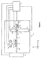
- FIG. 1 illustrates schematically a plan view of a possible embodiment of an image recording system 1 according to the invention.
- the image recording system 1 comprises two digital image recording means.
- the first image recording means is equipped with a (preferably low resolution) preview camera 2 having a field of view E
- the second image recording means comprises a high resolution and high magnification microscope objective 3, as well as a CCD camera 5 that captures the image mapped by the objective 3 and is connected to a control unit - in this case to a computer 4.
- the resolution of the CCD camera 5 is at least as high as that of the objective 3.
- an area with the size equal to the size of the field of view E and an area with the size equal to the size of the field of view M are digitized by the first and the second image recording means, respectively.
- a slide 6 (preferentially a microscope slide with a biological/tissue sample arranged thereon) fixed in a slide holding frame 7 is moved by means of a slide displacing mechanism.
- a slide displacing mechanism is disclosed e.g. by International Patent Appl. No. PCT/1B20051050351 , and hence it is not discussed here in more detail.
- the slide holding frame 7 is attached to a stage 17 through a known type of suspension, wherein the stage 17 is affixed to a threaded bar 9 driven by a stepping motor 8 capable of effecting displacement along the axis X.
- the threaded bar 9 brings about displacements of the stage 17 along a rail 10 lying in the axis X and, in turn, through the suspension, that of the slide holding frame 7 and the slide 6.
- the rail 10 is affixed to a rail 12 lying in the axis Z of a stepping motor 11 that is capable of bringing about displacements along the axis Z.
- the rail 10 can be moved by means of a threaded bar 13 driven by the stepping motor 11.
- both the slide holding frame 7 and the slide 6 can be moved in both the X and Z directions.
- the control of the stepping motors 8, 11 is equally performed by the control unit provided by the computer 4 in the present case.
- the plane spanned by the axes X, Z can also be a horizontal one; in this case it is adequate if the slide 6 is supported by the slide holding frame 7 from below.
- the axis Z is vertical and hence the slide 6 is arranged in an edgewise position (that is, when slides of a rectangular shape are used, as is the case in general in the field of medical diagnostics, preferably laid flatwise on its longer edge) within the slide holding frame 7.
- the plane spanned by the axes X, Z can be arranged actually at any angle relative to the horizontal.
- a slide dispensing means 14 is connected to an end of the rail 10 parallel to the X axis that loads (unloads) the slides 6 into (from) the slide holding frame 7 automatically.
- a slide dispensing means 14 is disclosed e.g. by International Publication Pamphlet No. WO2004/113989 .
- the illumination required for the image capturing is preferably provided on the one hand by a light source 15 arranged in the vicinity of the preview camera 2 and directed onto the slide 6, and on the other hand by a light source 16 arranged on a side of the slide 6 opposite the objective 3.
- a light source 15 arranged in the vicinity of the preview camera 2 and directed onto the slide 6, and on the other hand by a light source 16 arranged on a side of the slide 6 opposite the objective 3.
- both light sources 15, 16 are connected to the computer 4.
- transmitted light microscopy is discussed, however, in case of other kinds of microscopy the illumination of the slides 6 can be realized in different manners; optionally, the light source(s) 15 and/or 16 might be dispensable and, hence, can even be omitted.
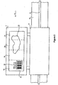
- Figure 2 shows the slide holding frame 7 connected to the stage 17, that is arranged on the rail 10 parallel to the axis X, via a known type of suspension and the slide 6 of rectangular shape fixed therein.
- a known type of a suspension can be realized by e.g. the parallel linkage taught by International Patent Appl. No. PCT/IB2005/050351 .
- the slide 6 is fastened by the frame 7 along its edges, that is, it has got no backplate, and therefore the slide 6 can be examined in transmitted light by the high magnification objective 3.
- the physical dimensions of the slide 6 are 1 inch by 3 inches (about 25,4 mm by 76,2 mm).
- the preview camera 2 applied can be e.g.
- the slide 6 can be imaged as a whole in four parts corresponding to regions 18, 19, 20, 21 denoted by dashed lines in the figure.
- the regions 18, 19, 20, 21 can also be defined in an overlapping manner, however, this is unnecessary as the displacement of the stage 17 can be controlled by the stepping motors 8, 11 connected to the computer 4 with a precision of microns, that is, with a much higher precision than the resolution of the preview camera 2.
- the regions 18, 19, 20, 21 can be captured in adjacent positions to one another and then can be simply matched together by applying a suitable software means.
- the first region 18 is the field of information of the slide 6; the data/pieces of information for identifying a sample 22 present on the slide 6, optionally any further notations carrying information, can be found here.
- the field of information may contain, for instance, a legend 23 comprising printed or hand-written letters and/or numbers, or a bar code 24, or a further piece of visual information applied onto the slide, or any combination thereof.
- the computer 4 can be equipped with an optical character recognition, in particular with a writing recognition routine.
- the text recognized can be stored as a text file together with the high magnification image files of the slide 6, or can be optionally used to define the filenames of the image files.
- bar codes 24 are used, the computer 4 can be equipped with a bar code recognition/reading routine and the (textual) information deciphered can be saved together with the high magnification image files of the slide 6.
- the advantage of this latter embodiment is that, on the one hand, by using the bar code 24, compared to handwriting, much more information can be included in the field of information, and on the other hand it is significantly cheaper to read the bar code 24 by means of a web camera and a bar code recognition/reading routine than to incorporate a complete bar code recognition/reading equipment into the system 1.
- the preview camera 2 is used merely to scan the regions 19, 20, 21 with a sample 22, while the region 18 with the field of information is read and processed by a bar code reader.
- the field of information is simply digitized by the preview camera 2, the image thus scanned is stored as an image file and shown to a user on demand who interprets the pieces of information that can be seen in the image himself/herself.
- the slides 6 to be digitized are arranged in the slide dispensing means 14 that loads the first slide 6 into the slide holding frame 7 by means of e.g. a robotic arm. If the image recording system 1 is not equipped with a slide dispensing means 14, the slide 6 is loaded into the image recording system 1 by the operator through an opening formed for this purpose, where the slide 6 goes into the slide holding frame 7. Upon control of the computer 4 the following operations are carried out.
- the stepping motor 8 moves the slide holding frame 7 along the rail 10 parallel to the axis X in front of the preview camera 2 so as to locate the first region 18 within the field of view E of the preview camera 2.
- a digital image of region 18 is captured, then the slide holding frame 7 is slided along the rail 10 by the stepping motor 8 so as to locate the second region 19 within the field of view E of the preview camera 2 and then a preview image of this region 19 is also captured. This procedure is then continued in a similar manner until a preview of the last region 21 is captured.
- the image of the first region 18 is processed according to the nature of the information found in the field of information by one of the procedures already mentioned, and is stored in the computer 4 or in a suitable data storage means connected to the computer 4 through a network or other ways. Processing of the region 18 can take place simultaneously with capturing the preview images of the other regions 19, 20, 21. Indeed, the image recording system 1, as well as the slide dispensing means 14 can also be formed in such a manner that the region 18 with the field of information be ahind, that is, when the slide 6 is moved towards the preview camera 2 along the rail 10, at first region 21, then region 20, then region 19 and finally region 18 reaches the preview camera 2.
- the recording can be commenced by region 21 and the preview images of regions 20, 19, 18 can be captured by displacing further the slide 6 along the axis X.
- a further possibility is to bring directly the region 18 in front of the preview camera 2 and then to capture regions 19, 20, 21 progressing backwards from it.
- the computer 4 might be equipped with an image recognition routine being capable of making a decision whether the region 18, 19, 20 or 21 at issue contains a field of information or a portion of the sample 22, and the digital image is processed accordingly.
- the digital preview images of the regions 19, 20, 21 are used for a software-based search of the location of the sample 22. This means that pixels belonging to the sample 22 are being searched within the regions 19, 20, 21 with a sample 22 of the digitized slide 6, and their spatial coordinates relative to the stage 17 within a reference frame defined by the stepping motors 8, 11 are determined. To the pixels classified as belonging to the sample 22, respective portions of the field of view M of the second image recording means (i.e. of the digital microscope) are assigned (preferably in an overlapping manner) and as a next step the thus defined fields of view M containing each a portion of the sample 22 are digitized at a high resolution.
- the second image recording means i.e. of the digital microscope
- X, Y coordinates are assigned and it is calculated into which positions the stage 17 should be moved in order that the field of view M concerned could be captured by the high magnification digital microscope.
- a 20x microscope objective 3 and a CCD camera 5 with the resolution of 1024 pixels by 768 pixels are used.
- an area with the size of about 0,23 ⁇ m by 0,23 ⁇ m of the slide 6 corresponds to a single pixel of the digital image captured by the second image recording means comprising the objective 3 and the CCD camera 5.
- at least an 5x microscope objective should be preferably used to end up with digital images that are of suitable quality for practical usage.
- the captured image Before the next field of view M containing a portion of the sample 22 could be digitized, the captured image must be downloaded to the computer 4. In one of the embodiments this takes generally about 65 ms, depending on the size of the image and the quality of the connection. This is longer than the time period required for the slide 6 to be moved into its next position. After exposition, the displacement of the stage 17 immediately commences, thus by the time the image has been downloaded, the slide 6 already occupies a new position to be scanned.
- the digital images and frames created via scanning are referred to by the adjective "digital", that is, from now on the concepts of digital field of view M, digital sample 22 and digital slide 6 are used.
- the digital fields of view M are matched along their adjacent edges (that can be optionally overlapping).
- a first possibility is to store the digital slide 6 containing the digital sample 22 composed of the digital fields of view M that are matched together.
- a further possibility is to store merely the data related to the matchings themselves (contiguity relations, overlappings of individual frames, measures of translation, etc.) along with the files of the individual digital fields of view M, and when the digital slide 6 is displayed the files of the digital fields of view M are displayed in harmony with the data related to the matchings.
- a half-way measure is also conceivable; a given number of neighbouring digital fields of view M is matched together in advance resulting in tiny digital fields, and the tiny fields as well as the data related to the matchings thereof are stored in files. In other cases only the files of the digital fields of view M are stored, and later on put together and looked at by means of a suitable digital slide displaying and manipulating routine.
- the slide holding frame 7 is returned to the slide dispensing means 14 by means of the stepping motors 8, 11, where the already scanned slide 6 is replaced via the robotic arm by a further slide 6 to be also scanned.
- the exchange of slides 6 can be effected manually or via other means.
- the computer 4 is connected to a local network or to the Internet. In this case storage, display and further operations do not take place definitely in the computer 4. Indeed, there is no need for the computer 4 performing control of the image recording system 1 and the image recording system 1 itself to be physically at the same location; the control itself can also be realized through a network.
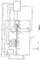
- Figure 3 illustrates the schematical plan view of a possible further embodiment of the image recording system according to the invention.
- the first image recording means comprises two elements: a preview camera 2 and a bar code scanner 25. These are preferentially arranged after each other along the rail 10.
- the bar code 24 is preferably placed within the field of information (i.e. within the first region 18) with an orientation that allows reading the bar code 24 by the bar code scanner 25 (i.e. with the orientation shown in Figure 2 ) when the slide 6 is passed along the axis X. In other cases, the slide 6 can also be translated along the axis Y when the bar code 24 appears in front of the bar code scanner 25.
- the preview camera 2 can be arranged so as to capture the region 26 with the sample 22 of the slide 6 as a single frame.
- the slide 6 can be divided into more than one sample containing regions 19, 20, 21 in this case, too.
Landscapes
- Physics & Mathematics (AREA)
- General Physics & Mathematics (AREA)
- Multimedia (AREA)
- Engineering & Computer Science (AREA)
- Chemical & Material Sciences (AREA)
- Analytical Chemistry (AREA)
- Biochemistry (AREA)
- Immunology (AREA)
- Pathology (AREA)
- Life Sciences & Earth Sciences (AREA)
- Computer Vision & Pattern Recognition (AREA)
- Health & Medical Sciences (AREA)
- Optics & Photonics (AREA)
- General Health & Medical Sciences (AREA)
- Microscoopes, Condenser (AREA)
- Television Signal Processing For Recording (AREA)
- Image Input (AREA)
- Image Processing (AREA)
- Optical Recording Or Reproduction (AREA)
- Apparatus For Radiation Diagnosis (AREA)
- Dot-Matrix Printers And Others (AREA)
- Projection Apparatus (AREA)
- Cameras Adapted For Combination With Other Photographic Or Optical Apparatuses (AREA)
Claims (17)
- Système automatisé d'enregistrement d'images numériques (1) adapté pour numériser des diapositives (6) ayant une ou plusieurs régions (26 ; 19, 20, 21) avec échantillon (22) et au moins une région séparée (18) avec un champ d'information, le système d'enregistrement d'images (1) comprenant un moyen de maintien de diapositives (7, 17), un mécanisme pour son actionnement, un premier moyen d'enregistrement d'images numériques, un deuxième moyen d'enregistrement d'images numériques à fort grossissement et une unité de commande (4) pour une commande par logiciel de la capture d'images automatisée, caractérisé en ce que le premier moyen d'enregistrement d'images numériques est prévu avec une caméra de prévisualisation (2) basse résolution pour capturer une image de prévisualisation numérique séparée de chacune des régions (26 ; 18, 19, 20, 21) sur la diapositive, de région à région, et l'unité de commande (4) est prévue avec (i) une routine pour extraire le contenu d'information de la (des) image(s) de prévisualisation de l'au moins une région (18) avec un champ d'information et (ii) une routine pour rechercher des pixels qui appartiennent à l'échantillon (22) dans les images de prévisualisation restantes.
- Système d'enregistrement d'images selon la revendication 1, caractérisé en ce que l'échantillon (22) est situé dans une région unique (26), dont une image de prévisualisation unique est prise par la caméra de prévisualisation (2).
- Système d'enregistrement d'images selon la revendication 1 ou 2, caractérisé en ce que le champ d'information comprend une légende (23) et/ou un code à barres (24), et/ou une autre information visuelle.
- Système d'enregistrement d'images selon la revendication 3, caractérisé en ce que ladite routine pour extraire le contenu d'information est une routine de reconnaissance de caractères optiques et/ou de balayage de code à barres pour lire le champ d'information.
- Système d'enregistrement d'images selon l'une quelconque des revendications 1 à 4, caractérisé en ce qu'un moyen de distribution de diapositives (14) est connecté au système (1) qui sur une commande de l'unité de commande (4) charge/décharge les diapositives (6) devant être numérisées automatiquement.
- Système d'enregistrement d'images selon l'une quelconque des revendications 1 à 5, caractérisé en ce que la caméra de prévisualisation basse résolution est une webcam avec une résolution de 640 pixels par 480 pixels.
- Système d'enregistrement d'images selon l'une quelconque des revendications 1 à 6, caractérisé en ce que le deuxième moyen d'enregistrement d'images numériques à fort grossissement comprend un objectif (3) de microscope unique et une unité de numérisation, préférablement une caméra CCD (5), pour numériser l'image représentée par l'objectif (3).
- Système d'enregistrement d'images selon l'une quelconque des revendications 1 à 7, caractérisé en ce que le mécanisme pour actionner le moyen de maintien de diapositives (7, 17) comprend des rails (10, 12) perpendiculaires l'un à l'autre, des barres filetées (9, 13) s'étendant le long des rails (10, 12) respectifs, des moteurs pas à pas (8, 11) entraînant des barres filetées (9, 13) respectives et un élément pour connecter les barres filetées (9, 13) avec le cadre de maintien de diapositives (7), préférablement sous la forme d'une suspension permettant des déplacements perpendiculaires par rapport au plan couvert par les rails (10, 12).
- Procédé de numérisation automatique de diapositives (6) ayant une ou plusieurs régions (26 ; 19, 20, 21) avec échantillon (22) et au moins une région séparée (18) avec un champ d'information par un système d'enregistrement d'images numériques (1) comprenant un moyen de maintien de diapositives (7, 17), un mécanisme pour l'actionnement de celui-ci, un premier moyen d'enregistrement d'images numériques, un deuxième moyen d'enregistrement d'images numériques à fort grossissement et une unité de commande (4) pour une commande par logiciel de la capture d'images automatisée, caractérisé par les étapes de(a) agencement d'une diapositive (6) à l'intérieur du moyen de maintien de diapositives (7, 17) ;(b) déplacement de la diapositive (6) par le mécanisme d'actionnement jusqu'au premier moyen d'enregistrement d'images numériques équipé d'une caméra de prévisualisation basse résolution ;(c) capture d'une image de prévisualisation numérique séparée de chacune de l'une ou plusieurs région(s) (26 ; 18, 19, 20, 21) sur la diapositive, de région à région, par la caméra de prévisualisation basse résolution (2) ;(d) par analyse des images de prévisualisation capturées, prise d'une décision quant à quelle région (26 ; 19, 20, 21) contient l'échantillon (22) et quelle région (18) contient un champ d'information ;(e) extraction de la (des) information(s) à partir de l'au moins une région (18) marquée comme contenant un champ d'information ;(f) détection de pixels appartenant à l'échantillon (22) dans la (les) image(s) de prévisualisation restantes ;(g) déplacement de la diapositive (6) jusqu'au deuxième moyen d'enregistrement d'images numériques par le mécanisme d'actionnement et capture d'une image numérique à fort grossissement de tous les champs de visée (M) qui correspondent aux pixels détectés ; et(h) stockage de ladite (desdites) information(s) extraite(s) et de ladite (desdites) image(s) numérique(s) à fort grossissement capturée(s) par le deuxième moyen d'enregistrement d'images numériques.
- Procédé selon la revendication 9, caractérisé en ce que les étapes (a) à (h) sont régies par l'unité de commande (4) qui est préférablement un ordinateur.
- Procédé selon la revendication 9 ou 10, caractérisé en ce que les images numériques à fort grossissement sont mises en correspondance le long de leurs bords adjacents, facultativement en chevauchement, et sont affichées.
- Procédé selon l'une quelconque des revendications 9 à 11, caractérisé en ce que le champ d'information comprend une légende (23) et/ou un code à barres (24), et/ou une autre information visuelle supplémentaire.
- Procédé selon la revendication 12, caractérisé en ce que la (les) image(s) de l'au moins une région (18) du champ d'information est (sont) traitée(s) et/ou affichée(s) au moyen d'une routine de reconnaissance de caractères optiques et/ou d'une routine de balayage de code à barres.
- Procédé selon l'une quelconque des revendications 9 à 13, caractérisé en ce que la caméra de prévisualisation basse résolution est une webcam avec une résolution de 640 pixels par 480 pixels.
- Procédé selon l'une quelconque des revendications 9 à 14, caractérisé en ce que à l'étape (a), la diapositive (6) est agencée dans le cadre de maintien de diapositives (7) par un moyen de distribution de diapositives (14) qui charge/décharge la diapositive (6) automatiquement.
- Procédé selon la revendication 8, caractérisé en ce que l'extraction du contenu d'information du champ d'information est effectuée par un affichage de l'image de prévisualisation du champ de visée pour un utilisateur.
- Procédé selon l'une quelconque des revendications 9 à 16, caractérisé en ce qu'étant exécuté sur une pluralité de diapositives (6) l'une après l'autre, dans lequel les diapositives (6) sont distribuées du moyen de distribution de diapositives (14) dans le moyen de maintien de diapositives (7, 17) l'une après l'autre sur un signal de l'unité de commande (4).
Applications Claiming Priority (2)
| Application Number | Priority Date | Filing Date | Title |
|---|---|---|---|
| HU0600177A HUP0600177A2 (en) | 2006-03-03 | 2006-03-03 | Equipment for and method of digitizing slides by automated digital image recording system |
| PCT/HU2007/000018 WO2007099382A1 (fr) | 2006-03-03 | 2007-03-05 | Système automatisé d'enregistrement d'images numériques pour numérisation de diapositives et méthode de numérisation de diapositives |
Publications (3)
| Publication Number | Publication Date |
|---|---|
| EP1994398A1 EP1994398A1 (fr) | 2008-11-26 |
| EP1994398B1 true EP1994398B1 (fr) | 2009-08-12 |
| EP1994398B8 EP1994398B8 (fr) | 2010-02-03 |
Family
ID=89986622
Family Applications (1)
| Application Number | Title | Priority Date | Filing Date |
|---|---|---|---|
| EP07713006A Active EP1994398B8 (fr) | 2006-03-03 | 2007-03-05 | Système automatisé d'enregistrement d'images numériques pour numérisation de diapositives et méthode de numérisation de diapositives |
Country Status (11)
| Country | Link |
|---|---|
| US (1) | US20090046192A1 (fr) |
| EP (1) | EP1994398B8 (fr) |
| JP (1) | JP2009528580A (fr) |
| CN (1) | CN101395465A (fr) |
| AT (1) | ATE439581T1 (fr) |
| BR (1) | BRPI0708550A2 (fr) |
| DE (1) | DE602007001956D1 (fr) |
| DK (1) | DK1994398T3 (fr) |
| HU (1) | HUP0600177A2 (fr) |
| NO (1) | NO20084054L (fr) |
| WO (1) | WO2007099382A1 (fr) |
Families Citing this family (21)
| Publication number | Priority date | Publication date | Assignee | Title |
|---|---|---|---|---|
| WO2011038402A2 (fr) * | 2009-09-28 | 2011-03-31 | Bryan Dangott | Dispositif, système et procédé pour simuler le mouvement physique d'une image numérique |
| CN102547205A (zh) * | 2011-12-21 | 2012-07-04 | 广东威创视讯科技股份有限公司 | 超高分辨率图像的显示方法与系统 |
| CN102707425B (zh) * | 2012-06-21 | 2014-04-16 | 爱威科技股份有限公司 | 图像处理方法和装置 |
| KR101538687B1 (ko) * | 2013-08-28 | 2015-07-23 | 주식회사 아세테크 | 검체 슬라이드 보관 처리 시스템 |
| EP3268715B1 (fr) | 2015-03-11 | 2024-09-25 | TissueVision, Inc. | Système et méthodes de coloration et d'imagerie en série |
| JP6841609B2 (ja) | 2015-07-10 | 2021-03-10 | 3スキャン インコーポレイテッド | 組織学的染色の空間的多重化 |
| JP2017102381A (ja) * | 2015-12-04 | 2017-06-08 | オリンパス株式会社 | 顕微鏡システム |
| KR20170088064A (ko) | 2016-01-22 | 2017-08-01 | 에스프린팅솔루션 주식회사 | 화상 취득 장치 및 화상 형성 장치 |
| US20180045937A1 (en) * | 2016-08-10 | 2018-02-15 | Zeta Instruments, Inc. | Automated 3-d measurement |
| CN106331411A (zh) * | 2016-08-23 | 2017-01-11 | 宁波江丰生物信息技术有限公司 | 一种数字切片制作装置 |
| WO2018094290A1 (fr) * | 2016-11-18 | 2018-05-24 | Tissuevision, Inc. | Système et procédés automatisés de capture, d'indexation et de stockage de sections de tissus |
| CN110140129B (zh) * | 2016-12-30 | 2023-10-17 | 徕卡生物系统成像股份有限公司 | 使用双光学路径和单成像传感器的低分辨率载片成像和载片标签成像以及高分辨率载片成像 |
| JP6972157B2 (ja) * | 2017-10-16 | 2021-11-24 | 株式会社日立ハイテク | 撮像装置 |
| PT3477286T (pt) * | 2017-10-25 | 2023-04-24 | Hoffmann La Roche | Métodos e dispositivos para realizar uma medição analítica |
| CN110132967B (zh) * | 2019-05-14 | 2021-10-08 | 南京凯泽瑞兹光电科技有限公司 | 一种数字病理切片扫描器 |
| CN110298905A (zh) * | 2019-07-02 | 2019-10-01 | 麦克奥迪(厦门)医疗诊断系统有限公司 | 一种基于生物标本切片生成数字切片的方法和装置 |
| CN110618509B (zh) * | 2019-09-09 | 2021-07-02 | 杭州憶盛医疗科技有限公司 | 一种基于切片数字化自动扫描仪的光学部件切换装置 |
| CN111443475B (zh) * | 2020-05-20 | 2022-10-28 | 广州市汇研微电子技术有限公司 | 一种物镜自动定位扫描玻片的方法及装置 |
| EP4241062A4 (fr) | 2020-11-11 | 2024-01-17 | George Mason Research Foundation, Inc. | Chimie de visualisation de microdissection par capture laser |
| CN112508952B (zh) * | 2021-02-05 | 2021-05-04 | 宁波兰茜生物科技有限公司 | 一种病理切片双物镜自适应扫描控制方法及系统 |
| CN113568155A (zh) * | 2021-06-21 | 2021-10-29 | 深圳视见医疗科技有限公司 | 一种载玻片 |
Family Cites Families (14)
| Publication number | Priority date | Publication date | Assignee | Title |
|---|---|---|---|---|
| JPS61266939A (ja) * | 1985-05-22 | 1986-11-26 | Japan Organo Co Ltd | 走査型電子顕微鏡を用いた微粒子測定装置 |
| US5740270A (en) * | 1988-04-08 | 1998-04-14 | Neuromedical Systems, Inc. | Automated cytological specimen classification system and method |
| CA2077781A1 (fr) * | 1991-09-23 | 1993-03-24 | James W. Bacus | Methode et appareil de dosage automatise de prelevements bilologiques |
| DK0745243T3 (da) * | 1994-02-14 | 2004-04-19 | Autocyte North Carolina Llc | Fremgangsmåder til automatiseret klassificering af cytologiske prøver |
| US6151405A (en) * | 1996-11-27 | 2000-11-21 | Chromavision Medical Systems, Inc. | System and method for cellular specimen grading |
| DE69627183T2 (de) * | 1995-11-30 | 2004-01-29 | Chromavision Med Sys Inc | Verfahren zur automatischen bildanalyse biologischer proben |
| US6031930A (en) * | 1996-08-23 | 2000-02-29 | Bacus Research Laboratories, Inc. | Method and apparatus for testing a progression of neoplasia including cancer chemoprevention testing |
| US6711283B1 (en) * | 2000-05-03 | 2004-03-23 | Aperio Technologies, Inc. | Fully automatic rapid microscope slide scanner |
| US7155049B2 (en) * | 2001-01-11 | 2006-12-26 | Trestle Acquisition Corp. | System for creating microscopic digital montage images |
| US6993169B2 (en) * | 2001-01-11 | 2006-01-31 | Trestle Corporation | System and method for finding regions of interest for microscopic digital montage imaging |
| JP4766360B2 (ja) * | 2001-02-26 | 2011-09-07 | 株式会社安川電機 | 平面型x−yテーブル |
| JP4806875B2 (ja) * | 2001-09-12 | 2011-11-02 | 株式会社ニコン | 顕微鏡装置 |
| WO2005036451A1 (fr) * | 2003-10-08 | 2005-04-21 | Lifespan Biosciences, Inc. | Mappage automatise d'echantillons tissulaires sur lame de microscope et acquisition d'images |
| US7627153B2 (en) * | 2005-08-04 | 2009-12-01 | Carl Zeiss Microimaging Gmbh | Repositioning inaccuracies in an automated imaging system |
-
2006
- 2006-03-03 HU HU0600177A patent/HUP0600177A2/hu unknown
-
2007
- 2007-03-05 AT AT07713006T patent/ATE439581T1/de not_active IP Right Cessation
- 2007-03-05 US US12/281,566 patent/US20090046192A1/en not_active Abandoned
- 2007-03-05 BR BRPI0708550-8A patent/BRPI0708550A2/pt not_active IP Right Cessation
- 2007-03-05 CN CNA2007800076422A patent/CN101395465A/zh active Pending
- 2007-03-05 EP EP07713006A patent/EP1994398B8/fr active Active
- 2007-03-05 JP JP2008557835A patent/JP2009528580A/ja active Pending
- 2007-03-05 WO PCT/HU2007/000018 patent/WO2007099382A1/fr not_active Ceased
- 2007-03-05 DE DE602007001956T patent/DE602007001956D1/de active Active
- 2007-03-05 DK DK07713006T patent/DK1994398T3/da active
-
2008
- 2008-09-24 NO NO20084054A patent/NO20084054L/no not_active Application Discontinuation
Also Published As
| Publication number | Publication date |
|---|---|
| BRPI0708550A2 (pt) | 2011-05-31 |
| HU0600177D0 (en) | 2006-05-29 |
| WO2007099382A1 (fr) | 2007-09-07 |
| ATE439581T1 (de) | 2009-08-15 |
| CN101395465A (zh) | 2009-03-25 |
| HK1123094A1 (en) | 2009-06-05 |
| EP1994398A1 (fr) | 2008-11-26 |
| US20090046192A1 (en) | 2009-02-19 |
| JP2009528580A (ja) | 2009-08-06 |
| NO20084054L (no) | 2008-11-21 |
| HUP0600177A2 (en) | 2009-03-02 |
| DK1994398T3 (da) | 2009-12-14 |
| EP1994398B8 (fr) | 2010-02-03 |
| DE602007001956D1 (de) | 2009-09-24 |
Similar Documents
| Publication | Publication Date | Title |
|---|---|---|
| EP1994398B1 (fr) | Système automatisé d'enregistrement d'images numériques pour numérisation de diapositives et méthode de numérisation de diapositives | |
| US7250963B2 (en) | Microscopic image capture apparatus | |
| JP6462763B2 (ja) | デジタル顕微鏡を備えたシステム及びこれを用いた試料の検査方法 | |
| AU2007219377B2 (en) | Cytological imaging systems and methods | |
| CN100424166C (zh) | 组织样品自动染色方法和装置 | |
| EP3538863B1 (fr) | Instrument automatisé de dissection de tissu et procédés d'utilisation correspondants | |
| JP7566733B2 (ja) | デジタル撮像システムおよび方法 | |
| US20090196526A1 (en) | Microscopy system having automatic and interactive modes for forming a magnified mosaic image and associated method | |
| US20060002636A1 (en) | Data structure of an image storage and retrieval system | |
| EP2024772B1 (fr) | Procédé et système de numérisation d'un spécimen à points cibles fluorescents | |
| CN111275016A (zh) | 一种玻片扫描影像采集与分析方法及装置 | |
| JP5132050B2 (ja) | 標本撮像装置及び標本撮像方法とその装置を制御するプログラム、並びに、標本分析装置 | |
| US7653260B2 (en) | System and method of registering field of view | |
| WO2015121313A1 (fr) | Obtention d'informations concernant un échantillon au moyen d'un système de microdissection laser | |
| CN108647549B (zh) | 条码图像的处理方法、装置及系统 | |
| HK1123094B (en) | Automated digital image recording system for and method of digitizing slides | |
| CN114442296B (zh) | 一种用于显微镜的采图方法及医学检测装置、存储介质 | |
| US20260122350A1 (en) | Slide scan device and operating method therefor | |
| KR102739395B1 (ko) | 자동 초점 수행 장치 및 방법 | |
| KR102721930B1 (ko) | 슬라이드 트레이에 대한 프리뷰 이미지를 이용하여 슬라이드를 스캔하는 장치 및 그 방법 |
Legal Events
| Date | Code | Title | Description |
|---|---|---|---|
| PUAI | Public reference made under article 153(3) epc to a published international application that has entered the european phase |
Free format text: ORIGINAL CODE: 0009012 |
|
| 17P | Request for examination filed |
Effective date: 20080929 |
|
| AK | Designated contracting states |
Kind code of ref document: A1 Designated state(s): AT BE BG CH CY CZ DE DK EE ES FI FR GB GR HU IE IS IT LI LT LU LV MC MT NL PL PT RO SE SI SK TR |
|
| GRAP | Despatch of communication of intention to grant a patent |
Free format text: ORIGINAL CODE: EPIDOSNIGR1 |
|
| REG | Reference to a national code |
Ref country code: HK Ref legal event code: DE Ref document number: 1123094 Country of ref document: HK |
|
| GRAS | Grant fee paid |
Free format text: ORIGINAL CODE: EPIDOSNIGR3 |
|
| GRAA | (expected) grant |
Free format text: ORIGINAL CODE: 0009210 |
|
| AK | Designated contracting states |
Kind code of ref document: B1 Designated state(s): AT BE BG CH CY CZ DE DK EE ES FI FR GB GR HU IE IS IT LI LT LU LV MC MT NL PL PT RO SE SI SK TR |
|
| REG | Reference to a national code |
Ref country code: GB Ref legal event code: FG4D |
|
| REG | Reference to a national code |
Ref country code: CH Ref legal event code: EP |
|
| REG | Reference to a national code |
Ref country code: IE Ref legal event code: FG4D |
|
| REF | Corresponds to: |
Ref document number: 602007001956 Country of ref document: DE Date of ref document: 20090924 Kind code of ref document: P |
|
| REG | Reference to a national code |
Ref country code: SE Ref legal event code: TRGR |
|
| REG | Reference to a national code |
Ref country code: DK Ref legal event code: T3 |
|
| RAP2 | Party data changed (patent owner data changed or rights of a patent transferred) |
Owner name: 3DHISTECH KFT |
|
| LTIE | Lt: invalidation of european patent or patent extension |
Effective date: 20090812 |
|
| PG25 | Lapsed in a contracting state [announced via postgrant information from national office to epo] |
Ref country code: AT Free format text: LAPSE BECAUSE OF FAILURE TO SUBMIT A TRANSLATION OF THE DESCRIPTION OR TO PAY THE FEE WITHIN THE PRESCRIBED TIME-LIMIT Effective date: 20090812 Ref country code: ES Free format text: LAPSE BECAUSE OF FAILURE TO SUBMIT A TRANSLATION OF THE DESCRIPTION OR TO PAY THE FEE WITHIN THE PRESCRIBED TIME-LIMIT Effective date: 20091123 Ref country code: IS Free format text: LAPSE BECAUSE OF FAILURE TO SUBMIT A TRANSLATION OF THE DESCRIPTION OR TO PAY THE FEE WITHIN THE PRESCRIBED TIME-LIMIT Effective date: 20091212 Ref country code: LT Free format text: LAPSE BECAUSE OF FAILURE TO SUBMIT A TRANSLATION OF THE DESCRIPTION OR TO PAY THE FEE WITHIN THE PRESCRIBED TIME-LIMIT Effective date: 20090812 |
|
| NLT2 | Nl: modifications (of names), taken from the european patent patent bulletin |
Owner name: 3DHISTECH KFT Effective date: 20091216 |
|
| PG25 | Lapsed in a contracting state [announced via postgrant information from national office to epo] |
Ref country code: SI Free format text: LAPSE BECAUSE OF FAILURE TO SUBMIT A TRANSLATION OF THE DESCRIPTION OR TO PAY THE FEE WITHIN THE PRESCRIBED TIME-LIMIT Effective date: 20090812 Ref country code: PL Free format text: LAPSE BECAUSE OF FAILURE TO SUBMIT A TRANSLATION OF THE DESCRIPTION OR TO PAY THE FEE WITHIN THE PRESCRIBED TIME-LIMIT Effective date: 20090812 Ref country code: LV Free format text: LAPSE BECAUSE OF FAILURE TO SUBMIT A TRANSLATION OF THE DESCRIPTION OR TO PAY THE FEE WITHIN THE PRESCRIBED TIME-LIMIT Effective date: 20090812 |
|
| PG25 | Lapsed in a contracting state [announced via postgrant information from national office to epo] |
Ref country code: BG Free format text: LAPSE BECAUSE OF FAILURE TO SUBMIT A TRANSLATION OF THE DESCRIPTION OR TO PAY THE FEE WITHIN THE PRESCRIBED TIME-LIMIT Effective date: 20091112 Ref country code: PT Free format text: LAPSE BECAUSE OF FAILURE TO SUBMIT A TRANSLATION OF THE DESCRIPTION OR TO PAY THE FEE WITHIN THE PRESCRIBED TIME-LIMIT Effective date: 20091212 |
|
| REG | Reference to a national code |
Ref country code: HK Ref legal event code: GR Ref document number: 1123094 Country of ref document: HK |
|
| PG25 | Lapsed in a contracting state [announced via postgrant information from national office to epo] |
Ref country code: EE Free format text: LAPSE BECAUSE OF FAILURE TO SUBMIT A TRANSLATION OF THE DESCRIPTION OR TO PAY THE FEE WITHIN THE PRESCRIBED TIME-LIMIT Effective date: 20090812 Ref country code: RO Free format text: LAPSE BECAUSE OF FAILURE TO SUBMIT A TRANSLATION OF THE DESCRIPTION OR TO PAY THE FEE WITHIN THE PRESCRIBED TIME-LIMIT Effective date: 20090812 Ref country code: CZ Free format text: LAPSE BECAUSE OF FAILURE TO SUBMIT A TRANSLATION OF THE DESCRIPTION OR TO PAY THE FEE WITHIN THE PRESCRIBED TIME-LIMIT Effective date: 20090812 |
|
| PG25 | Lapsed in a contracting state [announced via postgrant information from national office to epo] |
Ref country code: SK Free format text: LAPSE BECAUSE OF FAILURE TO SUBMIT A TRANSLATION OF THE DESCRIPTION OR TO PAY THE FEE WITHIN THE PRESCRIBED TIME-LIMIT Effective date: 20090812 |
|
| PLBE | No opposition filed within time limit |
Free format text: ORIGINAL CODE: 0009261 |
|
| STAA | Information on the status of an ep patent application or granted ep patent |
Free format text: STATUS: NO OPPOSITION FILED WITHIN TIME LIMIT |
|
| 26N | No opposition filed |
Effective date: 20100517 |
|
| BERE | Be: lapsed |
Owner name: 3DHISTECH KFT Effective date: 20100331 |
|
| REG | Reference to a national code |
Ref country code: NL Ref legal event code: V1 Effective date: 20101001 |
|
| PG25 | Lapsed in a contracting state [announced via postgrant information from national office to epo] |
Ref country code: MC Free format text: LAPSE BECAUSE OF NON-PAYMENT OF DUE FEES Effective date: 20100331 Ref country code: GR Free format text: LAPSE BECAUSE OF FAILURE TO SUBMIT A TRANSLATION OF THE DESCRIPTION OR TO PAY THE FEE WITHIN THE PRESCRIBED TIME-LIMIT Effective date: 20091113 |
|
| EUG | Se: european patent has lapsed | ||
| REG | Reference to a national code |
Ref country code: DK Ref legal event code: EBP |
|
| PG25 | Lapsed in a contracting state [announced via postgrant information from national office to epo] |
Ref country code: FI Free format text: LAPSE BECAUSE OF NON-PAYMENT OF DUE FEES Effective date: 20100305 |
|
| REG | Reference to a national code |
Ref country code: FR Ref legal event code: ST Effective date: 20101130 |
|
| PG25 | Lapsed in a contracting state [announced via postgrant information from national office to epo] |
Ref country code: FR Free format text: LAPSE BECAUSE OF NON-PAYMENT OF DUE FEES Effective date: 20100331 Ref country code: NL Free format text: LAPSE BECAUSE OF NON-PAYMENT OF DUE FEES Effective date: 20101001 Ref country code: IE Free format text: LAPSE BECAUSE OF NON-PAYMENT OF DUE FEES Effective date: 20100305 |
|
| PG25 | Lapsed in a contracting state [announced via postgrant information from national office to epo] |
Ref country code: BE Free format text: LAPSE BECAUSE OF NON-PAYMENT OF DUE FEES Effective date: 20100331 |
|
| PG25 | Lapsed in a contracting state [announced via postgrant information from national office to epo] |
Ref country code: IT Free format text: LAPSE BECAUSE OF FAILURE TO SUBMIT A TRANSLATION OF THE DESCRIPTION OR TO PAY THE FEE WITHIN THE PRESCRIBED TIME-LIMIT Effective date: 20090812 |
|
| PG25 | Lapsed in a contracting state [announced via postgrant information from national office to epo] |
Ref country code: MT Free format text: LAPSE BECAUSE OF FAILURE TO SUBMIT A TRANSLATION OF THE DESCRIPTION OR TO PAY THE FEE WITHIN THE PRESCRIBED TIME-LIMIT Effective date: 20090812 Ref country code: DK Free format text: LAPSE BECAUSE OF NON-PAYMENT OF DUE FEES Effective date: 20100331 |
|
| REG | Reference to a national code |
Ref country code: CH Ref legal event code: PL |
|
| PG25 | Lapsed in a contracting state [announced via postgrant information from national office to epo] |
Ref country code: CH Free format text: LAPSE BECAUSE OF NON-PAYMENT OF DUE FEES Effective date: 20110331 Ref country code: LI Free format text: LAPSE BECAUSE OF NON-PAYMENT OF DUE FEES Effective date: 20110331 |
|
| PG25 | Lapsed in a contracting state [announced via postgrant information from national office to epo] |
Ref country code: CY Free format text: LAPSE BECAUSE OF FAILURE TO SUBMIT A TRANSLATION OF THE DESCRIPTION OR TO PAY THE FEE WITHIN THE PRESCRIBED TIME-LIMIT Effective date: 20090812 |
|
| PG25 | Lapsed in a contracting state [announced via postgrant information from national office to epo] |
Ref country code: SE Free format text: LAPSE BECAUSE OF NON-PAYMENT OF DUE FEES Effective date: 20100306 Ref country code: HU Free format text: LAPSE BECAUSE OF FAILURE TO SUBMIT A TRANSLATION OF THE DESCRIPTION OR TO PAY THE FEE WITHIN THE PRESCRIBED TIME-LIMIT Effective date: 20100213 Ref country code: LU Free format text: LAPSE BECAUSE OF NON-PAYMENT OF DUE FEES Effective date: 20100305 |
|
| PG25 | Lapsed in a contracting state [announced via postgrant information from national office to epo] |
Ref country code: TR Free format text: LAPSE BECAUSE OF FAILURE TO SUBMIT A TRANSLATION OF THE DESCRIPTION OR TO PAY THE FEE WITHIN THE PRESCRIBED TIME-LIMIT Effective date: 20090812 |
|
| PGFP | Annual fee paid to national office [announced via postgrant information from national office to epo] |
Ref country code: GB Payment date: 20260324 Year of fee payment: 20 |
|
| PGFP | Annual fee paid to national office [announced via postgrant information from national office to epo] |
Ref country code: DE Payment date: 20260319 Year of fee payment: 20 |