EP1994608B1 - Steckerverriegelungsanordnung - Google Patents
Steckerverriegelungsanordnung Download PDFInfo
- Publication number
- EP1994608B1 EP1994608B1 EP07757644A EP07757644A EP1994608B1 EP 1994608 B1 EP1994608 B1 EP 1994608B1 EP 07757644 A EP07757644 A EP 07757644A EP 07757644 A EP07757644 A EP 07757644A EP 1994608 B1 EP1994608 B1 EP 1994608B1
- Authority
- EP
- European Patent Office
- Prior art keywords
- plug
- housing
- locking assembly
- spring
- open space
- Prior art date
- Legal status (The legal status is an assumption and is not a legal conclusion. Google has not performed a legal analysis and makes no representation as to the accuracy of the status listed.)
- Not-in-force
Links
- 230000000881 depressing effect Effects 0.000 claims description 3
- 238000003780 insertion Methods 0.000 description 16
- 230000037431 insertion Effects 0.000 description 16
- 230000013011 mating Effects 0.000 description 5
- 238000009434 installation Methods 0.000 description 2
- IYHIWXOXDZSAEO-SVBPBHIXSA-N 3-[1-[(2s)-1-[4-[4-[4-[(2s)-2-[4-(2-carboxyethyl)triazol-1-yl]propanoyl]piperazin-1-yl]-6-[2-[2-(2-prop-2-ynoxyethoxy)ethoxy]ethylamino]-1,3,5-triazin-2-yl]piperazin-1-yl]-1-oxopropan-2-yl]triazol-4-yl]propanoic acid Chemical compound N1([C@@H](C)C(=O)N2CCN(CC2)C=2N=C(NCCOCCOCCOCC#C)N=C(N=2)N2CCN(CC2)C(=O)[C@H](C)N2N=NC(CCC(O)=O)=C2)C=C(CCC(O)=O)N=N1 IYHIWXOXDZSAEO-SVBPBHIXSA-N 0.000 description 1
- 238000004891 communication Methods 0.000 description 1
- 238000010276 construction Methods 0.000 description 1
- 210000004905 finger nail Anatomy 0.000 description 1
- 230000007246 mechanism Effects 0.000 description 1
- 238000000034 method Methods 0.000 description 1
- 238000012986 modification Methods 0.000 description 1
- 230000004048 modification Effects 0.000 description 1
- 238000000465 moulding Methods 0.000 description 1
- 230000008569 process Effects 0.000 description 1
- 238000012545 processing Methods 0.000 description 1
Images







Classifications
-
- H—ELECTRICITY
- H01—ELECTRIC ELEMENTS
- H01R—ELECTRICALLY-CONDUCTIVE CONNECTIONS; STRUCTURAL ASSOCIATIONS OF A PLURALITY OF MUTUALLY-INSULATED ELECTRICAL CONNECTING ELEMENTS; COUPLING DEVICES; CURRENT COLLECTORS
- H01R13/00—Details of coupling devices of the kinds covered by groups H01R12/70 or H01R24/00 - H01R33/00
- H01R13/62—Means for facilitating engagement or disengagement of coupling parts or for holding them in engagement
- H01R13/639—Additional means for holding or locking coupling parts together, after engagement, e.g. separate keylock, retainer strap
- H01R13/6397—Additional means for holding or locking coupling parts together, after engagement, e.g. separate keylock, retainer strap with means for preventing unauthorised use
-
- H—ELECTRICITY
- H01—ELECTRIC ELEMENTS
- H01R—ELECTRICALLY-CONDUCTIVE CONNECTIONS; STRUCTURAL ASSOCIATIONS OF A PLURALITY OF MUTUALLY-INSULATED ELECTRICAL CONNECTING ELEMENTS; COUPLING DEVICES; CURRENT COLLECTORS
- H01R24/00—Two-part coupling devices, or either of their cooperating parts, characterised by their overall structure
- H01R24/60—Contacts spaced along planar side wall transverse to longitudinal axis of engagement
- H01R24/62—Sliding engagements with one side only, e.g. modular jack coupling devices
- H01R24/64—Sliding engagements with one side only, e.g. modular jack coupling devices for high frequency, e.g. RJ 45
Definitions
- the present invention relates to a plug locking assembly and, more particularly, to a plug locking assembly for preventing unwanted access to a plug positioned within an associated jack.
- Modem telecommunication and data processing equipment often includes modular plugs that engage jacks or receptacles to create electrical connections.
- Typical modular plugs include an integral resilient spring or latch mechanism for releasably securing the plug within the jack.
- the springs or latches comprise a tab that projects out of the receptacle after insertion. Because these tabs are readily accessible by fingernails and/or small tools, the unauthorized removal of modular plugs from their corresponding jacks is a common problem.
- the slidable housing receives the mating portion at the first end and the slidable housing is adapted to slide along the mating portion and engage the mating portion.
- a cable is connected to the mating portion and extends through the second end of the slidable housing.
- a locking member is in operable communication with both the slidable housing and the cable.
- WO-A1-075859 discloses a safety device for a plug-in connector comprising a collar shaped housing which can be fixed in front of the socket connector by securing means, whereby the housing is configured in such a way that when the plug is inserted into the socket, the end of the unlocking clip protruding from the socket connector comes to rest fully inside the housing.
- the housing comprises a keyhole which is adapted and arranged in relation to the position of the unlocking clip in such a way that it can be unlocked by a key engaging in the keyhole of the unlocking clip, whereupon the plug-in connector can be removed.
- the present invention relates to an improved plug locking assembly.
- the plug locking assembly comprises a housing comprising a top portion, a bottom portion and opposing sidewalls defining an open space therebetween, the open space for receiving and carrying a plug comprising a spring.
- the open space is dimensioned such that at least a portion of the spring extends beyond the open space with the plug engaged within the housing.
- the plug locking assembly of this embodiment further comprises a plug protection member connected to the housing.
- the plug protection member comprises a surface spaced apart from the open space and positioned to overlie at least a portion of the spring with the plug engaged within the housing.
- the plug locking assembly comprises a housing, a locking clip and an angled surface formed on at least one of the locking clip and the housing.
- the housing comprises a top portion, a bottom portion and opposing sidewalls defining an open space therebetween.
- the open space is designed to receive and carry a plug comprising a cantilevered spring with a fixed end and a free end.
- the locking clip is releasably securable to the housing.
- the angled surface is positioned to overlie and retain the free end of the cantilevered spring with the plug engaged within the housing.
- the plug locking assembly comprises a housing and a locking clip.
- the housing comprises a top portion, a bottom portion and opposing sidewalls defining an open space therebetween.
- the open space receives and carries a plug comprising a cantilevered spring with a free end and a fixed end.
- An internal surface of the bottom portion comprises a ramp and the housing comprises a stop surface defining a channel therebetween.
- the locking clip is releasably securable to the housing, and is designed to secure the plug into position within the housing.
- the foregoing embodiments may include various additional features.
- the housing may, for example, include an internal surface comprising a ramp and a stop surface defining a channel therebetween.
- the internal surface and the stop surface may be positioned in different planes.
- the housing may also include two or more windows for receiving a plug removal tool and the internal width of at least a portion of the open space within the housing may be tapered.
- Internal surfaces of housing sidewalls may comprise two or more slots. Additionally or alternatively, these internal surfaces may comprise guide rails extending longitudinally throughout the housing and oriented in a parallel relationship to one another.
- a spring depression member associated with the housing may be positioned to interact with the spring of the plug.
- the housing may further comprise a tab extending outwardly therefrom.
- the tab may comprise a top surface and opposing sidewalls, with the underside of the top surface comprising a downwardly facing hook.
- An external surface of the bottom portion of the housing may comprise a core out.
- the plug protection member may exhibit various configurations and be formed integrally on the housing or the locking clip.
- the plug protection member may comprise opposing arms connected to a top planar surface, the arms capable of movement to reposition the top planar surface.
- the locking clip may further comprise a spring retaining member comprising an angled surface positioned to overlie and retain the spring.
- the locking clip releasably may also include opposing flanges adapted to mate with the two or more slots positioned on the internal surfaces of the housing.
- the locking clip may comprise a T-shaped member adapted to ride over the upper guide rails of the housing.
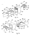
- Fig. 1A is a rear exploded perspective view of a plug and the plug locking assembly of the present invention
- Fig. 1B is a rear assembled perspective view of Fig. 1A ;
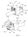
- Fig. 2A is a front exploded perspective view of a plug and the plug locking assembly of the present invention:
- Fig. 2B is a front assembled perspective view of Fig. 2A ;
- Fig. 2C is a bottom perspective view of Fig. 2B ;
- Fig. 3 is an end elevational view of Fig. 2C ;
- Fig. 4 is an enlarged view of detail AB of Fig. 3 ;
- Fig. 5 is a cross-sectional view along line AC-AC of Fig. 3 ;
- Fig. 6 is an enlarged view of detail AD of Fig. 5 ;
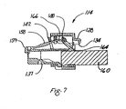
- Fig. 7 is a cross-sectional view along line AA-AA of Fig. 3 ;
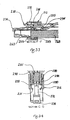
- Fig. 8 is a top perspective view of the plug locking assembly engaging a plug positioned within a jack
- Fig. 9 is a side elevational view of Fig. 8 ;
- Fig. 10 is an end elevational view of Fig. 8 ;
- Fig. 11A is a cross-sectional view along line AE-AE of Fig. 10 ;
- Fig. 11B is a cross-sectional view along line AF-AF of Fig. 10 ;
- Fig. 12 is a top perspective view of Fig 8 , with a removal tool positioned to engage the housing of the plug locking assembly;
- Fig. 13 is a bottom perspective view of Fig. 12 , with the removal tool positioned to engage the housing of the plug locking assembly;
- Fig. 14 is a bottom perspective view similar to Fig. 13 , with the removal tool engaged with the housing of the plug locking assembly;
- Fig. 15 is a bottom perspective view similar to Fig. 13 , after the removal tool removes the plug and the plug locking assembly from the jack;
- Fig. 16 is an end elevational view of Fig. 13 ;
- Fig. 17A is a cross-sectional view along line AG-AG of Fig. 16 ;
- Fig. 17B is a cross-sectional view along line AH-AH of Fig. 16 ;
- Fig. 18 is a rear exploded perspective view of a plug locking assembly according to another embodiment of the present invention.
- Fig. 19 is a front exploded perspective view of the plug locking assembly of Fig. 18 ;
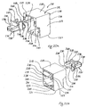
- Fig. 20A is a front exploded perspective view of yet another embodiment of the plug locking assembly of the present invention.
- Fig. 20B is a rear perspective view of Fig. 20A :
- Fig. 21 is an end elevational view of Figs. 20A and 20B , with the locking clip installed in the housing;
- Fig. 22 is a cross-sectional view along line AA of Fig. 21 ;
- Fig. 23 is a cross-sectional view along line BB of Fig. 21 ;
- Fig. 24A is a front exploded perspective view of the plug locking assembly of Fig. 20A and a plug;
- Fig. 24B is a rear perspective view of Fig. 24A ;
- Fig. 24C is a rear perspective view similar to Fig. 24B , with a plug installed;
- Fig. 24D is a front perspective view similar to Fig. 24A , with a plug installed;
- Fig. 25 is an end elevational view of Fig. 23 , with a plug installed;
- Fig. 26 is a cross-sectional view along line DD of Fig. 25 ;
- Fig. 27 is a cross-sectional view along line EE of Fig. 25 ;
- Fig. 28 is a top perspective view of the plug locking assembly of Fig. 20A , engaging a plug positioned within a jack;
- Fig. 29 is a side elevational view of Fig. 28 ;
- Fig. 30 is a blown up view of detail H shown in Fig. 29 ;
- Fig. 31 is a top perspective view of Fig. 25 , with a removal tool positioned to engage the locking clip of the plug locking assembly;
- Fig. 32 is an end elevational view of Fig. 31 ;
- Fig. 33 is a cross-sectional view along line FF of Fig. 32 ;
- Fig. 34 is a cross-sectional view along line GG of Fig. 32 ;
- Fig. 35 is a top perspective view of the removal tool shown in Fig. 31 ;
- Fig. 36 is a cross-sectional view similar to Fig. 34 .
- Locking assembly 110 comprises housing 114 and pre-assembled locking clip 116.
- Housing 114 comprises front 118, rear 120 and sidewalls 122, defining open space or center 124 therebetween for receiving plug 112.
- Front 118 may include two or more access windows 126 which, as shown in Figs. 1A and 1B , exhibit a rectangular shape. It is likewise contemplated that windows 126 may be formed from various other shapes.
- Front 118 may further include tab 128, integrally formed with housing 114.
- Tab 128 comprises top portion 130, sidewalls 132 and downwardly facing hook 134, shown in Figs. 10 and 11A .
- Internal portions of sidewalls 122 of housing 114 may comprise longitudinal grooves 136, as seen in Figs. 3 and 4 .
- Housing 114 is typically dimensioned such that at least a portion of plug 112 extends beyond open center 124, with plug 112 engaged within housing 114, as seen in Fig. 1B .
- Housing 114 may further comprise core out 137 and shoulder 138, best seen in Figs. 6 and 7 .
- locking clip 116 comprises central body 139, spring retaining member 140, plug protection member 142, opposing flanges 144 and 146 and bosses 148 and 150. Both spring retaining member 140 and plug protection member 142 may exhibit inverted U-shaped configurations and may directly or indirectly connect to the housing. Although spring retaining member 140 and plug protection member 142 are formed on locking clip 116, they may, in alternate embodiments, be formed integrally with housing 114. Spring retaining member 140 is adapted to receive and hold a portion of plug 112, while plug protection member 142 is positioned to overlie at least a portion of plug 112 after installation within housing 114.
- Plug 112 may comprise housing 152, latch arm assembly 154 and electrical contacts 155. Housing 152 receives and retains wire 160.
- Latch arm assembly 154 comprises latch 156, cantilevered spring 158 and nose portion 159, as seen in Figs. 1A and 2A .
- Spring 158 is constructed of a flexible material and comprises fixed end 162 and free end 164. Spring 158 may further comprise bent portion 166.
- locking assembly 110 is used to secure and lock plug 112 into position within jack 168.
- Locking assembly 110 helps prevent tampering with and unintended removal of plug 112 from jack 168, as seen in Fig. 12 .
- a user typically secures plug 112 within locking assembly 110, followed by insertion of plug 112 into jack 168.
- Figs. 1B, 2B and 2C show locking assembly 110 and plug 112 in an assembled state.
- locking clip 116 positioned within housing 114, opposing flanges 144 and 146 engage longitudinal grooves 136, thereby helping secure locking clip 116 into position.
- This tongue and groove arrangement is shown in Figs. 3 and 4 .
- opposing bosses 148 and 150 ride over and engage shoulders 138 positioned within housing 114, as shown in Figs. 5 and 6 .
- With opposing bosses 148 and 150 engaged with shoulders 138 locking clip 116 and housing 114 become very difficult to separate without damaging locking assembly 110.
- plug 112 may be inserted into open center 124.
- tab 128 or spring retaining member 140 can act as a spring depression member to ride over and depress cantilevered spring 158, eventually allowing cantilevered spring 158 to spring back into position.
- plug 112 may be inserted into jack 168.
- Figs. 8-11B illustrate insertion of plug 112 into T-shaped opening 170 within jack housing 172.
- a snap-fit engagement secures plug 112 within jack 168 and creates a connection between electrical contacts 155 of plug 112 and electrical contacts 174 of jack 168.
- latch arm 154 depresses slightly and then snaps back into place, thereby securing latch 156 against top internal surface of jack opening 170.
- top surface 179 of plug protection member 142 is advantageously positioned to shield latch arm assembly 154 by occupying at least a portion of gap 176 - in this case that portion of gap directly above latch arm assembly 154, as shown in Fig. 9 . Accordingly, locking assembly 110 helps prevent unwanted removal of plug 112 by a screwdriver or other flat tool.
- removal tool 178 may be employed to free plug 112 from jack 168.
- Figs. 12-17B illustrate use of removal tool 178 with locking assembly 110.
- Figs. 14 and 15 show removal tool 178 removing locking assembly 110 and plug 112 from jack 168.
- the features of removal tool are illustrated and described in co-pending, co-owned U.S. Pat. Serial No. 111207,853 filed August 18, 2005 .
- Removal of plug 112 from jack 168 can be accomplished by positioning removal tool 178 such that prongs 180 are aligned with opposing access windows 126 of housing 114 and hook 182 is aligned with downwardly facing hook 134 of tab 128.
- distal ends 184 of prongs 180 contact and exert a force on spring retaining member 140 depressing latch arm assembly 154 and freeing latch 156 from jack opening 170.
- latch 156 no longer engages a top internal surface of jack opening 170.
- hook 182 engages underside of tab 128.
- plug 112 can now be removed from the jack opening 170, as seen in Fig. 15 .
- the use of tool 178 to disconnect plug 112 from jack 168 can be-particularly useful in congested areas where it may otherwise be difficult to access plug 112 by hand.
- Figs. 18 and 19 illustrate another embodiment of plug locking assembly 110'. Since locking assembly 110' functions similarly to plug locking assembly 110, the same reference numerals will be used with the addition of the prime (') notation.
- Locking clip 116' of this embodiment includes angled plug protection member 142', which may occupy a larger gap than plug protection member 142.
- FIG. 20A-36 Yet another embodiment of the present invention is illustrated by Figs. 20A-36 .
- Plug locking assembly 210 of this embodiment is shown.
- Locking assembly 210 comprises housing 212 and pre-assembled locking clip 214.
- Housing 210 comprises front 216, rear 218, top 220, bottom 221 and sidewalls 223, defining open space or center 224 therebetween for receiving plug 226.
- Housing 212 is typically dimensioned such that at least a portion of plug 226 extends beyond open center 224, with plug 226 engaged within housing 212.
- Front 216 may include two or more access windows 228, as shown in Fig. 20A .
- Rear 218 may comprise plug protection member 230, which may be integrally formed with housing 212 and positioned to overlie at least a portion of plug 226 after installation in housing 212.
- Plug protection member 230 may exhibit an inverted U-shaped configuration. As shown in Fig. 20B , plug protection member 230 comprises opposing arms 231 and top planar surface 233.
- Housing 212 comprise internal surfaces 234.
- Internal surfaces 234 may comprise opposing slots 238 and guides comprising upper guide rails 237 and lower guide rails 239, as seen in Figs. 20A and 20B .
- Upper and lower guides rails 237 and 239 may extend longitudinally throughout housing 212 and be oriented in a parallel relationship to one another.
- Housing 212 may further comprise channel 241, defined by ramp 243 and front stop surface 245.
- An internal surface of bottom 221 and stop surface 245 may be positioned in different planes.
- Locking clip 214 may comprise spring retaining member 244, flexible opposing arms 246 and 248 leading into opposing flanges 250, T-shaped member 247 and tab 251.
- opposing flanges 250 may be T-shaped.
- Tab 251, integrally formed with locking clip 214, may comprise top portion 256, sidewalls 258 and downwardly facing hook 255, best seen in Figs. 26 and 33 .
- Tab 251 helps prevent unintended access to plug 226 while positioned within locking assembly 210.
- plug 226 may comprise housing 262. boss 263, latch arm assembly 264 and electrical contacts 266. Housing 262 receives and retains wire or cable 268.
- Latch arm assembly 264 comprises latch arm or cantilevered spring 272 and nose portion 274.
- Spring 272 is constructed of a flexible material and comprises fixed end 276 and free end 278. Spring 272 may further comprise bent portion 280.
- Locking assembly 210 operates similarly to the previously described embodiments. In operation, locking assembly 210 is used to secure and lock plug 226 into position within jack 282. Locking assembly 210 helps prevent tampering with and unintended removal of plug 226 from jack 282. as seen in Figs. 28-30 . A user typically secures plug 226 within locking assembly 210, followed by insertion of plug 226 into jack 282.
- Figs. 21-23 show locking assembly 210 in an assembled state. With locking clip 214 positioned within housing 212, opposing flanges 250 engage slots 238, thereby helping secure locking clip 214 into position. This arrangement, shown in Fig 22 , makes it difficult to separate housing 212 from locking clip 214, without damaging locking assembly 210.
- flexible opposing arms 246 and 248 may be squeezed inwardly before insertion of locking clip 214 into housing 212, thereby allowing them to spring into slots 238 during the insertion process.
- the internal width dimension of open space 224 may taper so that opposing flanges 250 of locking clip 214 spring into slots 238 during insertion.
- T-shaped member 247 rides over upper guide rails 237, providing stability against rocking of locking clip 214 within housing 212.
- plug 226 may be inserted into open center 224.
- Figs. 25-27 show plug 226 installed within locking assembly 210.
- tab 251 or spring retaining member 244 can act as a spring depression member to ride over and depress cantilevered spring 272.
- Plug 226 is held in place by boss 263, which rests in channel 241, between ramp 243 and stop surface 245 of housing 212. Under these circumstances, it is difficult to remove plug 226 without damaging locking assembly 210.
- plug 226 With plug 226 secured within locking assembly 210, plug 226 may be inserted into jack 282.
- Figs. 28-30 illustrate insertion of plug 226 into opening 284 within jack housing 286.
- a snap-fit engagement secures plug 226 within jack 282 and creates a connection between electrical contacts 266 of plug 226 and electrical contacts (not shown) of jack 282.
- Plug 226 is typically inserted so that top 220 of housing 212 faces down and bottom 221 of housing 212 faces up, though the opposite orientation may be employed depending on jack orientation.
- spring 272 depresses slightly and then snaps back into place, thereby securing spring 272 against a bottom internal surface of jack opening 284.
- plug protection member 230 is self-adjusting. That is, depending on the geometry of the plug-jack arrangement, plug protection member 230 may flex forward or backward (between about 0.05 inches to about 0.2 inches and more particularly about 0.1 inches) to automatically fill gap 288.
- FIGs. 31-36 illustrate use of removal tool 290 with the locking assembly 210 of the present invention.
- Fig. 34 shows removal tool 290 removing locking assembly 210 and plug 212 from jack 282. Removal tool 290 is locked to locking assembly 210.
- Removal of plug 226 from jack 282 can be accomplished by positioning removal tool 290 such that prongs 292 may be inserted through open center 224 of housing 212 under wire or cable 268 into channels 296, while hook 294 of removal tool 290 is aligned with downwardly facing hook 255 of tab 251, as shown in Fig. 33 .
- Removal tool 290 is oriented with release button 298 facing upward, opposite wire 268.
- Upper and lower guide rails 237 and 239 direct prongs 292.
- prongs 292 are used to contact and exert an inward force on flexible arms 246 and 248, thereby freeing opposing flanges 250 from slots 238, as shown in Fig. 36 .
- removal tool 290 may be used to move locking clip 204 slightly forward within housing 212, as shown in Fig. 34 .
- ramp 254 of spring retaining member 244 depresses spring 272 so that plug 226 can be pulled out of jack opening 284, as shown in Fig. 33 .
- spring 272 no longer engages an internal surface of jack opening 284 and latch arm assembly 264 is released from jack 282.
- Plug 226, however, remains secured within locking assembly 210.
- Use of tool 290 to disconnect plug 226 from jack 282 can be particularly useful in congested areas where it may otherwise be difficult to access plug 226 by hand.
- Tool 290 is released from locking assembly 210 by depressing release button 298 after plug 226 is removed, as shown in Fig. 31 .
- Plug locking assembly 110, 110' or 210 may be molded as a two-piece component, with housing and locking clip created from separate molds. This type of construction eliminates the need for side actions in the mold tooling, thereby simplifying molding and increasing security by reducing the need for core outs, though core out 137, as seen in Figs. 2C and 7 , is typically formed on a bottom surface of housing.
Landscapes
- Engineering & Computer Science (AREA)
- Computer Security & Cryptography (AREA)
- Details Of Connecting Devices For Male And Female Coupling (AREA)
- Connector Housings Or Holding Contact Members (AREA)
- Mechanical Coupling Of Light Guides (AREA)
Claims (27)
- Stecker-Verriegelungsanordnung (110) zum Verhindern einer Manipulation oder eines ungewollten Entfernens eines Steckers (112) aus einer entsprechenden Buchse (168), enthaltend:ein Gehäuse (114), das einen oberen Abschnitt, einen unteren Abschnitt und gegenüberliegende, einen Freiraum (124) zwischen diesen definierende Seitenwände (122) aufweist, wobei der Freiraum zum Aufnehmen und Tragen eines Steckers (112) eine Feder (158) zur lösbaren Befestigung des Steckers in der Buchse (168) enthält, wobei der Freiraum derart dimensioniert ist, dass sich zumindest ein Teil der Feder über den Freiraum hinaus erstreckt, wenn der Stecker im Gehäuse eingerastet ist;ein Federhalteelement (140), das zum Aufnehmen und Halten eines Teils des Steckers angeordnet ist; undein mit dem Gehäuse verbundenes Stecker-Schutzelement (142), das eine Fläche enthält, die vom Freiraum beabstandet und derart positioniert ist, dass sie zumindest einen Teil der Feder überlagert, wenn der Stecker im Gehäuse eingerastet ist, um die Feder gegen ein Niederdrücken zu schützen, wenn der Stecker im Gehäuse eingerastet und in der Buchse befestigt ist.
- Stecker-Verriegelungsanordnung nach Anspruch 1, wobei die Innenflächen der Seitenwände zwei oder mehrere Schlitze (136) aufweisen.
- Stecker-Verriegelungsanordnung nach Anspruch 1, wobei eine Außenfläche des unteren Abschnitts des Gehäuses eine Kernausnehmung ("core out") (137) aufweist.
- Stecker-Verriegelungsanordnung nach Anspruch 1, weiters enthaltend ein mit dem Gehäuse verbundenes Feder-Niederdrück-Element (128, 140), das über die Feder gleitet und diese niederdrückt, wenn der Stecker in das Gehäuse eingesetzt und/oder aus diesem entfernt wird.
- Stecker-Verriegelungsanordnung nach Anspruch 1, weiters enthaltend einen Verriegelungshalter (116), der in den Freiraum eingreifen kann und zum Befestigen des Steckers in seiner Position im Gehäuse vorgesehen ist.
- Stecker-Verriegelungsanordnung nach Anspruch 1, weiters enthaltend ein Federhalteelement, das eine abgewinkelte Fläche aufweist, die derart positioniert ist, dass sie die Feder überlagert und hält.
- Stecker-Verriegelungsanordnung nach Anspruch 2, weiters enthaltend einen Verriegelungshalter (116), der am Gehäuse lösbar befestigbar ist und gegenüberliegende Flansche aufweist, die eingerichtet sind, um zu den beiden oder mehreren Schlitzen zu passen.
- Stecker-Verriegelungsanordnung nach Anspruch 1, wobei die Innenflächen der Seitenwände Führungsschienen (237, 239) aufweisen, die sich in Längsrichtung durch das gesamte Gehäuse erstrecken und parallel zueinander ausgerichtet sind, und weiters enthaltend einen am Gehäuse lösbar befestigbaren Verriegelungshalter (214), der ein T-förmiges Element (247) aufweist, das eingerichtet ist, um über die obere Führungsschiene zu gleiten.
- Stecker-Verriegelungsanordnung nach Anspruch 1, wobei der Freiraum zum Aufnehmen und Tragen eines Steckers vorgesehen ist, der eine Auslegerfeder mit einem fixen und einem freien Ende aufweist; und wobei die Stecker-Verriegelungsanordnung weiters enthält:einen am Gehäuse lösbar befestigbaren Verriegelungshalter (116);eine abgewinkelte Fläche, die am Verriegelungshalter und/oder am Gehäuse gebildet ist, wobei die abgewinkelte Fläche derart positioniert ist, dass sie das freie Ende der Auslegerfeder überlagert und hält, wenn der Stecker im Gehäuse eingerastet ist.
- Stecker-Verriegelungsanordnung nach Anspruch 1 oder 9, wobei eine Innenfläche des unteren Abschnitts des Gehäuses eine Rampe (243) aufweist, und das Gehäuse weiters eine Anschlagfläche (245) hat, die dazwischen einen Kanal definiert.
- Stecker-Verriegelungsanordnung nach Anspruch 10, wobei die Innenfläche des unteren Abschnitts des Gehäuses und die Anschlagfläche in unterschiedlichen Ebenen positioniert sind.
- Stecker-Verriegelungsanordnung nach Anspruch 9, wobei Innenabschnitte der Seitenwände gegenüberliegende Schlitze (238) aufweisen.
- Stecker-Verriegelungsanordnung nach Anspruch 9, wobei Innenabschnitte der Seitenwände Führungsschienen (237, 239) aufweisen, die sich in Längsrichtung durch das gesamte Gehäuse erstrecken und parallel zueinander ausgerichtet sind.
- Stecker-Verriegelungsanordnung nach Anspruch 9, weiters enthaltend ein mit dem Gehäuse verbundenes Stecker-Schutzelement, wobei das Stecker-Schutzelement (230) derart positioniert ist, dass es zumindest einen Teil der Auslegerfeder überlagert, wenn der Stecker im Gehäuse eingerastet ist.
- Stecker-Verriegelungsanordnung nach Anspruch 1, wobei der Freiraum zum Aufnehmen und Tragen eines Steckers vorgesehen ist, enthaltend eine Auslegerfeder mit einem freien und einem fixen Ende; und wobei die Stecker-Verriegelungsanordnung weiters enthält:einen am Gehäuse lösbar befestigbaren Verriegelungshalter (214), der zum Befestigen des Steckers in seiner Position im Gehäuse angeordnet ist; undeinen Kanal, der durch eine an einer Innenfläche des unteren Abschnitts positionierte Rampe (243) und durch eine am Gehäuse positionierte Anschlagfläche (245) definiert ist.
- Stecker-Verriegelungsanordnung nach Anspruch 15, wobei die Innenfläche des unteren Abschnitts und die Anschlagfläche in unterschiedlichen Ebenen positioniert sind.
- Stecker-Verriegelungsanordnung nach Anspruch 1, 9 oder 15, wobei das Gehäuse zwei oder mehrere Fenster (126) zum Aufnehmen eines Stecker-Entfernwerkzeugs definiert.
- Stecker-Verriegelungsanordnung nach Anspruch 1, 9 oder 15, wobei die Innenbreite zumindest eines Teils des Freiraums verjüngt ist.
- Stecker-Verriegelungsanordnung nach Anspruch 15, wobei Innenflächen der Seitenwände gegenüberliegende Schlitze (136) aufweisen.
- Stecker-Verriegelungsanordnung nach Anspruch 1 oder 15, wobei Innenflächen der Seitenwände Führungsschienen (237, 239) aufweisen, die sich in Längsrichtung durch das gesamte Gehäuse erstrecken und parallel zueinander ausgerichtet sind.
- Stecker-Verriegelungsanordnung nach Anspruch 15, weiters enthaltend ein am Gehäuse und/oder am Verriegelungshalter gebildetes Stecker-Schutzelement (230), das eine Fläche aufweist, die vom Freiraum beabstandet und derart positioniert ist, dass sie zumindest einen Teil der Auslegerfeder überlagert, wenn der Stecker im Gehäuse eingerastet ist.
- Stecker-Verriegelungsanordnung nach Anspruch 1, 14 oder 21, wobei das Stecker-Schutzelement gegenüberliegende Arme aufweist, die mit einer oberen ebenen Fläche verbunden und zu einer Bewegung in der Lage sind, um die obere ebene Fläche neu zu positionieren.
- Stecker-Verriegelungsanordnung nach Anspruch 1, 14 oder 21, wobei das Stecker-Schutzelement einstückig am Gehäuse gebildet ist.
- Stecker-Verriegelungsanordnung nach Anspruch 1, 14 oder 21, wobei das Stecker-Schutzelement einstückig am Verriegelungshalter gebildet ist.
- Stecker-Verriegelungsanordnung nach Anspruch 1, 9 oder 15, weiters enthaltend eine Nase (128), die sich in Bezug auf das Gehäuse nach außen erstreckt und eine obere Fläche sowie gegenüberliegende Seitenwände aufweist, wobei die Unterseite der oberen Fläche einen nach unten gerichteten Haken (182) aufweist.
- Stecker-Verriegelungsanordnung nach Anspruch 9 oder 15, wobei der Verriegelungshalter gegenüberliegende Flansche (250) und ein T-förmiges Element (247) enthält.
- Stecker-Verriegelungsanordnung nach Anspruch 9 oder 15, weiters enthaltend ein Feder-Niederdrück-Element (254), das derart positioniert ist, dass es über die Auslegerfeder gleitet und diese niederdrückt, wenn der Stecker in das Gehäuse eingesetzt und/oder aus diesem entfernt wird.
Applications Claiming Priority (4)
| Application Number | Priority Date | Filing Date | Title |
|---|---|---|---|
| US77789206P | 2006-03-01 | 2006-03-01 | |
| US82101706P | 2006-08-01 | 2006-08-01 | |
| US11/679,610 US7354291B2 (en) | 2006-03-01 | 2007-02-27 | Plug locking assembly |
| PCT/US2007/062983 WO2007103689A2 (en) | 2006-03-01 | 2007-02-28 | Plug locking assembly |
Publications (2)
| Publication Number | Publication Date |
|---|---|
| EP1994608A2 EP1994608A2 (de) | 2008-11-26 |
| EP1994608B1 true EP1994608B1 (de) | 2009-12-09 |
Family
ID=38331470
Family Applications (1)
| Application Number | Title | Priority Date | Filing Date |
|---|---|---|---|
| EP07757644A Not-in-force EP1994608B1 (de) | 2006-03-01 | 2007-02-28 | Steckerverriegelungsanordnung |
Country Status (6)
| Country | Link |
|---|---|
| US (3) | US7354291B2 (de) |
| EP (1) | EP1994608B1 (de) |
| AT (1) | ATE451737T1 (de) |
| DE (1) | DE602007003699D1 (de) |
| TW (1) | TW200805821A (de) |
| WO (1) | WO2007103689A2 (de) |
Families Citing this family (110)
| Publication number | Priority date | Publication date | Assignee | Title |
|---|---|---|---|---|
| US20060040564A1 (en) | 2004-08-19 | 2006-02-23 | Morrison David S | Block-out cover and removal tool |
| US7354291B2 (en) * | 2006-03-01 | 2008-04-08 | Panduit Corp. | Plug locking assembly |
| DE102006012762A1 (de) * | 2006-03-17 | 2007-09-27 | Moeller Gmbh | Steckverbinderanordnung für ein elektrisches oder optisches Kabel |
| US7470137B2 (en) * | 2006-03-29 | 2008-12-30 | Fluke Corporation | Quick-release connector |
| US8167638B2 (en) | 2007-06-12 | 2012-05-01 | Panduit Corp. | Multi-position quick release plug cassette assembly |
| US7806706B2 (en) * | 2007-07-03 | 2010-10-05 | Panduit Corp. | Plug locking assembly and system |
| EP2210314A4 (de) * | 2007-11-02 | 2012-05-16 | Siemon Co | Einsteck- und aussteckschutzvorrichtung |
| DE102008035193A1 (de) * | 2008-07-28 | 2010-02-11 | Tyco Electronics Amp Gmbh | Kontrollierbare Steckverbindung und Verfahren zur Kontrolle des Steckzustandes einer Steckverbindung |
| CH700064A1 (de) * | 2008-12-01 | 2010-06-15 | Reichle & De Massari Fa | Duplex-adapter und sicherungsvorrichtung für eine optische steckverbindung. |
| GB2463332B (en) | 2009-02-26 | 2011-05-25 | Advanced Fiber Products Ltd | Fibre optic connector assembly |
| US9331426B2 (en) | 2009-02-26 | 2016-05-03 | Optical Fiber Packaging Corporation | Socket panel for receiving connector plugs with latch guards comprising a security cover plate |
| US7993063B2 (en) * | 2009-03-16 | 2011-08-09 | Panduit Corp. | Block-out device for fiber optic adapter |
| TWM365000U (en) * | 2009-05-15 | 2009-09-11 | nai-qian Zhang | Electronic device with USB interface having unplugging-prevention function |
| US8408815B2 (en) * | 2009-06-18 | 2013-04-02 | Senko Advanced Components, Inc. | Optical fiber connector and adapter |
| TWI393296B (zh) * | 2009-10-23 | 2013-04-11 | Emcom Technology Inc | 保全連接器插座及保全連接器裝置 |
| US8224146B2 (en) * | 2010-02-05 | 2012-07-17 | Panduit Corp. | Block-out device for fiber optic adapter |
| CN102201631A (zh) * | 2010-03-26 | 2011-09-28 | 富士康(昆山)电脑接插件有限公司 | 电连接器组件 |
| US8025514B1 (en) | 2010-04-23 | 2011-09-27 | Leviton Manufacturing Co., Inc. | Shroud to prevent manipulation of a release mechanism of a plug |
| US8038456B1 (en) | 2010-04-23 | 2011-10-18 | Leviton Manufacturing Co., Inc | Tamper prevention system having a shroud to partially cover a release mechanism |
| US8287191B2 (en) | 2010-05-21 | 2012-10-16 | Commscope, Inc. Of North Carolina | Locking optical and/or electrical connectors and cable assemblies |
| CH703956A1 (de) | 2010-10-19 | 2012-04-30 | Reichle & De Massari Fa | Steckverbinder und sicherheitssystem für steckverbinder. |
| GB2512216B (en) * | 2010-12-10 | 2015-02-25 | Paul Foung | Connector locking device |
| US9188747B2 (en) | 2011-05-23 | 2015-11-17 | Senko Advanced Components, Inc. | True one piece housing fiber optic adapter |
| TWI435501B (zh) * | 2011-07-13 | 2014-04-21 | Wistron Corp | 通訊用插頭 |
| JP2013053470A (ja) * | 2011-09-05 | 2013-03-21 | Tokai Rika Co Ltd | ロック装置 |
| CN103025097A (zh) * | 2011-09-20 | 2013-04-03 | 鸿富锦精密工业(深圳)有限公司 | 电子装置 |
| CN103036104A (zh) * | 2011-09-30 | 2013-04-10 | 鸿富锦精密工业(深圳)有限公司 | 连接器插拔辅助装置及连接器组合 |
| CN103703631B (zh) * | 2011-10-05 | 2017-02-15 | 扇港元器件有限公司 | 具有远距离释放件的闩锁连接器 |
| CN103311738A (zh) * | 2012-03-14 | 2013-09-18 | 鸿富锦精密工业(深圳)有限公司 | 连接器锁固装置 |
| BR112014028660A2 (pt) | 2012-05-18 | 2017-06-27 | Adc Telecommunications Inc | conectores e adaptadores com características de auto travamento |
| WO2013177234A1 (en) * | 2012-05-21 | 2013-11-28 | Advanced Fiber Products, LLC | Secure sc optical fiber connector and removal tools |
| US9075205B2 (en) | 2012-07-11 | 2015-07-07 | Tyco Electronics Corporation | Connectors and adapters with auto-latching features |
| WO2014013612A1 (ja) * | 2012-07-20 | 2014-01-23 | 三菱電機株式会社 | コネクタカバーおよびコネクタ接続機器 |
| US8974124B2 (en) | 2012-08-16 | 2015-03-10 | Senko Advanced Components, Inc. | Fiber optic connector |
| AU2013273627B2 (en) * | 2012-12-20 | 2015-10-29 | Schneider Electric Industries Sas | A releasing mechanism for disengagement of patch chord and individual port member |
| CN104051873B (zh) * | 2013-03-15 | 2017-11-07 | 北卡罗来纳康姆斯科普公司 | 柔性开关组件 |
| US9726832B2 (en) | 2013-04-08 | 2017-08-08 | Optical Fiber Packaging Corp. | Secure SC optical fiber connector and removal tools |
| US9268103B2 (en) | 2013-05-10 | 2016-02-23 | Senko Advanced Components, Inc. | Interlockable fiber optic connector adaptors |
| US9360649B2 (en) | 2013-05-22 | 2016-06-07 | Senko Advanced Components, Inc. | Cable guide for fiber optic cables |
| US9618703B2 (en) | 2013-10-03 | 2017-04-11 | Senko Advanced Components, Inc. | Connector housing for securing an optical cable and methods of use and manufacture thereof |
| WO2015057728A1 (en) * | 2013-10-14 | 2015-04-23 | Trane International, Inc | Mountable cable interface |
| US9477049B2 (en) | 2013-12-20 | 2016-10-25 | Senko Advanced Components, Inc. | Lockable connectors and connection assemblies |
| US9535230B2 (en) | 2014-01-31 | 2017-01-03 | Senko Advanced Components, Inc. | Integrated fiber optic cable fan-out connector |
| US9297964B2 (en) | 2014-04-18 | 2016-03-29 | Senko Advanced Components, Inc. | Optical fiber connector assembly |
| US9274287B2 (en) | 2014-05-13 | 2016-03-01 | Senko Advanced Components, Inc. | Optical fiber connector and ferrule |
| US9618702B2 (en) | 2014-06-09 | 2017-04-11 | Senko Advanced Components, Inc. | Reduced-profile data transmission element connectors, adapters, and connection assemblies thereof |
| KR101475861B1 (ko) * | 2014-07-09 | 2014-12-23 | 안창훈 | 랜 포트락장치 |
| US9599778B2 (en) | 2014-10-22 | 2017-03-21 | Senko Advanced Components, Inc. | Latching connector with remote release |
| US9494745B2 (en) | 2015-01-16 | 2016-11-15 | Senko Advanced Components, Inc. | Sealable communication cable connection assemblies |
| US9658409B2 (en) | 2015-03-03 | 2017-05-23 | Senko Advanced Components, Inc. | Optical fiber connector with changeable polarity |
| US9684139B2 (en) | 2015-05-29 | 2017-06-20 | Senko Advanced Components, Inc. | Optical fiber connector with changeable gender |
| US9726830B1 (en) | 2016-06-28 | 2017-08-08 | Senko Advanced Components, Inc. | Connector and adapter system for two-fiber mechanical transfer type ferrule |
| CN106525180B (zh) * | 2016-11-30 | 2019-05-21 | 宁波大学 | 天然气压缩因子计算方法 |
| US10078188B1 (en) | 2016-12-05 | 2018-09-18 | Senko Advanced Components, Inc. | Springless push/pull fiber optic connector |
| US10228521B2 (en) | 2016-12-05 | 2019-03-12 | Senko Advanced Components, Inc. | Narrow width adapters and connectors with modular latching arm |
| US10444444B2 (en) | 2017-01-30 | 2019-10-15 | Senko Advanced Components, Inc. | Remote release tab connector assembly |
| EP3574356A4 (de) | 2017-01-30 | 2020-08-19 | Senko Advanced Components Inc. | Optische verbinder mit reversibler polarität |
| US10416394B2 (en) | 2017-01-30 | 2019-09-17 | Senko Advanced Components, Inc. | Fiber optic receptacle with integrated device therein |
| US10725248B2 (en) | 2017-01-30 | 2020-07-28 | Senko Advanced Components, Inc. | Fiber optic receptacle with integrated device therein incorporating a behind-the-wall fiber optic receptacle |
| US10185100B2 (en) | 2017-01-30 | 2019-01-22 | Senko Advanced Components, Inc | Modular connector and adapter assembly using a removable anchor device |
| US11333836B2 (en) | 2017-01-30 | 2022-05-17 | Senko Advanced Components, Inc. | Adapter for optical connectors |
| US10412183B2 (en) * | 2017-02-24 | 2019-09-10 | Spotify Ab | Methods and systems for personalizing content in accordance with divergences in a user's listening history |
| US9989712B1 (en) | 2017-03-20 | 2018-06-05 | Senko Advanced Components, Inc | MPO connector assembly with push-pull tab |
| US10754098B2 (en) | 2017-04-07 | 2020-08-25 | Senko Advanced Components, Inc. | Behind the wall optical connector with reduced components |
| US10209461B2 (en) | 2017-04-07 | 2019-02-19 | Senko Advanced Components | Behind the wall optical connector with reduced components |
| US10989884B2 (en) | 2017-04-07 | 2021-04-27 | Senko Advanced Components, Inc. | Behind the wall optical connector with reduced components |
| US10359583B2 (en) | 2017-04-07 | 2019-07-23 | Senko Advanced Components, Inc. | Behind the wall optical connector with reduced components |
| US10718910B2 (en) | 2017-05-03 | 2020-07-21 | Senko Advanced Components, Inc | Field terminated ruggedized fiber optic connector system |
| US10146016B1 (en) | 2017-05-10 | 2018-12-04 | Senko Advanced Components, Inc | MPO micro-latchlock connector |
| US10401576B2 (en) | 2017-05-10 | 2019-09-03 | Senko Advanced Components, Inc. | MPO micro-latch-lock connector |
| US10295759B2 (en) | 2017-05-18 | 2019-05-21 | Senko Advanced Components, Inc. | Optical connector with forward-biasing projections |
| US10359576B2 (en) | 2017-06-15 | 2019-07-23 | Senko Advanced Components, Inc. | SC low profile connector with optional boot |
| US10281668B2 (en) | 2017-07-14 | 2019-05-07 | Senko Advanced Components, Inc. | Ultra-small form factor optical connectors |
| US11822133B2 (en) | 2017-07-14 | 2023-11-21 | Senko Advanced Components, Inc. | Ultra-small form factor optical connector and adapter |
| US10718911B2 (en) | 2017-08-24 | 2020-07-21 | Senko Advanced Components, Inc. | Ultra-small form factor optical connectors using a push-pull boot receptacle release |
| US12001064B2 (en) | 2017-07-14 | 2024-06-04 | Senko Advanced Components, Inc. | Small form factor fiber optic connector with multi-purpose boot |
| US10641972B2 (en) | 2017-08-17 | 2020-05-05 | Senko Advanced Components, Inc | Anti-jam alignment sleeve holder or connector housing for a ferrule assembly |
| US10444442B2 (en) | 2017-11-03 | 2019-10-15 | Senko Advanced Components, Inc. | MPO optical fiber connector |
| US10830963B2 (en) | 2017-11-17 | 2020-11-10 | Commscope Technologies Llc | Fiber optic connector locking feature |
| US11002923B2 (en) | 2017-11-21 | 2021-05-11 | Senko Advanced Components, Inc. | Fiber optic connector with cable boot release having a two-piece clip assembly |
| CN115201974B (zh) * | 2017-12-19 | 2024-04-30 | 美国康涅克有限公司 | 具有推拉极性机构和载体的微型双工连接器 |
| US10678000B2 (en) | 2018-01-05 | 2020-06-09 | Senko Advanced Components, Inc. | Pull rod and alignment key for a fiber optic connector and adapter |
| US11112566B2 (en) | 2018-03-19 | 2021-09-07 | Senko Advanced Components, Inc. | Removal tool for removing a plural of micro optical connectors from an adapter interface |
| EP3776038B1 (de) | 2018-03-28 | 2024-07-03 | Senko Advanced Components Inc. | Faseroptischer steckverbinder mit kleinem formfaktor und multifunktionalem knickschutz |
| US11041993B2 (en) | 2018-04-19 | 2021-06-22 | Senko Advanced Components, Inc. | Fiber optic adapter with removable insert for polarity change and removal tool for the same |
| US10921528B2 (en) | 2018-06-07 | 2021-02-16 | Senko Advanced Components, Inc. | Dual spring multi-fiber optic connector |
| CN112088327A (zh) | 2018-07-15 | 2020-12-15 | 扇港元器件股份有限公司 | 超小型光学连接器和适配器 |
| US10444441B1 (en) | 2018-08-10 | 2019-10-15 | Senko Advanced Components, Inc. | Pivotable housing for a fiber optic connector |
| US11073664B2 (en) | 2018-08-13 | 2021-07-27 | Senko Advanced Components, Inc. | Cable boot assembly for releasing fiber optic connector from a receptacle |
| CN112955797B (zh) | 2018-09-12 | 2022-11-11 | 扇港元器件股份有限公司 | 具有用于利用缆线护套将连接器从插座释放的夹式推/拉舌片的lc型连接器 |
| US10921531B2 (en) | 2018-09-12 | 2021-02-16 | Senko Advanced Components, Inc. | LC type connector with push/pull assembly for releasing connector from a receptacle using a cable boot |
| US10921530B2 (en) | 2018-09-12 | 2021-02-16 | Senko Advanced Components, Inc. | LC type connector with push/pull assembly for releasing connector from a receptacle using a cable boot |
| US11806831B2 (en) | 2018-11-21 | 2023-11-07 | Senko Advanced Components, Inc. | Fixture and method for polishing fiber optic connector ferrules |
| US11175464B2 (en) | 2018-11-25 | 2021-11-16 | Senko Advanced Components, Inc. | Open ended spring body for use in an optical fiber connector |
| US11689247B2 (en) | 2019-01-16 | 2023-06-27 | Mertek Industries, Llc | Patch cord including wireless components |
| KR102067747B1 (ko) * | 2019-01-28 | 2020-01-17 | (주)컴엑스아이 | 랜 케이블 락장치 |
| WO2020172661A2 (en) * | 2019-02-22 | 2020-08-27 | Senko Advanced Components, Inc | Adapter assembly having a return spring with a push-pull tab |
| CN109802266A (zh) * | 2019-03-22 | 2019-05-24 | 王京智 | 网络接头组件及用于网络接头的保护组件 |
| US11579379B2 (en) | 2019-03-28 | 2023-02-14 | Senko Advanced Components, Inc. | Fiber optic adapter assembly |
| US12038613B2 (en) | 2019-03-28 | 2024-07-16 | Senko Advanced Components, Inc. | Behind-the-wall optical connector and assembly of the same |
| US11340406B2 (en) | 2019-04-19 | 2022-05-24 | Senko Advanced Components, Inc. | Small form factor fiber optic connector with resilient latching mechanism for securing within a hook-less receptacle |
| CN114026480B (zh) | 2019-06-13 | 2023-05-26 | 扇港元器件有限公司 | 用于从插座端口释放光纤连接器的杆驱动闩锁臂和使用方法 |
| CN114600018B (zh) | 2019-07-23 | 2024-04-09 | 扇港元器件有限公司 | 用于接收与插芯组件相对的光纤连接器的超小型插座 |
| US11353664B1 (en) | 2019-08-21 | 2022-06-07 | Senko Advanced Components, Inc. | Fiber optic connector |
| WO2021067241A1 (en) | 2019-09-30 | 2021-04-08 | Mertek Industries, Llc | Patch panel traceable networking system |
| CN114787677A (zh) | 2019-11-13 | 2022-07-22 | 扇港元器件有限公司 | 光纤连接器 |
| TWI723768B (zh) * | 2020-02-06 | 2021-04-01 | 馬子淵 | 形成安全連接結構的方法 |
| US11509095B2 (en) * | 2020-03-27 | 2022-11-22 | Panduit Corp. | Quick release plug pack assembly |
| PL4287417T3 (pl) * | 2022-06-03 | 2026-04-20 | Comxi Co., Ltd. | Urządzenie blokujące kabel przyłączeniowy |
| KR102711386B1 (ko) | 2022-06-03 | 2024-09-27 | (주)컴엑스아이 | 접속케이블 라킹장치 |
Family Cites Families (18)
| Publication number | Priority date | Publication date | Assignee | Title |
|---|---|---|---|---|
| US4647726A (en) * | 1985-07-05 | 1987-03-03 | Blum Richard S | Telephone security clamp |
| US4846708A (en) * | 1988-02-11 | 1989-07-11 | Michigan Bell Telephone Company | Jack security device |
| US4911646A (en) * | 1988-02-11 | 1990-03-27 | Michigan Bell Telephone Company | Jack security device |
| JPH0433666Y2 (de) * | 1988-05-13 | 1992-08-12 | ||
| US5030127A (en) * | 1990-02-20 | 1991-07-09 | General Motors Corporation | Manually disengageable connector lock |
| US5120255A (en) * | 1990-03-01 | 1992-06-09 | Yazaki Corporation | Complete locking confirming device for confirming the complete locking of an electric connector |
| US5217390A (en) * | 1990-04-16 | 1993-06-08 | Sumitomo Wiring Systems, Ltd. | Connector |
| US5340324A (en) * | 1993-03-23 | 1994-08-23 | Fields James H | Phone jack lock |
| US5507666A (en) * | 1993-12-28 | 1996-04-16 | Yazaki Corporation | Lock securing mechanism for connectors |
| US5429522A (en) * | 1994-01-21 | 1995-07-04 | Burndy Corporation | Protected communications socket |
| US5556295A (en) * | 1995-02-17 | 1996-09-17 | Dynametric, Inc. | Modular plug locking system |
| JP3228854B2 (ja) * | 1995-09-21 | 2001-11-12 | 矢崎総業株式会社 | 電気コネクタ |
| US6290539B1 (en) * | 1999-04-30 | 2001-09-18 | Cardell Corporation | Electrical connector having a two-piece socket portion |
| US6261116B1 (en) * | 1999-11-22 | 2001-07-17 | Yazaki North America, Inc. | Connector position assurance element with lock protection feature |
| DE10113529A1 (de) | 2001-03-20 | 2002-09-26 | Reichle & De Massari Ag Wetzik | Sicherungsvorrichtung für eine Steckverbindung |
| US6918782B2 (en) * | 2003-10-08 | 2005-07-19 | The Siemon Company | Modular plug with locking member |
| US20060040564A1 (en) * | 2004-08-19 | 2006-02-23 | Morrison David S | Block-out cover and removal tool |
| US7354291B2 (en) | 2006-03-01 | 2008-04-08 | Panduit Corp. | Plug locking assembly |
-
2007
- 2007-02-27 US US11/679,610 patent/US7354291B2/en not_active Expired - Fee Related
- 2007-02-28 EP EP07757644A patent/EP1994608B1/de not_active Not-in-force
- 2007-02-28 WO PCT/US2007/062983 patent/WO2007103689A2/en not_active Ceased
- 2007-02-28 AT AT07757644T patent/ATE451737T1/de not_active IP Right Cessation
- 2007-02-28 DE DE602007003699T patent/DE602007003699D1/de active Active
- 2007-03-01 TW TW096107014A patent/TW200805821A/zh unknown
-
2008
- 2008-02-15 US US12/031,810 patent/US7438584B2/en not_active Expired - Fee Related
- 2008-09-11 US US12/208,430 patent/US7578690B2/en not_active Expired - Fee Related
Also Published As
| Publication number | Publication date |
|---|---|
| US7438584B2 (en) | 2008-10-21 |
| US7354291B2 (en) | 2008-04-08 |
| US20080146056A1 (en) | 2008-06-19 |
| US20090004904A1 (en) | 2009-01-01 |
| TW200805821A (en) | 2008-01-16 |
| ATE451737T1 (de) | 2009-12-15 |
| WO2007103689A3 (en) | 2008-01-10 |
| EP1994608A2 (de) | 2008-11-26 |
| WO2007103689A2 (en) | 2007-09-13 |
| US20070207667A1 (en) | 2007-09-06 |
| DE602007003699D1 (de) | 2010-01-21 |
| US7578690B2 (en) | 2009-08-25 |
Similar Documents
| Publication | Publication Date | Title |
|---|---|---|
| EP1994608B1 (de) | Steckerverriegelungsanordnung | |
| US7025636B2 (en) | Adaptor for making broken connectors serviceable | |
| US7632125B2 (en) | Plug locking assembly | |
| US5662496A (en) | Fuse junction box | |
| US5910027A (en) | Connector position assurance | |
| EP2737581B1 (de) | Sperrvorrichtung für einen usb-port | |
| EP2466695B1 (de) | Steckverbinder | |
| US8224146B2 (en) | Block-out device for fiber optic adapter | |
| US5653606A (en) | Electrical interconnection system having retention and shorting features | |
| US6231358B1 (en) | Electrical plug and receptacle having safety features | |
| US7841888B2 (en) | Positive lock connector | |
| EP3148007A1 (de) | Modularer steckverbinder | |
| US6146200A (en) | Connector and a cap therefor | |
| HK1049741B (zh) | 具有锁紧机构的连接器组件 | |
| US20100323550A1 (en) | Connectors for electric cords | |
| US20050124202A1 (en) | Lockable electrical plug and socket connection | |
| EP0963008B1 (de) | Ein Verbinder und eine Abdeckung dafür | |
| EP0721233A2 (de) | Geschützte Verbinderanordnung mit doppelten Kurzschlussklemmenenden | |
| US7303423B2 (en) | Squib-type electrical connector with multiple engagement means | |
| CN110770981A (zh) | 连接器 | |
| CA1055583A (en) | Telephone line cord adapter | |
| EP0803936A2 (de) | Verbinder mit Kontaktlagefixierungsbauteil | |
| US20020160650A1 (en) | Connector and a method for assembling a connector | |
| JP2004200073A (ja) | コネクタ | |
| GB2390492A (en) | Electrical connector |
Legal Events
| Date | Code | Title | Description |
|---|---|---|---|
| PUAI | Public reference made under article 153(3) epc to a published international application that has entered the european phase |
Free format text: ORIGINAL CODE: 0009012 |
|
| 17P | Request for examination filed |
Effective date: 20081001 |
|
| AK | Designated contracting states |
Kind code of ref document: A2 Designated state(s): AT BE BG CH CY CZ DE DK EE ES FI FR GB GR HU IE IS IT LI LT LU LV MC NL PL PT RO SE SI SK TR |
|
| 17Q | First examination report despatched |
Effective date: 20090122 |
|
| GRAP | Despatch of communication of intention to grant a patent |
Free format text: ORIGINAL CODE: EPIDOSNIGR1 |
|
| GRAS | Grant fee paid |
Free format text: ORIGINAL CODE: EPIDOSNIGR3 |
|
| GRAA | (expected) grant |
Free format text: ORIGINAL CODE: 0009210 |
|
| AK | Designated contracting states |
Kind code of ref document: B1 Designated state(s): AT BE BG CH CY CZ DE DK EE ES FI FR GB GR HU IE IS IT LI LT LU LV MC NL PL PT RO SE SI SK TR |
|
| REG | Reference to a national code |
Ref country code: GB Ref legal event code: FG4D |
|
| REG | Reference to a national code |
Ref country code: CH Ref legal event code: EP |
|
| REG | Reference to a national code |
Ref country code: IE Ref legal event code: FG4D |
|
| REF | Corresponds to: |
Ref document number: 602007003699 Country of ref document: DE Date of ref document: 20100121 Kind code of ref document: P |
|
| REG | Reference to a national code |
Ref country code: NL Ref legal event code: VDEP Effective date: 20091209 |
|
| PG25 | Lapsed in a contracting state [announced via postgrant information from national office to epo] |
Ref country code: LT Free format text: LAPSE BECAUSE OF FAILURE TO SUBMIT A TRANSLATION OF THE DESCRIPTION OR TO PAY THE FEE WITHIN THE PRESCRIBED TIME-LIMIT Effective date: 20091209 Ref country code: FI Free format text: LAPSE BECAUSE OF FAILURE TO SUBMIT A TRANSLATION OF THE DESCRIPTION OR TO PAY THE FEE WITHIN THE PRESCRIBED TIME-LIMIT Effective date: 20091209 Ref country code: SE Free format text: LAPSE BECAUSE OF FAILURE TO SUBMIT A TRANSLATION OF THE DESCRIPTION OR TO PAY THE FEE WITHIN THE PRESCRIBED TIME-LIMIT Effective date: 20091209 |
|
| LTIE | Lt: invalidation of european patent or patent extension |
Effective date: 20091209 |
|
| PG25 | Lapsed in a contracting state [announced via postgrant information from national office to epo] |
Ref country code: LV Free format text: LAPSE BECAUSE OF FAILURE TO SUBMIT A TRANSLATION OF THE DESCRIPTION OR TO PAY THE FEE WITHIN THE PRESCRIBED TIME-LIMIT Effective date: 20091209 Ref country code: SI Free format text: LAPSE BECAUSE OF FAILURE TO SUBMIT A TRANSLATION OF THE DESCRIPTION OR TO PAY THE FEE WITHIN THE PRESCRIBED TIME-LIMIT Effective date: 20091209 Ref country code: PL Free format text: LAPSE BECAUSE OF FAILURE TO SUBMIT A TRANSLATION OF THE DESCRIPTION OR TO PAY THE FEE WITHIN THE PRESCRIBED TIME-LIMIT Effective date: 20091209 |
|
| PG25 | Lapsed in a contracting state [announced via postgrant information from national office to epo] |
Ref country code: AT Free format text: LAPSE BECAUSE OF FAILURE TO SUBMIT A TRANSLATION OF THE DESCRIPTION OR TO PAY THE FEE WITHIN THE PRESCRIBED TIME-LIMIT Effective date: 20091209 |
|
| PG25 | Lapsed in a contracting state [announced via postgrant information from national office to epo] |
Ref country code: PT Free format text: LAPSE BECAUSE OF FAILURE TO SUBMIT A TRANSLATION OF THE DESCRIPTION OR TO PAY THE FEE WITHIN THE PRESCRIBED TIME-LIMIT Effective date: 20100409 Ref country code: EE Free format text: LAPSE BECAUSE OF FAILURE TO SUBMIT A TRANSLATION OF THE DESCRIPTION OR TO PAY THE FEE WITHIN THE PRESCRIBED TIME-LIMIT Effective date: 20091209 Ref country code: ES Free format text: LAPSE BECAUSE OF FAILURE TO SUBMIT A TRANSLATION OF THE DESCRIPTION OR TO PAY THE FEE WITHIN THE PRESCRIBED TIME-LIMIT Effective date: 20100320 Ref country code: IS Free format text: LAPSE BECAUSE OF FAILURE TO SUBMIT A TRANSLATION OF THE DESCRIPTION OR TO PAY THE FEE WITHIN THE PRESCRIBED TIME-LIMIT Effective date: 20100409 Ref country code: NL Free format text: LAPSE BECAUSE OF FAILURE TO SUBMIT A TRANSLATION OF THE DESCRIPTION OR TO PAY THE FEE WITHIN THE PRESCRIBED TIME-LIMIT Effective date: 20091209 Ref country code: BG Free format text: LAPSE BECAUSE OF FAILURE TO SUBMIT A TRANSLATION OF THE DESCRIPTION OR TO PAY THE FEE WITHIN THE PRESCRIBED TIME-LIMIT Effective date: 20100309 Ref country code: RO Free format text: LAPSE BECAUSE OF FAILURE TO SUBMIT A TRANSLATION OF THE DESCRIPTION OR TO PAY THE FEE WITHIN THE PRESCRIBED TIME-LIMIT Effective date: 20091209 |
|
| PG25 | Lapsed in a contracting state [announced via postgrant information from national office to epo] |
Ref country code: BE Free format text: LAPSE BECAUSE OF FAILURE TO SUBMIT A TRANSLATION OF THE DESCRIPTION OR TO PAY THE FEE WITHIN THE PRESCRIBED TIME-LIMIT Effective date: 20091209 Ref country code: CZ Free format text: LAPSE BECAUSE OF FAILURE TO SUBMIT A TRANSLATION OF THE DESCRIPTION OR TO PAY THE FEE WITHIN THE PRESCRIBED TIME-LIMIT Effective date: 20091209 Ref country code: SK Free format text: LAPSE BECAUSE OF FAILURE TO SUBMIT A TRANSLATION OF THE DESCRIPTION OR TO PAY THE FEE WITHIN THE PRESCRIBED TIME-LIMIT Effective date: 20091209 |
|
| PLBE | No opposition filed within time limit |
Free format text: ORIGINAL CODE: 0009261 |
|
| STAA | Information on the status of an ep patent application or granted ep patent |
Free format text: STATUS: NO OPPOSITION FILED WITHIN TIME LIMIT |
|
| PG25 | Lapsed in a contracting state [announced via postgrant information from national office to epo] |
Ref country code: MC Free format text: LAPSE BECAUSE OF NON-PAYMENT OF DUE FEES Effective date: 20100301 Ref country code: GR Free format text: LAPSE BECAUSE OF FAILURE TO SUBMIT A TRANSLATION OF THE DESCRIPTION OR TO PAY THE FEE WITHIN THE PRESCRIBED TIME-LIMIT Effective date: 20100310 Ref country code: CY Free format text: LAPSE BECAUSE OF FAILURE TO SUBMIT A TRANSLATION OF THE DESCRIPTION OR TO PAY THE FEE WITHIN THE PRESCRIBED TIME-LIMIT Effective date: 20091209 |
|
| 26N | No opposition filed |
Effective date: 20100910 |
|
| PG25 | Lapsed in a contracting state [announced via postgrant information from national office to epo] |
Ref country code: DK Free format text: LAPSE BECAUSE OF FAILURE TO SUBMIT A TRANSLATION OF THE DESCRIPTION OR TO PAY THE FEE WITHIN THE PRESCRIBED TIME-LIMIT Effective date: 20091209 Ref country code: IE Free format text: LAPSE BECAUSE OF NON-PAYMENT OF DUE FEES Effective date: 20100228 |
|
| PG25 | Lapsed in a contracting state [announced via postgrant information from national office to epo] |
Ref country code: IT Free format text: LAPSE BECAUSE OF FAILURE TO SUBMIT A TRANSLATION OF THE DESCRIPTION OR TO PAY THE FEE WITHIN THE PRESCRIBED TIME-LIMIT Effective date: 20091209 |
|
| REG | Reference to a national code |
Ref country code: CH Ref legal event code: PL |
|
| PG25 | Lapsed in a contracting state [announced via postgrant information from national office to epo] |
Ref country code: CH Free format text: LAPSE BECAUSE OF NON-PAYMENT OF DUE FEES Effective date: 20110228 Ref country code: LI Free format text: LAPSE BECAUSE OF NON-PAYMENT OF DUE FEES Effective date: 20110228 |
|
| PG25 | Lapsed in a contracting state [announced via postgrant information from national office to epo] |
Ref country code: HU Free format text: LAPSE BECAUSE OF FAILURE TO SUBMIT A TRANSLATION OF THE DESCRIPTION OR TO PAY THE FEE WITHIN THE PRESCRIBED TIME-LIMIT Effective date: 20100610 Ref country code: LU Free format text: LAPSE BECAUSE OF NON-PAYMENT OF DUE FEES Effective date: 20100228 |
|
| PG25 | Lapsed in a contracting state [announced via postgrant information from national office to epo] |
Ref country code: TR Free format text: LAPSE BECAUSE OF FAILURE TO SUBMIT A TRANSLATION OF THE DESCRIPTION OR TO PAY THE FEE WITHIN THE PRESCRIBED TIME-LIMIT Effective date: 20091209 |
|
| PGFP | Annual fee paid to national office [announced via postgrant information from national office to epo] |
Ref country code: GB Payment date: 20130227 Year of fee payment: 7 Ref country code: FR Payment date: 20130311 Year of fee payment: 7 Ref country code: DE Payment date: 20130227 Year of fee payment: 7 |
|
| REG | Reference to a national code |
Ref country code: DE Ref legal event code: R119 Ref document number: 602007003699 Country of ref document: DE |
|
| GBPC | Gb: european patent ceased through non-payment of renewal fee |
Effective date: 20140228 |
|
| REG | Reference to a national code |
Ref country code: FR Ref legal event code: ST Effective date: 20141031 |
|
| REG | Reference to a national code |
Ref country code: DE Ref legal event code: R119 Ref document number: 602007003699 Country of ref document: DE Effective date: 20140902 |
|
| PG25 | Lapsed in a contracting state [announced via postgrant information from national office to epo] |
Ref country code: FR Free format text: LAPSE BECAUSE OF NON-PAYMENT OF DUE FEES Effective date: 20140228 Ref country code: DE Free format text: LAPSE BECAUSE OF NON-PAYMENT OF DUE FEES Effective date: 20140902 Ref country code: GB Free format text: LAPSE BECAUSE OF NON-PAYMENT OF DUE FEES Effective date: 20140228 |