EP1994694B1 - System und verfahren zur vermeidung von schleifen bei defekten auf steuerungsebene - Google Patents
System und verfahren zur vermeidung von schleifen bei defekten auf steuerungsebene Download PDFInfo
- Publication number
- EP1994694B1 EP1994694B1 EP07718108A EP07718108A EP1994694B1 EP 1994694 B1 EP1994694 B1 EP 1994694B1 EP 07718108 A EP07718108 A EP 07718108A EP 07718108 A EP07718108 A EP 07718108A EP 1994694 B1 EP1994694 B1 EP 1994694B1
- Authority
- EP
- European Patent Office
- Prior art keywords
- loop
- network
- port
- data packet
- ring
- Prior art date
- Legal status (The legal status is an assumption and is not a legal conclusion. Google has not performed a legal analysis and makes no representation as to the accuracy of the status listed.)
- Not-in-force
Links
Images



Classifications
-
- H—ELECTRICITY
- H04—ELECTRIC COMMUNICATION TECHNIQUE
- H04L—TRANSMISSION OF DIGITAL INFORMATION, e.g. TELEGRAPHIC COMMUNICATION
- H04L45/00—Routing or path finding of packets in data switching networks
- H04L45/18—Loop-free operations
-
- H—ELECTRICITY
- H04—ELECTRIC COMMUNICATION TECHNIQUE
- H04L—TRANSMISSION OF DIGITAL INFORMATION, e.g. TELEGRAPHIC COMMUNICATION
- H04L12/00—Data switching networks
- H04L12/28—Data switching networks characterised by path configuration, e.g. LAN [Local Area Networks] or WAN [Wide Area Networks]
- H04L12/42—Loop networks
- H04L12/437—Ring fault isolation or reconfiguration
-
- H—ELECTRICITY
- H04—ELECTRIC COMMUNICATION TECHNIQUE
- H04L—TRANSMISSION OF DIGITAL INFORMATION, e.g. TELEGRAPHIC COMMUNICATION
- H04L45/00—Routing or path finding of packets in data switching networks
- H04L45/02—Topology update or discovery
-
- H—ELECTRICITY
- H04—ELECTRIC COMMUNICATION TECHNIQUE
- H04L—TRANSMISSION OF DIGITAL INFORMATION, e.g. TELEGRAPHIC COMMUNICATION
- H04L45/00—Routing or path finding of packets in data switching networks
- H04L45/26—Route discovery packet
-
- H—ELECTRICITY
- H04—ELECTRIC COMMUNICATION TECHNIQUE
- H04L—TRANSMISSION OF DIGITAL INFORMATION, e.g. TELEGRAPHIC COMMUNICATION
- H04L45/00—Routing or path finding of packets in data switching networks
- H04L45/28—Routing or path finding of packets in data switching networks using route fault recovery
-
- H—ELECTRICITY
- H04—ELECTRIC COMMUNICATION TECHNIQUE
- H04L—TRANSMISSION OF DIGITAL INFORMATION, e.g. TELEGRAPHIC COMMUNICATION
- H04L45/00—Routing or path finding of packets in data switching networks
- H04L45/48—Routing tree calculation
Definitions
- This invention relates to networking and, more particularly, to preventing loops within a network.
- STP Spanning Tree Protocol
- conventional loop prevention protocols circulate control packets in order to detect whether loops are present. For example, a control packet can be sent out into the network, and if the control packet is returned to the sending device within a timeout period, the sending device determines that a loop is present. When a loop is detected, the conventional loop prevention protocol blocks one or more ports in order to break the loop. If no loop is detected, the ports are unblocked.
- control plane In some systems that use control packets for loop detection, the control plane is not perfectly aligned with the data plane. In other words, control packets may be handled somewhat differently by network devices within the network, and as a result, disruptions that affect the transmission of control packets may not affect the transmission of data packets. Accordingly, if a disruption occurs in the control plane, the data plane may not actually be affected by the disruption. This can lead to scenarios in which a conventional loop prevention protocol detects that a loop is no longer present, due to a disruption in the control plane, even though a data plane loop is still present. Conventional loop prevention protocols may not detect that the data plane loop is still present in such a scenario and may consequentially operate incorrectly.
- a control plane disruption may cause some conventional protocols to determine that a loop is no longer present and consequentially unblock a port. This may in turn create a data loop which will, at best, unnecessarily consume network resources and, at worst, render the network unusable. Thus, new techniques for determining whether a data loop is present are desired.
- WO-A-03/077459 discloses a network configuration and protocol and algorithm in which a loop free topology is achieved by selectively blocking and unblocking data traffic in one of the ring ports of a single master bridge for the ring while all other bridges in the ring keep their ports in non-blocked states.
- a method aspect of the present invention is set out in claim 1.
- the invention also provides a network node as set out in Claim 7 and a system as set out in Claim 14.
- FIG. 1 shows a block diagram of a network 10 that includes a potential data loop.
- network 10 includes network nodes 12(1), 12(2), 12(3), 12(4), and 12(5).
- Network node 12(1) is coupled to network node 12(3).
- Network node 12(3) is also coupled to network nodes 12(2), 12(4), and 12(5).
- Network node 12(2) is also coupled to network node 12(4).
- Each network node 12(1)-12(5) is a device such as a router or switch that performs packet forwarding and/or routing.
- Each interconnection between the network nodes can be a physical or logical link, or even another network (e.g., having a ring, mesh, star, or tree topology).
- Each network node 12(1)-12(5) implements a loop prevention protocol.
- each node can implement a spanning tree protocol.
- the term "loop prevention protocol” is used to generically refer to any network protocol that prevents data loops within a network. Examples of such protocols include spanning tree protocols, which operate by defining a tree that spans all network devices within the network, as well as protocols such as Rapid Ring Recovery (RRR), available from Cisco Systems of San Jose, CA.
- RRR Rapid Ring Recovery
- the term "spanning tree protocol” can be used to describe network protocols implemented according to IEEE Standards 802.1D, 802.1q, 801.2s, and 802.1w.
- spanning tree protocol can be used to describe Rapid Spanning Tree Protocol (RSTP), Multiple Spanning Tree Protocol (MSTP), per Virtual Local Area Network (VLAN) Spanning Tree (PVST and PVST+) and per VLAN rapid spanning tree (PVRST and PVRST+).
- RSTP Rapid Spanning Tree Protocol
- MSTP Multiple Spanning Tree Protocol
- VLAN Virtual Local Area Network
- PVST and PVST+ per VLAN rapid spanning tree
- the loop prevention protocol detects that a loop exists between network nodes 12(2), 12(3), and 12(4). In order to prevent data traffic from being sent via this loop, the loop prevention protocol selects a port to block. In this example, the port within network node 12(4) that is coupled to network node 12(2) is blocked, as indicated by the large "X". When blocked, the port will no longer send or receive data packets. Thus, by blocking one of the ports in the loop, the loop prevention protocol prevents data traffic from being sent around the loop.
- the loop prevention protocol continues to monitor the network topology in order to detect additional loops that may arise.
- the loop prevention protocol can also detect topology changes that break an existing loop. If an existing loop is broken, the loop prevention protocol can "unblock" the port that was blocked. For example, if the link between network nodes 12(3) and 12(4) fails, the loop prevention protocol can detect that there is no longer a loop and unblock the port within network node 12(4) that is coupled to network node 12(2).
- the loop prevention .protocol can monitor the network topology (in order to detect the presence or absence of network loops) by sending control packets through the network. For example, if a spanning tree protocol is being used, Bridge Protocol Data Units (BPDUs) can be sent. If a control packet successfully travels or is relayed around a network loop (a packet is considered to have successfully circumnavigated a network loop if the packet travels or is relayed successfully around the loop), the loop prevention protocol detects the loop's presence. For example, if the loop prevention protocol causes a control packet to be sent by a network node, and that control packet is later received by the network node that originally sent the control packet, the packet's reception indicates that a loop is present within the network.
- BPDUs Bridge Protocol Data Units
- the loop prevention protocol detects that a loop is not (or is no longer) present.
- transient network disruptions may cause a control packet to be lost even though a data loop is still present in the network. Unblocking the blocked port in such a situation would therefore unintentionally create a data loop.
- network nodes 12(1)-12(5) may handle routing and/or forwarding of control packets somewhat differently than routing and/or forwarding of data packets.
- spanning tree protocol is implemented on a different path than the paths used to convey data traffic.
- the control, plane (the portion of network 10 that is used to send and receive control traffic) may not be identical to the data plane (the portion of network 10 that is used to send and receive data traffic). Because of this discrepancy between the control and data planes, the fact that a control loop is no longer present does not necessarily mean that the corresponding data loop is no longer present.
- L2 layer 2
- Internet Protocol Internet Protocol
- network node 12(2) may lose the ability to process control packets (in particular, network node 12(2) may lose the ability to process loop prevention protocol control packets). However, network node 12(2) is still able to forward data packets normally.
- a network device that operates in such a manner is often informally referred to by those of skill in the art as being "brain dead.”
- the loop prevention protocol attempts to send a control packet around the network loop formed between network nodes 12(2), 12(3), and 12(4)
- the control packet will be dropped by network node 12(2).
- this causes the loop prevention protocol to determine that the network loop is no longer present and consequentially unblock the port of network node 12(4).
- network node 12(2) is still able to forward data traffic, unblocking that port would result in the unintentional creation of a data traffic loop.
- the nodes used in the network of FIG. 1 are configured to check for the presence of a data loop before unblocking a previously-blocked port.
- the control packet being sent or relayed around the loop formed by network nodes 12(2), 12(3), and 12(4) is dropped (due to network node 12(2) being "brain dead")
- one or more of the nodes operating in network 10 will check for a data loop between network nodes 12(2), 12(3), and 12(4) before unblocking the currently-blocked port of network node 12(4). If the data loop is still present (as is the case when network node 12(2) is "brain dead” or when transient disruptions occurred), the unblocking of the blocked port within network node 12(4) will be prevented.
- this functionality (the ability to use a special data packet to verify that a loop no longer exists, and to prevent a blocked port from unblocking if the loop is determined to still exist) is included within a loop prevention protocol (e.g., such a protocol can include conventional loop prevention functionality, such as that provided by an existing spanning tree protocol, as well as the functionality described herein).
- this functionality is implemented separately from the loop prevention protocol.
- the functionality can be implemented by a control module within each node. Such a control module can also implement the loop prevention protocol being used to block the port.
- a data loop can be detected by causing a network device to attempt to send a special data packet around the loop.
- the originating network device (the device that generates and sends the special data packet) is the same network device that includes the blocked port.
- the special data packet is "special" in that it is handled in a special manner by the originating network device.
- the special data packet will be treated as an ordinary data packet by all network devices other than the originating network device.
- the originating network device treats the special data packet in a "special" manner by allowing the special data packet to be sent from and/or received by the blocked port and/or by handling the special data packet in a manner that is more typical of control packet handling.
- the originating network device will make a control decision to either allow the blocked port to be unblocked (if the special data packet is not received within the timeout period) or to prevent the blocked port from being unblocked (if the special data packet is received).
- the loop is still present (at least for data traffic), and thus the port will not be unblock. If the data packet is not successfully conveyed around the loop (e.g., if the data packet is not returned to the sending network device within a timeout period), the loop is no longer present and the port will be unblocked. Thus, the port will continue to be blocked if a data loop is still present.
- the special data packet is used in situations in which a previously-detected network loop appears to no longer be present.
- the special data packet is addressed and/or sent in such a manner that the receipt of the special data packet by the originating device indicates that the network loop is still present.
- the special data packet can be from the network device that includes the port that is being blocked to prevent the network loop.
- the destination address of the special data packet can be selected to ensure that the special data packet is conveyed via the network loop.
- the special data packet can be addressed to the port that was blocked to prevent the network loop.
- the special data packet can be sent from the blocked port of the originating network device and addressed to another ring port within the originating network device.
- the destination address of the special data packet can be selected to be an unknown media access control (MAC) address (an address that has not previously been handled by any network device in the network) or a broadcast address, so that each network device will flood the special packet from all ports (other than the receiving port). This behavior causes the packet to be flooded throughout the network. If the packet is forwarded back to the originating network device, a data loop is still present within the network.
- MAC media access control
- packet is used to refer to a logical grouping of information sent as a data unit over a transmission medium.
- packet may include header and/or trailer information that surrounds user data contained in the data unit.
- a “packet” may include a cell, datagram, frame, message, segment, or any other logical group of information.
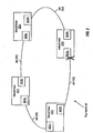
- FIG. 2 shows an example of a ring network.
- ring 20 includes network nodes 22(1), 22(2), 22(3), and 22(4) as well as links 24(1), 24(2), 24(3), and 24(4).
- each link 24(1)-24(4) is a physical or logical link (e.g., an aggregated link such as an Ether Channel); however, it is noted that in alternative embodiments, various other types of connections can be used to interconnect network nodes. For example, another network (e.g., having a ring, mesh, star, or tree topology) can be used to link two of the network nodes.
- another network e.g., having a ring, mesh, star, or tree topology
- ring 20 is shown as a complete ring in FIG. 2 , the techniques described herein can also be used in an incomplete ring (e.g., a daisy chain).
- network nodes 22(1)-22(4) are network devices such as switches, routers, and/or bridges that perform switching, routing, and/or bridging of packets.
- network nodes 22(1)-22(4) perform Ethernet switching.
- Network nodes 22(1)-22(4) can act as part of an access network that provides customers and/or end-users with access to a network (e.g., the Internet).
- a network e.g., the Internet
- one or more of the network nodes can be coupled to customer devices (e.g., routers and/or switches) and/or end-user devices such as hosts.
- network nodes 22(1)-22(4) can be coupled to network equipment that interconnects one or more access networks with a larger network.
- Each link 24(1)-24(4) provides bidirectional communication between a pair of network nodes.
- link 24(1) conveys packets between network nodes 22(1) and 22(2).
- link 24(2) conveys packets between network nodes 22(2) and 22(3)
- link 24(3) conveys packets between network nodes 22(3) and 22(4).
- Link 24(4) conveys packets between network nodes 22(1) and 22(4).
- network nodes 22(1)-22(4) implement a ring protocol, such as Rapid Ring Recovery (RRR).
- RRR Rapid Ring Recovery
- Such a ring protocol is implemented by exchanging ring protocol control packets between network nodes within the ring. These ring protocol control packets are used to detect continuity and connectivity within the ring as well as to detect failures within the ring. Ring behavior can be modified when failures are detected.
- Ring topology networks can be used within networks that are implemented using packet-based transport technologies. However, there are several situations involving ring topologies in which packet forwarding loops can arise. First, the ring itself forms a loop, and thus some sort of protocol must be employed to block this loop. Additionally, when several rings are connected, one or more switches are often included at the connection point in order to increase redundancy. The use of redundant switches potentially creates additional loops.
- the RRR ring protocol logically breaks the loop formed within ring 20.
- the RRR ring protocol causes ring 20 to behave as if there is a communication break within ring 20, making it unnecessary to implement another loop prevention protocol (such as spanning tree protocol) to break the loop within the ring.
- the RRR ring protocol causes this behavior by blocking data traffic at one or more points within the ring (e.g., in one embodiment, the protocol blocks all data traffic at one point within the ring; in another embodiment, the protocol blocks data traffic in different VLANs at different points within the ring).
- the RRR ring protocol exchanges ring protocol control packets among nodes in order to select a "designated port", to block the designated port when the loop is complete, and to unblock the designated port in response to detecting a failure within the ring. Before unblocking the designated port in response to a failure detected through the use of ring protocol control packets, however, the RRR protocol sends a special data packet around the ring. If the data packet does not successfully travel around the ring the network device that originated it, the RRR protocol determines that a data loop does not exist and unblocks the designated port.
- Each network node includes two ring ports that are configured to operate as part of ring 20 (it is noted that each network node can also include other ring ports that are part of another ring network).
- a ring port is an interface that is coupled to a link (physical or logical) and configured to send ring protocol control packets.
- a network node includes a pair of ring ports for each ring in which the network node participates. As shown in FIG.
- each network node includes a left (L) and a right (R) ring port: network node 22(1) includes ring ports 26(1L) and 26(1R); network node 22(2) includes ring ports 26(2L) and 26(2R); network node 22(3) includes ring ports 26(3L) and 26(3R); and network node 22(4) includes ring ports 26(4L) and 26(4R).
- Data packets that are received on one ring port and that are not destined for the receiving network node can be relayed via the other ring port in the pair.
- packets destined for the receiving network node are being sent to the receiving network node or a device that accesses the ring network via the receiving network node
- network node 22(1) receives a data packet (i.e., a non-ring protocol control packet) via port 26(1R)
- network node 22(1) can output that packet from port 26(1L).
- a data packet can also be destined to both the receiving network node as well as other network nodes, e.g., a broadcast packet. In this case, the receiving network node keeps a copy for itself and also sends a copy out via the other ring port in the pair.
- Ring protocol control packets are detected by ring ports and processed by the network node. For example, in response to receiving a ring protocol control packet via port 26(1L), ring port 26(1L) can generate an interrupt that causes a processor within network node 22(1) to handle the ring protocol control packet. In response to processing a ring protocol control packet, the network node can generate another ring protocol control packet, which may simply be a copy of the received ring protocol control packet, to send from the receiving ring port (e.g., in response to the ring protocol control packet) or from the paired ring port (e.g., if the ring protocol control packet is being sent around the ring).
- ring network 20 is an example of a network in which the control plane differs from the data plane.
- the loop prevention protocol in use within ring network 20 detects whether loops are present by sending control packets. If ring port 26(3L) is selected as the designated port and consequentially blocked (as indicated by the "X" in FIG. 2 ), the RRR protocol can periodically cause ring port 26(3L) to send a ring protocol control packet on link 24(2). If each ring protocol control packet is returned to ring port 26(3R) within a timeout period, it indicates that a communication loop is still present within ring network 20. Accordingly, the loop prevention protocol will continue to block the designated port.
- communication loops could also be detected by sending ring protocol control packets from ring port 26(3R) via link 24(3) and determining whether those ring protocol control packets are returned to ring port 26(3L) within a timeout period. (In RRR, a blocked ring port can still send and receive ring control packets.)
- the RRR protocol detects that the communication loop that was previously present within ring network 20 may no longer exist. However, the failure to return the ring protocol control packet within the timeout period could also be a result of a failure that only affects the control plane. In order to determine whether a data loop is still present, the RRR protocol will send a special data packet around the loop (e.g., by sending the data packet from designated port 26(3L) to ring port 26(3R) via link 24(2), or by sending the data packet from ring port 26(3R) to designated port 26(3L) via link 24(3).
- a special data packet around the loop e.g., by sending the data packet from designated port 26(3L) to ring port 26(3R) via link 24(2), or by sending the data packet from ring port 26(3R) to designated port 26(3L) via link 24(3).
- the RRR protocol initiates a timeout period (e.g., by starting a timer). If the data packet is received by network node 22(3) before the expiration of the timeout period (e.g., before the timer reaches a specified value), the RRR protocol determines that a communication loop is still present within ring network 20. Since a communication loop is still present, the RRR protocol will continue to block the designated port.
- a timeout period e.g., by starting a timer.
- the RRR protocol can safely decide that a data loop is indeed not present and the designated port 26(3L) will be unblocked
- the timeout period can be just a few milliseconds.
- the designated port when blocked, the designated port is typically not able to send and receive data traffic. Being blocked simply means that the designated port is in a particular logical state in which incoming and outgoing packets are dropped.
- the RRR protocol can, for example, create a temporary forwarding table entry corresponding to the special data packet. This forwarding table entry will establish a situation in which the special packet can be sent or received by the blocked port without being dropped.
- the RRR protocol can create a forwarding table entry indicating that a packet addressed to another ring port of the same network device should be forwarded from the designated port. The RRR protocol will then generate a special data packet addressed to the other ring port.
- the forwarding engine within the network node will then send that data packet from the designated port, based on the forwarding table entry.
- the RRR protocol then monitors the other ring port to detect whether the data packet successfully circumnavigates the network. Once the data packet has been received (or timeout period for receiving the data packet has expired), the RRR protocol can remove the temporary forwarding table entry.
- FIG. 3 shows a block diagram of a network node 32.
- network node 32 e.g., one of network nodes 12(1)-12(5) of FIG. 1 or network nodes 22(1)-22(4) of FIG. 2
- ports 34 and 36 as well as a control module 38, which in turn includes a loop prevention protocol module 40.
- Control module 38 can include forwarding and/or routing functionality.
- Control module 38 includes loop prevention module 40, which instantiates one or more instances of a protocol (such as a spanning tree protocol or RRR) in order to prevent communication loops. In some embodiments, there is one spanning tree instance per virtual local area network (VLAN).
- Control module 38 can be implemented in hardware, software, or a combination of hardware and software (e.g., all or part of control module 38 can be implemented in software that is executed by one or more processors within network node 32).
- Ports 34 and 36 are configured to send and receive packets.
- ports 34 and 36 are configured as ring ports.
- Ports 34 and 36 can be logical or physical ports.
- port 34 can be an aggregated port that includes several physical ports (aggregation can be provided by a protocol such as Link Aggregation Control Protocol (LACP) or Port Aggregation Protocol (PAgP)).
- LACP Link Aggregation Control Protocol
- PAgP Port Aggregation Protocol
- Loop prevention module 40 can send control and data packets via ports 34 and 36 in order to detect the presence or absence of communication loops within a network that includes network node 32. Loop prevention module 40 can also block and unblock one or more of ports 34 and 36. For example, loop prevention module 40 can update state information associated with the port to be blocked or unblocked, and this state information can in turn control how forwarding and routing decisions are made within network node 32. Loop prevention module 40 can temporarily unblock a blocked port (e.g., by creating a temporary forwarding table entry, as described above) when sending a special data packet to detect a communication loop.
- loop prevention module 40 When loop prevention module 40 detects a loop within a network topology, loop prevention module 40 selects a port to block in order to break the loop. In some embodiments, the port (if any, within network node 32) to block is selected by communicating with loop prevention modules in other network nodes.
- control module 38 When a control packet is received by one of ports 34 and 36, the receiving port notifies control module 38. This causes the control module to process the control packet. For example, if a loop prevention protocol control packet indicating a data loop is received, control module 38 can provide the control packet to loop prevention protocol module 40. Loop prevention protocol module 40 can then process the packet in order to determine whether a loop is present or absent as well as whether to block or unblock a port.
- Loop prevention protocol module 40 includes a control plane loop detection module 42 and a data plane loop detection module 44.
- Control plane loop detection module 42 is configured to use control packets to detect the presence or absence of a communication loop. For example, control plane loop detection module 42 can cause a control packet to be sent from network node 32 around a previously detected loop. If the control packet is returned to network node 32 within a timeout period, control plane loop detection module 42 determines that the loop is still present. If not, control plane loop detection module 42 determines that the loop is no longer present, at least with respect to the control plane.
- control plane loop detection module 42 determines that a previously-detected loop is no longer present, data plane loop detection module 44 will send a special data packet from network node 32 via the previously-detected loop in order to determine whether the loop is still present in the data plane. If the data packet is received by network node 32 within the timeout period, data plane loop detection module 44 will prevent loop prevention module 40 from unblocking a port, since the loop is still present. If the special data packet is not received by network node 32 within the timeout period, data plane loop detection module 44 will allow loop prevention module 40 to unblock the port, since the loop is no longer present in either the control or data plane.
- the loop prevention protocol is RRR
- ports 34 and 36 can be ring ports.
- RRR there are several types of ring protocol control packets, including fail packets, heal packets, loop complete packets, and loop broken packets. Receipt of one of these packets can cause loop prevention protocol module 40 to detect the presence or absence of a loop. If loop prevention protocol module 40 detects the absence of a loop, data plane loop detection module 44 will cause a data packet to be sent around the loop (e.g., by temporarily configuring the designated port so that the special data packet can be sent to or from the designated port) in order to confirm the absence of the loop.
- Fail packets are generated when a ring port detects that a link has gone down.
- the ring port that detects the failure generates a fail packet and sends the fail packet to a paired port.
- the paired port is either within the same network node as or directly coupled to the ring port that detects the failed link.
- a network node receives a fail packet, that node floods the fail packet to the paired ring port in the same ring as the receiving ring port.
- Use of fail packets allows ring ports to detect topology changes within the ring and react appropriately.
- Heal packets are generated as a pair of ring protocol control packets, such that each heal packet is sent in opposite directions on the ring network.
- a network node receives a heal packet, that node floods the heal packet from the ring port in the same ring as the receiving ring port.
- a ring port transitions from a failed state to a non-failed state and consequently generates a heal packet, a new data path may be created. This may create a temporary loop.
- Loop complete packets are originated by the designated port and sent to both the paired port (within the same network node as the designated port) and the link coupled to the designated port. These packets are used to detect whether there is a loop in the ring network. These packets are also used to elect a designated port and to identify whether the elected designated port is currently blocking.
- Loop broken packets are originated by the designated port and sent to both the paired port and the link. These packets are used to detect whether a loop has been restored, to elect a designated port, and to acknowledge receipt of a fail packet.
- FIG. 4 is a flowchart of a method of checking for a data loop in response to detecting a control plane disruption.
- This method can be performed by a control module (e.g., control module 38 of FIG. 3 ), which can include one or more forwarding engines (such forwarding engines can be distributed among several line cards) and/or route processors.
- the control module instantiates one or more instances of a loop prevention protocol.
- the method begins at 410, when the control module blocks a port in order to prevent a network loop.
- a blocked port is in a logical state in which the port cannot send or receive data packets. Any data packets sent to the blocked port will be dropped.
- the control module sends or receives a control packet in order to detect the presence or absence of the network loop.
- the control module (within the network node that includes the designated port) can send a control packet from the designated port to the other ring port within the same network node as the designated port. If the control packet is received at the other ring port before the expiration of a timeout period, the control module determines that the network loop is still present.
- the control module can receive a fail or heal packet, which respectively indicate that a network loop may be absent or present.
- the control module can send one or more BPDUs in order to detect the presence or absence of a network loop.
- the control module determines whether the network loop is still present in the control plane, as shown at 430. For example, if a control packet was sent around the network loop at 420, the control module determines that the network loop is still present if the control packet successfully circumnavigates the network loop within a timeout period.
- control module attempts to send a special data packet via the network loop, as shown at 440.
- control module may temporarily unblock the blocked port for special data packets in order to send and/or receive this data packet.
- the control module determines that the network loop is still present in the data plane. Accordingly, the control module does not unblock the port that was originally blocked at 410. The control module can continue to try to detect the presence or absence of the network loop in the control plane (e.g., by repeating operations 420 and 430) at this point. The control module can additionally generate an error indication (e.g., by logging an error message, causing an error indicator light to light up or blink, by sending an email or instant message to an administrator, or the like) in this situation, since there appears to be a disruption in the control plane but not the data plane.
- an error indication e.g., by logging an error message, causing an error indicator light to light up or blink, by sending an email or instant message to an administrator, or the like
- the control module unblocks the port (which was originally blocked at 410), as shown at 460.
- FIG. 5 shows a block diagram of a network node 32 (e.g., network node 32 of FIG. 3 ).
- network node 32 includes a number of line cards (line cards 902(1)-902(N)) that are communicatively coupled to a forwarding engine 910 and a route processor 900 via a data bus 930 and a result bus 940.
- Line cards 902(1)-902(N) include a number of port processors 950(1,1)-950(N,N) which are controlled by port processor controllers 960(1)-960(N).
- One or more port processors 950(1,1.)-950(N,N) can be configured as ring ports by assigning ring identifiers to those port processors.
- forwarding engine 910 and route processor 900 are not only coupled to one another via data bus 930 and result bus 940, but are also communicatively coupled to one another by a communications link 970. It is noted that in alternative embodiments, each line card can include a forwarding engine. It is noted that route processor 900 and forwarding engine 910 implement the functionality of the control module 38 shown in FIG. 3 . The functionality of loop prevention module 40 can be implemented in route processor 900, as shown in FIG. 5 .
- a packet When a packet is received, the packet is identified and analyzed by a network device such as network node 32 in the following manner, according to embodiments of the present invention.
- a packet (or some or all of its control information) is sent from the one of port processors 950(1,1)-950(N,N) at which the packet was received to one or more of those devices coupled to data bus 930 (e.g., others of port processors 950(1,1)-950(N,N), forwarding engine 910 and/or route processor 900). Handling of the packet can be determined, for example, by forwarding engine 910. For example, forwarding engine 910 may determine that the packet should be forwarded to one or more of port processors 950(1,1)-950(N,N).
- one or more (e.g., a pair) of port processors 950(1,1)-950(N,N) can be blocked by loop prevention module 40.
- port processors 950(1,1)-950(N,N) can send and receive loop prevention protocol control packets as well as special data packets generated by loop prevention module 40 to confirm whether a network loop is present in the data plane. If loop prevention module 40 detects that a network loop is no longer present in the control plane, loop prevention module 40 can send such a special data packet before unblocking any previously-blocked port.
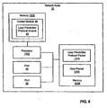
- FIG. 6 is another block diagram of network node 32 (e.g., network node 32 of FIG. 3 ), which illustrates how loop prevention protocol module 40 can be implemented in software.
- network node 32 includes one or more processors 1002 (e.g., microprocessors, PLDs (Programmable Logic Devices), or ASICs (Application Specific Integrated Circuits)) configured to execute program instructions stored in memory 1006.
- processors 1002 e.g., microprocessors, PLDs (Programmable Logic Devices), or ASICs (Application Specific Integrated Circuits)
- Memory 1006 can include various types of RAM (Random Access Memory), ROM (Read Only memory), Flash memory, MEMS (Micro Electro-Mechanical Systems) memory, and the like.
- Processor 1002 and memory 1006 can be included in a port processor (e.g., port processors 930(1,1)-950(N,N) of FIG.
- Processor 1002 and memory 1006 are coupled to send and receive data and control signals by a bus or other interconnect.
- Network node 32 also includes several ports, such as ports 34 and 36. Each of these ports can be coupled to another network node via a link. In response to receiving a packet (e.g., such as a loop prevention protocol packet 1010), ports 34 and 36 can store copies of the received packets in memory 1008. Processor 1002, ports 34 and 36, and memory 1008 are coupled to send and receive data and control signals by a bus or other interconnect.
- a packet e.g., such as a loop prevention protocol packet 1010
- Processor 1002 ports 34 and 36, and memory 1008 are coupled to send and receive data and control signals by a bus or other interconnect.
- program instructions executable to implement control module 38 are stored in memory 1006.
- the program instructions and data implementing loop prevention protocol module 40 can be stored on various computer readable media such as memory 1006.
- such software is stored on a computer readable medium such as a CD (Compact Disc), DVD (Digital Versatile Disc), hard disk, optical disk, tape device, floppy disk, and the like).
- the instructions and data implementing loop prevention protocol module 40 are loaded into memory 1006 from the other computer readable medium.
- the instructions and/or data implementing control module 38 can also be transferred to network node 12(1) for storage in memory 1006 via a network such as the Internet or upon a carrier medium.
- a computer readable medium is a carrier medium such as a network and/or a wireless link upon which signals such as electrical, electromagnetic, or digital signals, on which the data and instructions implementing loop prevention protocol module 40 are encoded, are conveyed.
- Embodiments of the present invention can be used in the field of networking.
Landscapes
- Engineering & Computer Science (AREA)
- Computer Networks & Wireless Communication (AREA)
- Signal Processing (AREA)
- Small-Scale Networks (AREA)
- Constituent Portions Of Griding Lathes, Driving, Sensing And Control (AREA)
Claims (14)
- Verfahren, das umfasst:im Ansprechen auf das Ermitteln (430) einer Unterbrechung in einer Netzwerkschleife in einer Steuerungsebene eines Netzwerks, Senden (440) eines speziellen Datenpakets; undFreigeben (460) eines Ports, wenn es dem speziellen Datenpaket misslingt, die Netzwerkschleife in einer Datenebene des Netzwerks zu umgehen; undwobei der Port im Ansprechen auf das Ermitteln der Netzwerkschleife in der Steuerungsebene blockiert wurde; undVerhindern, dass der Port freigegeben wird, wenn das spezielle Datenpaket die Netzwerkschleife in der Datenebene erfolgreich umgeht.
- Verfahren nach Anspruch 1, wobei das Blockieren des Ports von einer Instanz eines Spanning Tree Protocol (Spannbaum-Protokoll) durchgeführt wird.
- Verfahren nach Anspruch 1, wobei das Blockieren des Ports von einer Instanz eines Ringprotokolls durchgeführt wird.
- Verfahren nach Anspruch 1, wobei das Senden des speziellen Datenpakets das temporäre Konfigurieren des Ports zum Senden des speziellen Datenpakets von dem Port umfasst.
- Verfahren nach Anspruch 4, wobei das temporäre Konfigurieren des Ports das Erzeugen eines Vorwärtstabelleneintrags, der dem speziellen Datenpaket entspricht, umfasst.
- Verfahren nach Anspruch 1, das des Weiteren umfasst:Ermitteln (450), dass das spezielle Datenpaket die Netzwerkschleife in der Datenebene erfolgreich umgangen hat, wenn eine Netzwerkvorrichtung das spezielle Datenpaket innerhalb einer Timeout-Periode empfängt, wobei die Netzwerkvorrichtung das spezielle Datenpaket sendete, und wobei die Netzwerkvorrichtung den Port aufweist.
- Netzwerkknoten (32) zur Verwendung in einem Netzwerk mit einer Steuerungsebene und einer Datenebene, der aufweist:ein Schleifenverhinderungs-Modul (40), wobei das Schleifenverhinderungs-Modul (40) ein Steuerungsebene-Schleifenermittlungs-Modul (42) und ein Datenebene-Schleifenermittlungs-Modul (44) aufweist, undeinen Port (34, 36), der an das Schleifenverhinderungs-Modul (40) gekoppelt ist, wobeidas Schleifenverhinderungs-Modul (40) so konfiguriert ist, dass es den Port (34, 36) im Ansprechen auf die Ermittlung einer Netzwerkschleife in einer Steuerungsebene des Netzwerks durch das Steuerungsebene-Schleifenermittlungs-Modul (42) blockiert, und wobei das Datenebene-Schleifenermittlungs-Modul (44) so konfiguriert ist, dass es ein spezielles Datenpaket im Ansprechen auf die Ermittlung einer Unterbrechung in der Steuerungsebene durch das Steuerungsebene-Schleifenermittlungs-Modul (42) sendet, wobei das Datenebene-Schleifenermittlungs-Modul (42) so konfiguriert ist, dass es den Port freigibt, wenn es dem speziellen Datenpaket misslingt, die Netzwerkschleife in einer Datenebene des Netzwerks zu umgehen; unddas Datenebene-Schleifenermittlungs-Modul (42) so konfiguriert ist, dass es verhindert, dass der Port (34, 36) freigegeben wird, wenn das spezielle Datenpaket die Netzwerkschleife in der Datenebene erfolgreich umgeht.
- Netzwerkknoten (32) nach Anspruch 7, wobei das Schleifenverhinderungs-Modul (40) ein Spanning Tree Protocol (Spannbaum-Protokoll) implementiert.
- Netzwerkknoten (32) nach Anspruch 7, wobei das Schleifenverhinderungs-Modul (40) ein Ringprotokoll implementiert.
- Netzwerkknoten (32) nach Anspruch 7, wobei das Datenebene-Schleifenermittlungs-Modul (44) so konfiguriert ist, dass es den blockierten Port temporär so konfiguriert, dass er das spezielle Datenpaket von dem Port sendet.
- Netzwerkknoten (32) nach Anspruch 10, wobei das Datenebene-Schleifenermittlungs-Modul (44) so konfiguriert ist, dass es den blockierten Port durch Erzeugen eines Vorwärtstabellen-Eintrags, der dem speziellen Datenpaket entspricht, temporär konfiguriert.
- Netzwerkknoten (32) nach Anspruch 7, wobei das Datenebene-Schleifenermittlungs-Modul (44) so konfiguriert ist, dass es ermittelt, das das spezielle Datenpaket die Netzwerkschleife in der Datenebene erfolgreich umgangen hat, wenn der Netzwerkknoten das spezielle Datenpaket innerhalb einer Timeout-Periode empfängt.
- Netzwerkknoten (32) nach Anspruch 12, wobei das Datenebene-Schleifenermittlungs-Modul (44) so konfiguriert ist, dass es dem Port erlaubt, freigegeben zu werden, wenn das spezielle Datenpaket die Netzwerkschleife in der Datenebene innerhalb der Timeout-Periode nicht umgeht.
- System, das aufweist:ein Netzwerk mit einer Vielzahl von Netzwerkknoten, die wenigstens einen Netzwerkknoten nach einem der Ansprüche 7 bis 13 aufweisen.
Applications Claiming Priority (2)
| Application Number | Priority Date | Filing Date | Title |
|---|---|---|---|
| US11/336,704 US7911938B2 (en) | 2006-01-20 | 2006-01-20 | System and method for preventing loops in the presence of control plane failures |
| PCT/US2007/001491 WO2007084696A2 (en) | 2006-01-20 | 2007-01-18 | System and method for preventing loops in the presence of control plane failures |
Publications (2)
| Publication Number | Publication Date |
|---|---|
| EP1994694A2 EP1994694A2 (de) | 2008-11-26 |
| EP1994694B1 true EP1994694B1 (de) | 2011-03-09 |
Family
ID=38285442
Family Applications (1)
| Application Number | Title | Priority Date | Filing Date |
|---|---|---|---|
| EP07718108A Not-in-force EP1994694B1 (de) | 2006-01-20 | 2007-01-18 | System und verfahren zur vermeidung von schleifen bei defekten auf steuerungsebene |
Country Status (5)
| Country | Link |
|---|---|
| US (1) | US7911938B2 (de) |
| EP (1) | EP1994694B1 (de) |
| AT (1) | ATE501570T1 (de) |
| DE (1) | DE602007013011D1 (de) |
| WO (1) | WO2007084696A2 (de) |
Families Citing this family (42)
| Publication number | Priority date | Publication date | Assignee | Title |
|---|---|---|---|---|
| US8325629B2 (en) | 2005-07-15 | 2012-12-04 | Cisco Technology, Inc. | System and method for assuring the operation of network devices in bridged networks |
| US20070280238A1 (en) * | 2006-05-30 | 2007-12-06 | Martin Lund | Method and system for passive loop detection and prevention in a packet network switch |
| US7653057B1 (en) * | 2006-11-30 | 2010-01-26 | World Wide Packets, Inc. | Preventing forwarding of a packet to a control plane |
| US7898945B2 (en) * | 2006-12-26 | 2011-03-01 | Roland Corporation | System, apparatus, and method for multimedia transmission |
| US20090016214A1 (en) * | 2007-07-12 | 2009-01-15 | Allied Telesis Holdings K.K. | Method and system for network recovery from multiple link failures |
| EP2020782A1 (de) * | 2007-08-03 | 2009-02-04 | Nokia Siemens Networks Oy | Verfahren und Vorrichtung zum Schutz eines Ringes und System mit einer derartigen Vorrichtung |
| US7944815B2 (en) * | 2008-02-14 | 2011-05-17 | Allied Telesis Holdings K.K. | System and method for network recovery from multiple link failures |
| CN101562552B (zh) * | 2009-05-27 | 2011-09-14 | 华为技术有限公司 | 一种虚拟专用局域网环路检测的方法、系统和设备 |
| US20100302967A1 (en) * | 2009-05-29 | 2010-12-02 | Electronics And Telecommunications Research Institute | Method and apparatus for measuring network delay in ethernet ring network |
| IL199146A0 (en) * | 2009-06-04 | 2010-04-29 | Eci Telecom Ltd | Method and network for combined protection of ethernet traffic |
| TWI403195B (zh) * | 2009-09-16 | 2013-07-21 | Ralink Technology Corp | 無線網路鏈結叢集之方法及系統 |
| EP2375652B1 (de) * | 2010-03-29 | 2018-05-30 | Etherwan Systems, Inc. | Redundantes Netzwerkverbindungssystem für Vorrichtungen mit Kaskadennetzwerkkapazität und auf das System angewandte Verfahren |
| CN102739466B (zh) * | 2011-04-13 | 2017-10-17 | 中兴通讯股份有限公司 | 一种设置以太网节点检测帧超时时长的方法及系统 |
| US9258234B1 (en) | 2012-12-28 | 2016-02-09 | Juniper Networks, Inc. | Dynamically adjusting liveliness detection intervals for periodic network communications |
| TW201431320A (zh) * | 2013-01-24 | 2014-08-01 | Accton Technology Corp | 迴路偵測的方法及網路裝置 |
| US9553796B2 (en) | 2013-03-15 | 2017-01-24 | Cisco Technology, Inc. | Cycle-free multi-topology routing |
| US9655232B2 (en) | 2013-11-05 | 2017-05-16 | Cisco Technology, Inc. | Spanning tree protocol (STP) optimization techniques |
| US9374294B1 (en) | 2013-11-05 | 2016-06-21 | Cisco Technology, Inc. | On-demand learning in overlay networks |
| US9769078B2 (en) | 2013-11-05 | 2017-09-19 | Cisco Technology, Inc. | Dynamic flowlet prioritization |
| US10778584B2 (en) | 2013-11-05 | 2020-09-15 | Cisco Technology, Inc. | System and method for multi-path load balancing in network fabrics |
| US9502111B2 (en) | 2013-11-05 | 2016-11-22 | Cisco Technology, Inc. | Weighted equal cost multipath routing |
| US9674086B2 (en) | 2013-11-05 | 2017-06-06 | Cisco Technology, Inc. | Work conserving schedular based on ranking |
| US20150236911A1 (en) * | 2014-02-18 | 2015-08-20 | Aruba Networks, Inc. | Detecting characteristics of a data path loop on a network |
| JP6388434B2 (ja) * | 2014-07-18 | 2018-09-12 | アライドテレシスホールディングス株式会社 | ネットワーク機器、通信方法、プログラム、記録媒体 |
| US9769017B1 (en) * | 2014-09-26 | 2017-09-19 | Juniper Networks, Inc. | Impending control plane disruption indication using forwarding plane liveliness detection protocols |
| US10454851B2 (en) * | 2015-04-16 | 2019-10-22 | Cisco Technology, Inc. | Optimized link failure convergence for resilient ethernet protocol networks |
| US9843495B2 (en) * | 2015-08-26 | 2017-12-12 | Fujitsu Limited | Seamless migration from rapid spanning tree protocol to ethernet ring protection switching protocol |
| US10374936B2 (en) | 2015-12-30 | 2019-08-06 | Juniper Networks, Inc. | Reducing false alarms when using network keep-alive messages |
| US10050804B2 (en) * | 2016-06-01 | 2018-08-14 | Pluribus Networks, Inc. | Loop-free fabric utilizing distributed address and port tables |
| US10397085B1 (en) | 2016-06-30 | 2019-08-27 | Juniper Networks, Inc. | Offloading heartbeat responses message processing to a kernel of a network device |
| US9923731B1 (en) * | 2016-09-12 | 2018-03-20 | Fujitsu Limited | Seamless migration from multiple spanning tree protocol to ethernet ring protection switching protocol |
| US10432578B2 (en) | 2016-09-27 | 2019-10-01 | Cisco Technology, Inc. | Client address based forwarding of dynamic host configuration protocol response packets |
| US10454882B2 (en) | 2017-06-30 | 2019-10-22 | Cisco Technology, Inc. | DHCP in layer-3 overlay with anycast address support and network address transparency |
| US11025537B2 (en) * | 2017-12-04 | 2021-06-01 | Is5 Communications, Inc. | Multiple RSTP domain separation |
| TWI643520B (zh) | 2017-12-15 | 2018-12-01 | 智易科技股份有限公司 | 適用於網狀網路的網路裝置及應用其之控制方法 |
| CN109284189A (zh) * | 2018-09-06 | 2019-01-29 | 福建星瑞格软件有限公司 | 一种批量任务超时高效触发方法及系统 |
| US11750441B1 (en) | 2018-09-07 | 2023-09-05 | Juniper Networks, Inc. | Propagating node failure errors to TCP sockets |
| JP7238535B2 (ja) * | 2019-03-27 | 2023-03-14 | オムロン株式会社 | ネットワーク管理装置、管理方法、管理プログラムおよび記録媒体 |
| CN112242914B (zh) * | 2019-07-18 | 2023-10-03 | 华为技术有限公司 | 网络异常根因定位方法、装置及系统、计算机存储介质 |
| US20210306252A1 (en) * | 2020-03-25 | 2021-09-30 | Hewlett Packard Enterprise Development Lp | Loop avoidance protocol |
| CN113938421B (zh) * | 2021-11-18 | 2023-02-28 | 浪潮思科网络科技有限公司 | 一种基于Force-up功能的防环机制实现方法、设备及介质 |
| CN117395343B (zh) * | 2023-09-20 | 2026-03-20 | 南京莱斯电子设备有限公司 | 一种基于ed137c标准的民航管制通信监听系统 |
Family Cites Families (11)
| Publication number | Priority date | Publication date | Assignee | Title |
|---|---|---|---|---|
| US6081512A (en) * | 1997-06-30 | 2000-06-27 | Sun Microsystems, Inc. | Spanning tree support in a high performance network device |
| US7463591B1 (en) * | 2001-06-25 | 2008-12-09 | Juniper Networks, Inc. | Detecting data plane liveliness of a label-switched path |
| US6766482B1 (en) * | 2001-10-31 | 2004-07-20 | Extreme Networks | Ethernet automatic protection switching |
| US6717922B2 (en) | 2002-03-04 | 2004-04-06 | Foundry Networks, Inc. | Network configuration protocol and method for rapid traffic recovery and loop avoidance in ring topologies |
| US20040105455A1 (en) | 2002-08-29 | 2004-06-03 | Seaman Michael John | Automatic edge port and one way connectivity detection with rapid reconfiguration for shared media in spanning tree configured bridged Local Area Networks |
| US7355965B2 (en) * | 2003-05-06 | 2008-04-08 | Overture Networks, Inc. | Apparatus and method for rapid detection of unidirectional breaks in a network ring |
| CA2566005C (en) * | 2003-05-06 | 2009-12-15 | Overture Networks, Inc. | Protected switching ring |
| US7983173B2 (en) | 2004-05-10 | 2011-07-19 | Cisco Technology, Inc. | System and method for detecting link failures |
| JP2006033275A (ja) | 2004-07-14 | 2006-02-02 | Fujitsu Ltd | ループフレーム検知装置およびループフレーム検知方法 |
| US7408883B2 (en) | 2004-09-01 | 2008-08-05 | Nettest, Inc. | Apparatus and method for performing a loopback test in a communication system |
| US7920548B2 (en) * | 2005-08-18 | 2011-04-05 | Hong Kong Applied Science And Technology Research Institute Co. Ltd. | Intelligent switching for secure and reliable voice-over-IP PBX service |
-
2006
- 2006-01-20 US US11/336,704 patent/US7911938B2/en active Active
-
2007
- 2007-01-18 WO PCT/US2007/001491 patent/WO2007084696A2/en not_active Ceased
- 2007-01-18 AT AT07718108T patent/ATE501570T1/de not_active IP Right Cessation
- 2007-01-18 EP EP07718108A patent/EP1994694B1/de not_active Not-in-force
- 2007-01-18 DE DE602007013011T patent/DE602007013011D1/de active Active
Also Published As
| Publication number | Publication date |
|---|---|
| WO2007084696A2 (en) | 2007-07-26 |
| DE602007013011D1 (de) | 2011-04-21 |
| US20070171814A1 (en) | 2007-07-26 |
| WO2007084696A3 (en) | 2007-10-25 |
| EP1994694A2 (de) | 2008-11-26 |
| US7911938B2 (en) | 2011-03-22 |
| ATE501570T1 (de) | 2011-03-15 |
Similar Documents
| Publication | Publication Date | Title |
|---|---|---|
| EP1994694B1 (de) | System und verfahren zur vermeidung von schleifen bei defekten auf steuerungsebene | |
| US8411690B2 (en) | Preventing data traffic connectivity between endpoints of a network segment | |
| US7778205B2 (en) | System and method for implementing virtual ports within ring networks | |
| US7233991B2 (en) | Self-healing tree network | |
| US8213296B2 (en) | Link aggregation protection | |
| EP2352253B1 (de) | Verfahren und vorrichtung für den schutz einer verbindungsbündelungsgruppe eines ethernetrings | |
| US8345699B2 (en) | System and method for enabling a remote instance of a loop avoidance protocol | |
| US8699380B2 (en) | Port table flushing in ethernet networks | |
| CN101060485B (zh) | 拓扑改变报文的处理方法和处理装置 | |
| EP1878168B1 (de) | System und verfahren zur implementierung von reflektoranschlüssen in hierarchischen netzwerken | |
| EP1625705A2 (de) | Geschützter vermittlungsring | |
| US8687523B2 (en) | System and method for integrating ring-protocol-compatible devices into network configurations that also include non-ring-protocol compatible devices | |
| US11516119B2 (en) | System, method, and device for communication between network segments | |
| CN103053139B (zh) | 一种报文处理方法及系统 | |
| CN101227371B (zh) | 同级交换机设备间的备份切换方法和装置 | |
| CN100546303C (zh) | 能够避免突发的生成树协议 | |
| CN103490921B (zh) | 网络保护方法、装置、下环节点及系统 | |
| CN112995002B (zh) | 一种交换机环网的设计方法、交换机及存储介质 | |
| US9065756B2 (en) | System and method for providing fast and efficient flushing of a forwarding database in a network processor | |
| CN101557333A (zh) | 一种双归属组网中环路故障的处理方法及节点设备 | |
| CN104579736A (zh) | 一种环路数据传输方法及节点设备 | |
| WO2017148093A1 (zh) | 一种节点设备及环网切换方法 | |
| JP2005341128A (ja) | レイヤ2伝送装置およびレイヤ2伝送装置の制御方法 |
Legal Events
| Date | Code | Title | Description |
|---|---|---|---|
| PUAI | Public reference made under article 153(3) epc to a published international application that has entered the european phase |
Free format text: ORIGINAL CODE: 0009012 |
|
| 17P | Request for examination filed |
Effective date: 20080731 |
|
| AK | Designated contracting states |
Kind code of ref document: A2 Designated state(s): AT BE BG CH CY CZ DE DK EE ES FI FR GB GR HU IE IS IT LI LT LU LV MC NL PL PT RO SE SI SK TR |
|
| 17Q | First examination report despatched |
Effective date: 20090702 |
|
| GRAP | Despatch of communication of intention to grant a patent |
Free format text: ORIGINAL CODE: EPIDOSNIGR1 |
|
| DAX | Request for extension of the european patent (deleted) | ||
| GRAS | Grant fee paid |
Free format text: ORIGINAL CODE: EPIDOSNIGR3 |
|
| GRAA | (expected) grant |
Free format text: ORIGINAL CODE: 0009210 |
|
| AK | Designated contracting states |
Kind code of ref document: B1 Designated state(s): AT BE BG CH CY CZ DE DK EE ES FI FR GB GR HU IE IS IT LI LT LU LV MC NL PL PT RO SE SI SK TR |
|
| REG | Reference to a national code |
Ref country code: GB Ref legal event code: FG4D |
|
| REG | Reference to a national code |
Ref country code: CH Ref legal event code: EP |
|
| REG | Reference to a national code |
Ref country code: IE Ref legal event code: FG4D |
|
| REF | Corresponds to: |
Ref document number: 602007013011 Country of ref document: DE Date of ref document: 20110421 Kind code of ref document: P |
|
| REG | Reference to a national code |
Ref country code: DE Ref legal event code: R096 Ref document number: 602007013011 Country of ref document: DE Effective date: 20110421 |
|
| REG | Reference to a national code |
Ref country code: NL Ref legal event code: VDEP Effective date: 20110309 |
|
| PG25 | Lapsed in a contracting state [announced via postgrant information from national office to epo] |
Ref country code: ES Free format text: LAPSE BECAUSE OF FAILURE TO SUBMIT A TRANSLATION OF THE DESCRIPTION OR TO PAY THE FEE WITHIN THE PRESCRIBED TIME-LIMIT Effective date: 20110620 Ref country code: GR Free format text: LAPSE BECAUSE OF FAILURE TO SUBMIT A TRANSLATION OF THE DESCRIPTION OR TO PAY THE FEE WITHIN THE PRESCRIBED TIME-LIMIT Effective date: 20110610 Ref country code: LT Free format text: LAPSE BECAUSE OF FAILURE TO SUBMIT A TRANSLATION OF THE DESCRIPTION OR TO PAY THE FEE WITHIN THE PRESCRIBED TIME-LIMIT Effective date: 20110309 Ref country code: LV Free format text: LAPSE BECAUSE OF FAILURE TO SUBMIT A TRANSLATION OF THE DESCRIPTION OR TO PAY THE FEE WITHIN THE PRESCRIBED TIME-LIMIT Effective date: 20110309 Ref country code: SE Free format text: LAPSE BECAUSE OF FAILURE TO SUBMIT A TRANSLATION OF THE DESCRIPTION OR TO PAY THE FEE WITHIN THE PRESCRIBED TIME-LIMIT Effective date: 20110309 |
|
| LTIE | Lt: invalidation of european patent or patent extension |
Effective date: 20110309 |
|
| PG25 | Lapsed in a contracting state [announced via postgrant information from national office to epo] |
Ref country code: SI Free format text: LAPSE BECAUSE OF FAILURE TO SUBMIT A TRANSLATION OF THE DESCRIPTION OR TO PAY THE FEE WITHIN THE PRESCRIBED TIME-LIMIT Effective date: 20110309 Ref country code: CY Free format text: LAPSE BECAUSE OF FAILURE TO SUBMIT A TRANSLATION OF THE DESCRIPTION OR TO PAY THE FEE WITHIN THE PRESCRIBED TIME-LIMIT Effective date: 20110309 Ref country code: AT Free format text: LAPSE BECAUSE OF FAILURE TO SUBMIT A TRANSLATION OF THE DESCRIPTION OR TO PAY THE FEE WITHIN THE PRESCRIBED TIME-LIMIT Effective date: 20110309 Ref country code: BG Free format text: LAPSE BECAUSE OF FAILURE TO SUBMIT A TRANSLATION OF THE DESCRIPTION OR TO PAY THE FEE WITHIN THE PRESCRIBED TIME-LIMIT Effective date: 20110609 Ref country code: NL Free format text: LAPSE BECAUSE OF FAILURE TO SUBMIT A TRANSLATION OF THE DESCRIPTION OR TO PAY THE FEE WITHIN THE PRESCRIBED TIME-LIMIT Effective date: 20110309 Ref country code: FI Free format text: LAPSE BECAUSE OF FAILURE TO SUBMIT A TRANSLATION OF THE DESCRIPTION OR TO PAY THE FEE WITHIN THE PRESCRIBED TIME-LIMIT Effective date: 20110309 |
|
| PG25 | Lapsed in a contracting state [announced via postgrant information from national office to epo] |
Ref country code: BE Free format text: LAPSE BECAUSE OF FAILURE TO SUBMIT A TRANSLATION OF THE DESCRIPTION OR TO PAY THE FEE WITHIN THE PRESCRIBED TIME-LIMIT Effective date: 20110309 |
|
| PG25 | Lapsed in a contracting state [announced via postgrant information from national office to epo] |
Ref country code: EE Free format text: LAPSE BECAUSE OF FAILURE TO SUBMIT A TRANSLATION OF THE DESCRIPTION OR TO PAY THE FEE WITHIN THE PRESCRIBED TIME-LIMIT Effective date: 20110309 Ref country code: PT Free format text: LAPSE BECAUSE OF FAILURE TO SUBMIT A TRANSLATION OF THE DESCRIPTION OR TO PAY THE FEE WITHIN THE PRESCRIBED TIME-LIMIT Effective date: 20110711 |
|
| PG25 | Lapsed in a contracting state [announced via postgrant information from national office to epo] |
Ref country code: IS Free format text: LAPSE BECAUSE OF FAILURE TO SUBMIT A TRANSLATION OF THE DESCRIPTION OR TO PAY THE FEE WITHIN THE PRESCRIBED TIME-LIMIT Effective date: 20110709 Ref country code: SK Free format text: LAPSE BECAUSE OF FAILURE TO SUBMIT A TRANSLATION OF THE DESCRIPTION OR TO PAY THE FEE WITHIN THE PRESCRIBED TIME-LIMIT Effective date: 20110309 Ref country code: RO Free format text: LAPSE BECAUSE OF FAILURE TO SUBMIT A TRANSLATION OF THE DESCRIPTION OR TO PAY THE FEE WITHIN THE PRESCRIBED TIME-LIMIT Effective date: 20110309 Ref country code: CZ Free format text: LAPSE BECAUSE OF FAILURE TO SUBMIT A TRANSLATION OF THE DESCRIPTION OR TO PAY THE FEE WITHIN THE PRESCRIBED TIME-LIMIT Effective date: 20110309 |
|
| PLBE | No opposition filed within time limit |
Free format text: ORIGINAL CODE: 0009261 |
|
| STAA | Information on the status of an ep patent application or granted ep patent |
Free format text: STATUS: NO OPPOSITION FILED WITHIN TIME LIMIT |
|
| 26N | No opposition filed |
Effective date: 20111212 |
|
| PG25 | Lapsed in a contracting state [announced via postgrant information from national office to epo] |
Ref country code: PL Free format text: LAPSE BECAUSE OF FAILURE TO SUBMIT A TRANSLATION OF THE DESCRIPTION OR TO PAY THE FEE WITHIN THE PRESCRIBED TIME-LIMIT Effective date: 20110309 Ref country code: DK Free format text: LAPSE BECAUSE OF FAILURE TO SUBMIT A TRANSLATION OF THE DESCRIPTION OR TO PAY THE FEE WITHIN THE PRESCRIBED TIME-LIMIT Effective date: 20110309 |
|
| REG | Reference to a national code |
Ref country code: DE Ref legal event code: R097 Ref document number: 602007013011 Country of ref document: DE Effective date: 20111212 |
|
| PG25 | Lapsed in a contracting state [announced via postgrant information from national office to epo] |
Ref country code: IT Free format text: LAPSE BECAUSE OF FAILURE TO SUBMIT A TRANSLATION OF THE DESCRIPTION OR TO PAY THE FEE WITHIN THE PRESCRIBED TIME-LIMIT Effective date: 20110309 |
|
| PG25 | Lapsed in a contracting state [announced via postgrant information from national office to epo] |
Ref country code: MC Free format text: LAPSE BECAUSE OF NON-PAYMENT OF DUE FEES Effective date: 20120131 |
|
| REG | Reference to a national code |
Ref country code: CH Ref legal event code: PL |
|
| REG | Reference to a national code |
Ref country code: IE Ref legal event code: MM4A |
|
| PG25 | Lapsed in a contracting state [announced via postgrant information from national office to epo] |
Ref country code: CH Free format text: LAPSE BECAUSE OF NON-PAYMENT OF DUE FEES Effective date: 20120131 Ref country code: LI Free format text: LAPSE BECAUSE OF NON-PAYMENT OF DUE FEES Effective date: 20120131 |
|
| PG25 | Lapsed in a contracting state [announced via postgrant information from national office to epo] |
Ref country code: IE Free format text: LAPSE BECAUSE OF NON-PAYMENT OF DUE FEES Effective date: 20120118 |
|
| PG25 | Lapsed in a contracting state [announced via postgrant information from national office to epo] |
Ref country code: TR Free format text: LAPSE BECAUSE OF FAILURE TO SUBMIT A TRANSLATION OF THE DESCRIPTION OR TO PAY THE FEE WITHIN THE PRESCRIBED TIME-LIMIT Effective date: 20110309 |
|
| PG25 | Lapsed in a contracting state [announced via postgrant information from national office to epo] |
Ref country code: LU Free format text: LAPSE BECAUSE OF NON-PAYMENT OF DUE FEES Effective date: 20120118 |
|
| PG25 | Lapsed in a contracting state [announced via postgrant information from national office to epo] |
Ref country code: HU Free format text: LAPSE BECAUSE OF FAILURE TO SUBMIT A TRANSLATION OF THE DESCRIPTION OR TO PAY THE FEE WITHIN THE PRESCRIBED TIME-LIMIT Effective date: 20070118 |
|
| REG | Reference to a national code |
Ref country code: FR Ref legal event code: PLFP Year of fee payment: 9 |
|
| REG | Reference to a national code |
Ref country code: FR Ref legal event code: PLFP Year of fee payment: 10 |
|
| REG | Reference to a national code |
Ref country code: FR Ref legal event code: PLFP Year of fee payment: 11 |
|
| REG | Reference to a national code |
Ref country code: FR Ref legal event code: PLFP Year of fee payment: 12 |
|
| PGFP | Annual fee paid to national office [announced via postgrant information from national office to epo] |
Ref country code: DE Payment date: 20200129 Year of fee payment: 14 Ref country code: GB Payment date: 20200127 Year of fee payment: 14 |
|
| PGFP | Annual fee paid to national office [announced via postgrant information from national office to epo] |
Ref country code: FR Payment date: 20200127 Year of fee payment: 14 |
|
| REG | Reference to a national code |
Ref country code: DE Ref legal event code: R119 Ref document number: 602007013011 Country of ref document: DE |
|
| GBPC | Gb: european patent ceased through non-payment of renewal fee |
Effective date: 20210118 |
|
| PG25 | Lapsed in a contracting state [announced via postgrant information from national office to epo] |
Ref country code: FR Free format text: LAPSE BECAUSE OF NON-PAYMENT OF DUE FEES Effective date: 20210131 |
|
| PG25 | Lapsed in a contracting state [announced via postgrant information from national office to epo] |
Ref country code: GB Free format text: LAPSE BECAUSE OF NON-PAYMENT OF DUE FEES Effective date: 20210118 Ref country code: DE Free format text: LAPSE BECAUSE OF NON-PAYMENT OF DUE FEES Effective date: 20210803 |
|
| P01 | Opt-out of the competence of the unified patent court (upc) registered |
Effective date: 20230525 |