EP1994854A2 - Dispositif de nettoyage pour circuit de transmission de mouvement - Google Patents
Dispositif de nettoyage pour circuit de transmission de mouvement Download PDFInfo
- Publication number
- EP1994854A2 EP1994854A2 EP08008558A EP08008558A EP1994854A2 EP 1994854 A2 EP1994854 A2 EP 1994854A2 EP 08008558 A EP08008558 A EP 08008558A EP 08008558 A EP08008558 A EP 08008558A EP 1994854 A2 EP1994854 A2 EP 1994854A2
- Authority
- EP
- European Patent Office
- Prior art keywords
- chain
- main body
- running
- cleaning
- link
- Prior art date
- Legal status (The legal status is an assumption and is not a legal conclusion. Google has not performed a legal analysis and makes no representation as to the accuracy of the status listed.)
- Withdrawn
Links
Images

Classifications
-
- B—PERFORMING OPERATIONS; TRANSPORTING
- B62—LAND VEHICLES FOR TRAVELLING OTHERWISE THAN ON RAILS
- B62J—CYCLE SADDLES OR SEATS; AUXILIARY DEVICES OR ACCESSORIES SPECIALLY ADAPTED TO CYCLES AND NOT OTHERWISE PROVIDED FOR, e.g. ARTICLE CARRIERS OR CYCLE PROTECTORS
- B62J13/00—Guards for chain, chain drive or equivalent drive, e.g. belt drive
-
- A—HUMAN NECESSITIES
- A46—BRUSHWARE
- A46B—BRUSHES
- A46B13/00—Brushes with driven brush bodies or carriers
- A46B13/001—Cylindrical or annular brush bodies
- A46B13/005—Cylindrical or annular brush bodies made up of a series of longitudinal strips or segments
-
- A—HUMAN NECESSITIES
- A46—BRUSHWARE
- A46B—BRUSHES
- A46B5/00—Brush bodies; Handles integral with brushware
- A46B5/002—Brush bodies; Handles integral with brushware having articulations, joints or flexible portions
- A46B5/0054—Brush bodies; Handles integral with brushware having articulations, joints or flexible portions designed to allow relative positioning of the head to body
-
- A—HUMAN NECESSITIES
- A46—BRUSHWARE
- A46B—BRUSHES
- A46B9/00—Arrangements of the bristles in the brush body
- A46B9/02—Position or arrangement of bristles in relation to surface of the brush body, e.g. inclined, in rows, in groups
-
- A—HUMAN NECESSITIES
- A46—BRUSHWARE
- A46B—BRUSHES
- A46B9/00—Arrangements of the bristles in the brush body
- A46B9/02—Position or arrangement of bristles in relation to surface of the brush body, e.g. inclined, in rows, in groups
- A46B9/028—Bristle profile, the end of the bristle defining a surface other than a single plane or deviating from a simple geometric form, e.g. cylinder, sphere or cone
-
- B—PERFORMING OPERATIONS; TRANSPORTING
- B08—CLEANING
- B08B—CLEANING IN GENERAL; PREVENTION OF FOULING IN GENERAL
- B08B1/00—Cleaning by methods involving the use of tools
- B08B1/20—Cleaning of moving articles, e.g. of moving webs or of objects on a conveyor
-
- B—PERFORMING OPERATIONS; TRANSPORTING
- B60—VEHICLES IN GENERAL
- B60S—SERVICING, CLEANING, REPAIRING, SUPPORTING, LIFTING, OR MANOEUVRING OF VEHICLES, NOT OTHERWISE PROVIDED FOR
- B60S3/00—Vehicle cleaning apparatus not integral with vehicles
- B60S3/04—Vehicle cleaning apparatus not integral with vehicles for exteriors of land vehicles
- B60S3/041—Vehicle cleaning apparatus not integral with vehicles for exteriors of land vehicles specially adapted for two-wheeled vehicles
-
- B—PERFORMING OPERATIONS; TRANSPORTING
- B62—LAND VEHICLES FOR TRAVELLING OTHERWISE THAN ON RAILS
- B62J—CYCLE SADDLES OR SEATS; AUXILIARY DEVICES OR ACCESSORIES SPECIALLY ADAPTED TO CYCLES AND NOT OTHERWISE PROVIDED FOR, e.g. ARTICLE CARRIERS OR CYCLE PROTECTORS
- B62J31/00—Installations of lubricating devices
-
- F—MECHANICAL ENGINEERING; LIGHTING; HEATING; WEAPONS; BLASTING
- F16—ENGINEERING ELEMENTS AND UNITS; GENERAL MEASURES FOR PRODUCING AND MAINTAINING EFFECTIVE FUNCTIONING OF MACHINES OR INSTALLATIONS; THERMAL INSULATION IN GENERAL
- F16H—GEARING
- F16H7/00—Gearings for conveying rotary motion by endless flexible members
- F16H7/06—Gearings for conveying rotary motion by endless flexible members with chains
-
- F—MECHANICAL ENGINEERING; LIGHTING; HEATING; WEAPONS; BLASTING
- F16—ENGINEERING ELEMENTS AND UNITS; GENERAL MEASURES FOR PRODUCING AND MAINTAINING EFFECTIVE FUNCTIONING OF MACHINES OR INSTALLATIONS; THERMAL INSULATION IN GENERAL
- F16H—GEARING
- F16H7/00—Gearings for conveying rotary motion by endless flexible members
- F16H7/18—Means for guiding or supporting belts, ropes, or chains
-
- A—HUMAN NECESSITIES
- A46—BRUSHWARE
- A46B—BRUSHES
- A46B2200/00—Brushes characterized by their functions, uses or applications
- A46B2200/30—Brushes for cleaning or polishing
-
- A—HUMAN NECESSITIES
- A46—BRUSHWARE
- A46B—BRUSHES
- A46B2200/00—Brushes characterized by their functions, uses or applications
- A46B2200/30—Brushes for cleaning or polishing
- A46B2200/3073—Brush for cleaning specific unusual places not otherwise covered, e.g. gutters, golf clubs, tops of tin cans, corners
Definitions
- the present invention relates to a cleaning device for a motion transmission chain.
- the device of the present invention is, preferably but not restrictively, adapted to permit the cleaning (and/or maintenance and/or degreasing) of a motorbike drive chain.
- chain cleaning is also carried out to preserve a good-looking aspect.
- chain cleaning has always been carried out by using a cleaning spray or a paintbrush (or brush) soaked in a cleaning fluid, typically gas oil.
- a cleaning fluid typically gas oil.
- Such a cleaning method besides being long and uncomfortable for the operator, requires accessibility to the chain from different sides, which is not so easy when the chain is mounted on the motorbike.
- devices which permit a faster and more comfortable cleaning chain than the above described manual cleaning operations have been proposed.
- devices are well known comprising a main body adapted to be associated to the chain and equipped with brushes adapted to remove the dirt from the chain.
- the chain cleaning occurs keeping firm the main body in its position with respect to the chain and translating the chain with respect to the main body.
- the technical problem at the basis of the present invention is to carry out a quick, easy and complete chain cleaning without the risk of clogging.
- the present invention relates to a cleaning device for a motion transmission chain, comprising:
- the provision of the aforementioned guide means on the main body of the chain cleaning device and the coupling of the main body to external constraint permit to prevent the chain from moving in directions other than the chain running direction, except minor movements due to clearances and/or dimensional tolerance and to the need to let the chain running with respect to main body of the cleaning device.
- the aforementioned guide means opposing to the thrusts exerted by the chain on the main body in reaction to the application of the mechanical cleaning action on the chain, prevent the device from undesired rotation around its own transversal, longitudinal and vertical axis. Therefore a self-alignment of the main body with respect to the chain during the chain cleaning is obtained, in such a way avoiding the risk of the chain to clogging.
- the aforementioned external constraint is any kind of hold member fixed to the motorbike frame.
- the chain cleaning is particularly easy, quick and complete; thus is also due to the possibility to operate on the chain at the side thereof facing the motorbike frame without forcing the user to get uncomfortable positions.
- guiding the chain through its links allows to obtain a substantially continuous and constant chain guiding action; this is due to the considerable size of the links along the chain running direction and to the little gap between one link and the next one.
- the rounded shape of the links facilitates the inlet of the chain in the cleaning device; this fact, together with the fact that the chain is articulated around its own transversal axis, permits to avoid undesired device rotation around said transversal axis.
- the guiding means do not touch the ends of the coupling pins joining the internal links with the external links of the chain and the roller of the chain.
- the guiding means do not touch the ends of the coupling pins joining the internal links with the external links of the chain and the roller of the chain.
- the risk of chain clogging is reduced also due to the fact that the guiding action is performed on structural components of the chain with higher stiffness (i.e. the chain links), not on chain elements having low guiding capability, such as rollers or pins.
- the cleaning device of the present invention is adapted to be mounted to the lower branch of the chain when the chain is installed on the motorbike.
- the device of the present invention is designed in such a way not to modify the chain path when applied to the chain itself; in other words, the chain branch remains basically straight even after the cleaning device has been applied and during chain cleaning.
- the guiding means comprise at least one first running guide defined on at least one first internal surface of the main body and adapted to act on at least one internal link of the chain to prevent said least one internal link from moving along a lateral direction substantially orthogonal to the chain running direction.
- guiding the chain at its internal links allows the device of the present invention to be used even on chain that can be opened, in which, typically, there is a couple of pins longer than the other ones at a false link provided for letting the chain be opened. Obviously, this would not be possible if the chain was guided through the aforementioned pins.
- said at least one first running guide comprises a couple of opposite first side shoulders adapted to contact respective opposite internal side surfaces of said at least one internal link of the chain.
- said at least one first running guide extends on said at least one first internal surface along the aforementioned chain running direction for at least one length at least equal to the pitch of the internal link of the chain.
- said at least one first running guide extends in the main body along the aforementioned chain running direction preferably with a first length at the chain inlet opening and with a second length at the chain outlet opening.
- This arrangement is particularly preferred since it permit the chain to be guided both at the inlet portion of the cleaning device and at the outlet portion of the device, thus ensuring the chain alignment with respect to the device during chain cleaning.
- the main body is defined by an upper body and a lower body removably connectable to each other.
- the possibility of the main body of the cleaning device of the present invention to be dismounted permits, advantageously, an easy mounting/dismounting of the device on/from the chain without need to dismount the chain from the motorbike.
- the aforementioned running guide is defined in the upper body of the device.
- the chain running of the guiding means further comprise, besides the aforementioned first running guide, at least one second running guide defined on at least one internal surface of the second main body and adapted to act on at least one external link of the chain to prevent said at least one external link from moving along the aforementioned lateral direction.
- said at least one second running guide comprises a couple of opposite second side shoulders adapted to contact respective opposite external side surfaces of said at least one chain external link.
- said at least one second running guide extends on said at least one second internal surface for at least one length at least equal to the pitch of the external link of the chain.
- said at least one second running guide extends in the aforementioned main body along the aforementioned chain running direction preferably for a first length at the chain inlet opening and for a second length at the chain outlet opening.
- said at least one second running guide is defined in the lower body of the device.
- the chain is guided both at an upper portion and a lower portion thereof, this being advantageous for the correct and efficient effectiveness of the cleaning device.
- the position of the aforementioned at least one first running guide and at least one second running guide can be inverted, i.e. the aforementioned at least one first running guide can be defined in the lower body of the device and the aforementioned at least one second running guide can be defined in the upper body of the device.
- the main body of the device of the present invention comprises centring means to properly centre the upper body with respect to the lower body.
- the aforementioned centring means comprise at least one couple of projecting elements integrally formed with at least one of the upper body and the lower body, and at least one couple of housing seats of the aforementioned jutting elements integrally formed with the other one of the upper body and the lower body; such a solution is particularly advantageous from the costructive simpleness standpoint since these projecting elements can be obtained by moulding.
- the aforementioned centring means comprise metallic pins adapted to be housed in respective seats obtained both in the upper body and in the lower body; such a solution is particularly advantageous in terms of strength of the coupling between upper body and lower body and of functional flexibility due to the possibility of adjusting the relative position between the upper body and the lower body, with the subsequent possibility to leave a minimum gap adapted to facilitate the chain running.
- the cleaning means of the device of the present invention comprise a plurality of brushes.
- the main body comprise four side walls and each side wall has at least one seat for at least one of said brushes. Such an arrangement permits an uniform and effective cleaning action.
- the brushes of at least one first couple of brushes act from opposite sides on at least one internal link and on at least one external link of the chain and the brushes of at least one second couple of brushes act from opposite sides on at least one external link of the chain.
- At least some of the aforementioned brushes are removably connectable to main body of the, in order to permit their periodical replacement.
- the brushes may be connected to the main body of the device in an adjustable way, so that their position with respect to the chain may be adjusted (e.g. moving them close to the chain as bristles wear out).
- the brushes may be pivotally mounted on the main body, so as to have a little balancing and/or rotating movement of the brushes, in order to further facilitate the cleaning action.
- At least some of the aforementioned brushes have a not straight surface profile, as for instance an S-shape profile.
- a profile being substantially conjugated to that of the external surfaces of the links of the chain , is particularly advantageous for an effective dirt removal from the chain.
- the brushes of at least one of said first couple of brushes and said second couple of brushes have different position on the main body along the chain running direction.
- the upper brushes are ahead of (or behind) the lower brushes along the aforementioned chain running direction. Also such an arrangement is due to the desire to increase the chain cleaning effectiveness.
- the device of the present invention comprises a pin for fastening the main body to the external constraint and a restraint cable adapted to be associated to the pin and to the external constraint, in such a way not to exert any stress on the chain.
- the main body of the present invention can move with respect to the chain to comply with the chain movements during the running thereof, therefore helping the device to self-align on the chain.
- the pin comprises a portion with a reduced diameter, the restraint cable being adapted to be associated with the aforementioned portion with a reduced diameter.
- the pin is arranged on the main body between the chain inlet opening and the chain outlet opening in a substantially middle position along the aforementioned chain running direction.
- the pin is in a neutral position with respect to the thrusts generated at the chain inlet opening and at the chain outlet opening. In such a way, the rotation of the device around a vertical axis is avoided, rotation which would induce the chain to clog. Therefore the self-alignment of the device on the chain is facilitated.
- the pin is preferably associated to the lower body of the device.
- the restraint cable is associated to the external constraint in such a way to be tilted by a small size angle a with respect to the chain running direction, in order to minimize any possible rotation of the device around a longitudinal axis.
- the main body comprises a reservoir for a chain cleaning fluid.
- this reservoir comprises at least one evacuation bore with a size precisely shaped to let cleaning fluid dropping by gravity.
- Said at least one bore is preferably inclined with respect to the aforementioned chain running direction by about 45°, and more preferably it opens into the main body at the aforementioned cleaning means.
- the side surfaces of the main body has some lightening areas (e.g. areas without material).
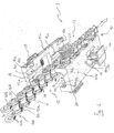
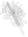
- the device 1 comprises a main body 10 made preferably of plastic material and having a substantially parallelepiped shape.
- the main body 10 is defined by an upper body 10a and a lower body 10b mutually connectable through suitable coupling means.
- the coupling means also carry out the precise centring of the upper body 10a with respect to the lower body 10b preferably through metallic pins (not illustrated) adapted to be housed in seats 110 formed in the upper body 10a and in the lower body 10b.
- the metallic pins are calibrated pins.
- the coupling means are defined by at least one couple of projecting elements formed on anyone of the upper body 10a and lower body 10b and adapted to be housed in respective seats formed on the other one of the upper body 10a and the lower body 10b.
- the main body 10 of device 1 extends along a longitudinal axis X which corresponds to the running direction of the chain 2 when the device 1 is mounted on the chain 2 to perform the cleaning action ( figure 4 ).
- the main body 10 has respectively a chain inlet opening 12 and a chain outlet opening 13.
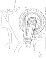
- device 1 is mounted on a straight branch 2a of the chain 2, preferably the lower branch, in the specific case of a motorbike 100 drive chain.
- Chain 2 cleaning action is carried out due to the running of chain 2 inside the main body 10 of the device 1 between the chain inlet opening 12 and the chain outlet opening 13. During such action the branch 2a of the chain 2 remains substantially straight.
- the relative movement between chain 2 and device 1 is obtained associating the main body 10 to any hold member 101 external to the device 1, for instance any part of the motorbike frame, and moving the chain 2 in suitable way, for instance pushing the motorbike along the road or, if the motorbike is placed on its central stand, pulling the chain or rotating the motorbike wheel.
- the coupling between main body 10 and hold member 101 is obtained preferably through a restraint cable 3, preferably made with a flexible material, associated at a first end thereof to a pin 14 projecting from a lower surface of the lower body 10b and, at the second end thereof, to the hold member 101 (see figure 4 ).
- cable 3 is associated to the pin 14 at a flare 14a defined on a head portion of pin 14 with reduced diameter, and is associated to the hold member 101 in a such a way that an angle ⁇ of reduced amplitude is defined between cable 3 and chain 2 (see figure 4 ).
- a restraint cable 3 preferably made with a flexible material
- angle ⁇ is comprised between 0° and ⁇ 90°, whilst it is preferably comprised between 0° and ⁇ 75°, more preferably between 0° and ⁇ 30°, when device 1 is working (i.e. when cable 3 is stretched by the chain movement).
- the pin 14 is provided on the lower surface of the lower body 10b in a substantially middle position. Therefore it is in an intermediate position between chain inlet opening 12 and chain outlet opening 13, i.e. in a neutral position with respect to the thrusts exerted at said openings during the running of the chain 2 inside the main body 10 of the device 1.
- the running of chain 2 inside the main body 10 of the device 1 is guided in the upper part and in the lower part by the contact between the internal links 50 and the external links 60 of the chain 2 and, respectively, the lower internal surface 11a of the main body 10 defined in the upper body 10a and the upper internal surface 11b of the main body 10 defined in the lower body 10b.
- the running of chain 2 inside the main body 10 of the device 1 is guided sideways, i.e. orthogonally to the longitudinal axis X of the device 1, by the contact between the internal links 50 and the external links 60 of the chain 2 and proper running guides 15, 16 defined in the main body 10.
- the main body 10 of the device 1 comprises a first running guide 15 defined centrally on the lower internal surface 11a of the upper body 10a; said guide 15 is provided with opposite side shoulders 15a and 15b adapted to act in abutment with the internal side surfaces of the opposite plates 50a, 50b of internal links 50 of the chain 2.
- Guide 15 extends on the upper body 10a along the longitudinal axis X for a first length at the chain inlet opening 12 and for a second length at the chain outlet opening 13.
- the longitudinal size of the first length of the guide 15 is at least equal to the pitch of the internal links 50 of the chain 2.
- the rounded shape of the internal links 50 facilitates the inlet of chain 2 in the main body 10 of the device 1.
- the main body 10 comprises a running guide 16 defined on the lower body 10b and adapted to act in abutment with the external links 60 of the chain 2.
- guide 16 is defined by a couple of opposite side shoulders 16a, 16b defined at the edge between the opposite internal side surfaces 11c of the lower body 10b and the internal upper surface 11b of the main body 10 defined in the lower body 10b.
- the shoulders 16a, 16b are adapted to act in abutment with the external side surfaces of the opposite plates 60a, 60b of the external links 60 of the chain 2.
- Guide 16 extends on the lower body 10b along the longitudinal axis X for a first length at the chain inlet opening 12 and for a second length at the chain outlet opening 13.
- the longitudinal size of the first length of the guide 16 is at least equal to the pitch of the external links 60 of the chain 2.
- the rounded shape of the external links 60 facilitates the inlet of the chain 2 in the main body 10 of the device 1.
- Guides 15 and 16 are sized in such a way not to come into contact with the ends of the pins 70 and with the rollers 71 of the chain 2.
- Dirt removal from chain 2 is carried out thanks to the mechanical action exerted on chain 2 by a plurality of brushes, all indicated with 20 in the attached drawings, properly positioned on the main body 10 of the device 1.
- Brushes 20 are mounted in proper seats formed on all the four sides walls of the main body 10 and are arranged in such a way to act from opposite sides both on the internal links 50 and on the external links 60 of the chain 2.
- the position of the brushes 20 on the main body 10 is such that opposite brushes are in different positions along the longitudinal axis X of the device 1.
- brushes 20 are removably connected to the main body 10, in order to permit their periodical replacement. Furthermore, the position of brushes 20 with respect to chain 2 may be adjustable, so that they can be moved close to chain 2 as bristles wear out. Furthermore, said brushes 20 may be pivotally mounted on the main body 10, i.e. in order to have a little balancing and/or rotating movement so to facilitate further the cleaning action of the chain 2.
- the surface profile of brushes 20 may be not straight. For instance, it is advantageous to provide a substantially S-shape profile.
- the opposite side surfaces of the main body 10 has respective lightening zones 30 with no material ( figure 3 ).
- the main body 10 comprises a reservoir 40 ( figure 2 ) acting as a tank for a cleaning and/or lubricating fluid.
- Reservoir 40 comprises one or several evacuation bores (not shown) with a diameter precisely sized to let fluid dropping by gravity. Said bore is inclined with respect to the longitudinal axis X by about 45°, and it opens into the main body 10 at the brushes 20 provided in the upper body 10a of the main body 10 of the device 1. In this way, brushes 20 are soaked with fluid, so that it is put on the chain 2. The movement of the bristles of brushes 20 due to the dragging caused by chain 2 uncovers the evacuation bore and permit the feeding of the fluid.
- the fact that the upper brushes 20 have a different position along the longitudinal axis X of the device 1 with respect to the lower brushes 20, causes the rotation of the chain rollers 71 and a better cleaning/lubricating action, facilitating the penetration of the fluid in the meatus existing between rollers 71 and pins 70.
Landscapes
- Engineering & Computer Science (AREA)
- Mechanical Engineering (AREA)
- General Engineering & Computer Science (AREA)
- Physics & Mathematics (AREA)
- Geometry (AREA)
- Arrangement Of Transmissions (AREA)
- Output Control And Ontrol Of Special Type Engine (AREA)
- Cleaning By Liquid Or Steam (AREA)
- Cleaning In General (AREA)
- Devices For Conveying Motion By Means Of Endless Flexible Members (AREA)
Applications Claiming Priority (1)
| Application Number | Priority Date | Filing Date | Title |
|---|---|---|---|
| IT001064A ITMI20071064A1 (it) | 2007-05-25 | 2007-05-25 | Dispositivo per la pulizia di una catena di trasmissione del moto |
Publications (2)
| Publication Number | Publication Date |
|---|---|
| EP1994854A2 true EP1994854A2 (fr) | 2008-11-26 |
| EP1994854A3 EP1994854A3 (fr) | 2009-11-18 |
Family
ID=39711933
Family Applications (1)
| Application Number | Title | Priority Date | Filing Date |
|---|---|---|---|
| EP08008558A Withdrawn EP1994854A3 (fr) | 2007-05-25 | 2008-05-07 | Dispositif de nettoyage pour circuit de transmission de mouvement |
Country Status (2)
| Country | Link |
|---|---|
| EP (1) | EP1994854A3 (fr) |
| IT (1) | ITMI20071064A1 (fr) |
Cited By (7)
| Publication number | Priority date | Publication date | Assignee | Title |
|---|---|---|---|---|
| ITMI20091942A1 (it) * | 2009-11-05 | 2011-05-06 | Silva Srl | Dispositivo per pulire la catena di una bicicletta. |
| CN103569066A (zh) * | 2013-11-21 | 2014-02-12 | 王瑾瑜 | 自行车链条清洗器 |
| JP2014133610A (ja) * | 2013-01-08 | 2014-07-24 | Nhk Spring Co Ltd | 潤滑油塗布装置 |
| WO2015174981A1 (fr) * | 2014-05-15 | 2015-11-19 | Applied Materials, Inc. | Dispositif d'élimination de particules et son procédé de fonctionnement |
| CN113351574A (zh) * | 2021-06-24 | 2021-09-07 | 苏州健雄职业技术学院 | 一种用于链条保养的自动化设备及其保养方法 |
| CN115890444A (zh) * | 2023-01-04 | 2023-04-04 | 江苏亚星锚链股份有限公司 | 一种用于锚链热处理后表面滚光处理设备 |
| WO2024026541A1 (fr) * | 2022-08-05 | 2024-02-08 | Andrew Greig | Outil de lubrification de chaîne |
Family Cites Families (7)
| Publication number | Priority date | Publication date | Assignee | Title |
|---|---|---|---|---|
| DE3669471D1 (de) * | 1985-03-06 | 1990-04-19 | Allsop Inc | Schmier- und reinigungsvorrichtung fuer fahrradkette. |
| NL8600171A (nl) * | 1986-01-27 | 1987-08-17 | Wubbo Johannes Ockels | Inrichting voor het reinigen van een op een rijwiel met derailleur gemonteerde fietsketting. |
| NL193062C (nl) * | 1990-02-13 | 2000-12-01 | Bernhard Leopold Roos | Kettingreiniger. |
| US5213180A (en) * | 1992-07-02 | 1993-05-25 | Masonek Steven J | Lubricant applicator for drive chain |
| DE19635728C1 (de) * | 1996-09-03 | 1998-01-15 | Max Wyssmann | Bürstenvorrichtung zum Schmieren und Reinigen von Führungs- und/oder Antriebselementen |
| AT406141B (de) * | 1997-03-07 | 2000-02-25 | Josef Pesl | Vorrichtung zum reinigen und schmieren von antriebsketten, insbesondere von motorrädern |
| ITBO20030483A1 (it) * | 2003-08-06 | 2005-02-07 | Barbieri S N C Di Barbieri Nadia E Kalman | Puliscicatena per bicicletta montato su bomboletta di soluzione detergente-lubrificante. |
-
2007
- 2007-05-25 IT IT001064A patent/ITMI20071064A1/it unknown
-
2008
- 2008-05-07 EP EP08008558A patent/EP1994854A3/fr not_active Withdrawn
Non-Patent Citations (1)
| Title |
|---|
| None |
Cited By (10)
| Publication number | Priority date | Publication date | Assignee | Title |
|---|---|---|---|---|
| ITMI20091942A1 (it) * | 2009-11-05 | 2011-05-06 | Silva Srl | Dispositivo per pulire la catena di una bicicletta. |
| EP2322415A1 (fr) * | 2009-11-05 | 2011-05-18 | SILVA S.r.l. | Appareil de nettoyage d'une chaîne de bicyclette |
| JP2014133610A (ja) * | 2013-01-08 | 2014-07-24 | Nhk Spring Co Ltd | 潤滑油塗布装置 |
| CN103569066A (zh) * | 2013-11-21 | 2014-02-12 | 王瑾瑜 | 自行车链条清洗器 |
| CN103569066B (zh) * | 2013-11-21 | 2015-06-17 | 王瑾瑜 | 自行车链条清洗器 |
| WO2015174981A1 (fr) * | 2014-05-15 | 2015-11-19 | Applied Materials, Inc. | Dispositif d'élimination de particules et son procédé de fonctionnement |
| CN113351574A (zh) * | 2021-06-24 | 2021-09-07 | 苏州健雄职业技术学院 | 一种用于链条保养的自动化设备及其保养方法 |
| WO2024026541A1 (fr) * | 2022-08-05 | 2024-02-08 | Andrew Greig | Outil de lubrification de chaîne |
| CN115890444A (zh) * | 2023-01-04 | 2023-04-04 | 江苏亚星锚链股份有限公司 | 一种用于锚链热处理后表面滚光处理设备 |
| CN115890444B (zh) * | 2023-01-04 | 2023-06-23 | 江苏亚星锚链股份有限公司 | 一种用于锚链热处理后表面滚光处理设备 |
Also Published As
| Publication number | Publication date |
|---|---|
| EP1994854A3 (fr) | 2009-11-18 |
| ITMI20071064A1 (it) | 2008-11-26 |
Similar Documents
| Publication | Publication Date | Title |
|---|---|---|
| EP1994854A2 (fr) | Dispositif de nettoyage pour circuit de transmission de mouvement | |
| JP5391266B2 (ja) | 溶融金属を入れる容器用のスライド蓋 | |
| US20100186564A1 (en) | Wire Saw | |
| JP5486955B2 (ja) | チェーンガイド装置 | |
| US10457524B2 (en) | Tension device for drive chain, method and escalator system using same | |
| FI108782B (fi) | Reunanhiomalaite rakenneosien reunojen pyöristämiseksi mekaanisesti | |
| US20100050589A1 (en) | Guide rail for cable protection and guide device | |
| CA2309362C (fr) | Scie a chaine | |
| JP4801753B2 (ja) | ベルトクリーナ装置 | |
| JP3359034B2 (ja) | 運搬手段、運搬手段の製造方法および運搬手段の構成 | |
| JP7299875B2 (ja) | 可撓性のランスを駆動する装置 | |
| RU2568528C2 (ru) | Способ и устройство для использования цепи | |
| KR101664802B1 (ko) | 세선 그리퍼를 이용한 전선포설장치 | |
| KR101375444B1 (ko) | 냉장고용 섀시의 표면연마장치 | |
| CA2216159A1 (fr) | Appareil de formation d'une demi-lune a neige | |
| KR101719804B1 (ko) | 컨베이어가 포함된 눈삽 제설장치 | |
| JP6326524B1 (ja) | ベルトクリーナ装置 | |
| US4494456A (en) | Conveyor belt apparatus | |
| EP4375393A1 (fr) | Dispositif de nettoyage de lèvre externe pour lame d'air | |
| RU2287685C2 (ru) | Направляющее устройство для цепи в горной машине | |
| CN212093861U (zh) | 一种钢管折弯设备 | |
| US7603884B1 (en) | Right angle track clip installation tool | |
| JP2016088715A (ja) | 給油ブラシ取付治具及び給油ブラシの取付方法 | |
| US7150142B2 (en) | Chicken chain | |
| CN2767761Y (zh) | 一种直线往复运动装置 |
Legal Events
| Date | Code | Title | Description |
|---|---|---|---|
| PUAI | Public reference made under article 153(3) epc to a published international application that has entered the european phase |
Free format text: ORIGINAL CODE: 0009012 |
|
| AK | Designated contracting states |
Kind code of ref document: A2 Designated state(s): AT BE BG CH CY CZ DE DK EE ES FI FR GB GR HR HU IE IS IT LI LT LU LV MC MT NL NO PL PT RO SE SI SK TR |
|
| AX | Request for extension of the european patent |
Extension state: AL BA MK RS |
|
| PUAL | Search report despatched |
Free format text: ORIGINAL CODE: 0009013 |
|
| AK | Designated contracting states |
Kind code of ref document: A3 Designated state(s): AT BE BG CH CY CZ DE DK EE ES FI FR GB GR HR HU IE IS IT LI LT LU LV MC MT NL NO PL PT RO SE SI SK TR |
|
| AX | Request for extension of the european patent |
Extension state: AL BA MK RS |
|
| AKX | Designation fees paid | ||
| REG | Reference to a national code |
Ref country code: DE Ref legal event code: 8566 |
|
| STAA | Information on the status of an ep patent application or granted ep patent |
Free format text: STATUS: THE APPLICATION IS DEEMED TO BE WITHDRAWN |
|
| 18D | Application deemed to be withdrawn |
Effective date: 20100519 |