EP1994858B1 - Fahrzeugsitz mit bildschirm - Google Patents
Fahrzeugsitz mit bildschirm Download PDFInfo
- Publication number
- EP1994858B1 EP1994858B1 EP07714610.8A EP07714610A EP1994858B1 EP 1994858 B1 EP1994858 B1 EP 1994858B1 EP 07714610 A EP07714610 A EP 07714610A EP 1994858 B1 EP1994858 B1 EP 1994858B1
- Authority
- EP
- European Patent Office
- Prior art keywords
- headrest
- monitor unit
- receiving portion
- head receiving
- seatback
- Prior art date
- Legal status (The legal status is an assumption and is not a legal conclusion. Google has not performed a legal analysis and makes no representation as to the accuracy of the status listed.)
- Not-in-force
Links
Images


Classifications
-
- B—PERFORMING OPERATIONS; TRANSPORTING
- B60—VEHICLES IN GENERAL
- B60R—VEHICLES, VEHICLE FITTINGS, OR VEHICLE PARTS, NOT OTHERWISE PROVIDED FOR
- B60R11/00—Arrangements for holding or mounting articles, not otherwise provided for
- B60R11/02—Arrangements for holding or mounting articles, not otherwise provided for for radio sets, television sets, telephones, or the like; Arrangement of controls thereof
- B60R11/0229—Arrangements for holding or mounting articles, not otherwise provided for for radio sets, television sets, telephones, or the like; Arrangement of controls thereof for displays, e.g. cathodic tubes
- B60R11/0235—Arrangements for holding or mounting articles, not otherwise provided for for radio sets, television sets, telephones, or the like; Arrangement of controls thereof for displays, e.g. cathodic tubes of flat type, e.g. LCD
-
- A—HUMAN NECESSITIES
- A47—FURNITURE; DOMESTIC ARTICLES OR APPLIANCES; COFFEE MILLS; SPICE MILLS; SUCTION CLEANERS IN GENERAL
- A47C—CHAIRS; SOFAS; BEDS
- A47C7/00—Parts, details, or accessories of chairs or stools
- A47C7/36—Supports for the head or the back
- A47C7/38—Supports for the head or the back for the head, e.g. detachable
-
- B—PERFORMING OPERATIONS; TRANSPORTING
- B60—VEHICLES IN GENERAL
- B60N—SEATS SPECIALLY ADAPTED FOR VEHICLES; VEHICLE PASSENGER ACCOMMODATION NOT OTHERWISE PROVIDED FOR
- B60N2/00—Seats specially adapted for vehicles; Arrangement or mounting of seats in vehicles
- B60N2/80—Head-rests
- B60N2/806—Head-rests movable or adjustable
- B60N2/809—Head-rests movable or adjustable vertically slidable
- B60N2/812—Head-rests movable or adjustable vertically slidable characterised by their locking devices
- B60N2/818—Head-rests movable or adjustable vertically slidable characterised by their locking devices with stepwise positioning
-
- B—PERFORMING OPERATIONS; TRANSPORTING
- B60—VEHICLES IN GENERAL
- B60N—SEATS SPECIALLY ADAPTED FOR VEHICLES; VEHICLE PASSENGER ACCOMMODATION NOT OTHERWISE PROVIDED FOR
- B60N2/00—Seats specially adapted for vehicles; Arrangement or mounting of seats in vehicles
- B60N2/80—Head-rests
- B60N2/806—Head-rests movable or adjustable
- B60N2/838—Tiltable
- B60N2/841—Tiltable characterised by their locking devices
- B60N2/85—Tiltable characterised by their locking devices with continuous positioning
-
- B—PERFORMING OPERATIONS; TRANSPORTING
- B60—VEHICLES IN GENERAL
- B60N—SEATS SPECIALLY ADAPTED FOR VEHICLES; VEHICLE PASSENGER ACCOMMODATION NOT OTHERWISE PROVIDED FOR
- B60N2/00—Seats specially adapted for vehicles; Arrangement or mounting of seats in vehicles
- B60N2/80—Head-rests
- B60N2/879—Head-rests with additional features not related to head-rest positioning, e.g. heating or cooling devices or loudspeakers
-
- B—PERFORMING OPERATIONS; TRANSPORTING
- B60—VEHICLES IN GENERAL
- B60R—VEHICLES, VEHICLE FITTINGS, OR VEHICLE PARTS, NOT OTHERWISE PROVIDED FOR
- B60R11/00—Arrangements for holding or mounting articles, not otherwise provided for
- B60R2011/0001—Arrangements for holding or mounting articles, not otherwise provided for characterised by position
- B60R2011/0003—Arrangements for holding or mounting articles, not otherwise provided for characterised by position inside the vehicle
- B60R2011/0012—Seats or parts thereof
- B60R2011/0017—Head-rests
-
- B—PERFORMING OPERATIONS; TRANSPORTING
- B60—VEHICLES IN GENERAL
- B60R—VEHICLES, VEHICLE FITTINGS, OR VEHICLE PARTS, NOT OTHERWISE PROVIDED FOR
- B60R11/00—Arrangements for holding or mounting articles, not otherwise provided for
- B60R2011/0042—Arrangements for holding or mounting articles, not otherwise provided for characterised by mounting means
- B60R2011/008—Adjustable or movable supports
- B60R2011/0082—Adjustable or movable supports collapsible, e.g. for storing after use
-
- B—PERFORMING OPERATIONS; TRANSPORTING
- B60—VEHICLES IN GENERAL
- B60R—VEHICLES, VEHICLE FITTINGS, OR VEHICLE PARTS, NOT OTHERWISE PROVIDED FOR
- B60R11/00—Arrangements for holding or mounting articles, not otherwise provided for
- B60R2011/0042—Arrangements for holding or mounting articles, not otherwise provided for characterised by mounting means
- B60R2011/008—Adjustable or movable supports
- B60R2011/0085—Adjustable or movable supports with adjustment by rotation in their operational position
Definitions
- the present invention relates to a vehicle seat with a monitor.
- US 6698832 B discloses a technique concerning an assembling structure for assembling a monitor unit to a seat.
- the monitor unit and a headrest are configured as separate units.
- the headrest has a shape in which its rear surface portion is gouged out, and the monitor unit is adapted to be slid from below so as to be fitted therein.
- the monitor unit in the monitor unit, through holes are formed in its pedestal portion for allowing stays, i.e., leg portions of the headrest, to be inserted therein at the time of fitting the monitor unit into the headrest. Accordingly, by fitting the stays into the monitor unit while inserting the stays into the through holes, the both members can be assembled into a compact form which imparts a sense of unity.
- the monitor unit can be configured to be separately independent so as not to follow the vertical movement of the headrest, i.e., the adjustment movement of the insertion length of the stays into the seatback. Therefore, since it is unnecessary to cause the wiring of the monitor unit to follow via the interior of the stay, it is possible to simplify the wiring in the interior of the seatback.
- US 2003/015631 A1 discloses a vehicle seat with a monitor in which a monitor unit is installed above a seat back and in the rear of a headrest.
- the headrest is mounted to the seat back by means of a pair of stays such that it can be withdrawn from the seat back and adjusted with respect to the height above the seat back.
- the monitor unit is rigidly attached to a supporting plate of the headrest and can be pivoted together with the supporting plate relative to the stays of the headrest.
- a cushion for receiving a back of a head of a vehicle occupant is separately pivotably supported on the supporting plate of the headrest by means of a hinge to be able to swing in a back-and-forth direction relative to the monitor unit in order to compensate the pivoting of the monitor unit.
- the configuration is such that the headrest is assembled to the monitor unit, and since a restriction is caused in its movable range, the headrest is has a simple configuration which permits only the adjustment movement in the vertical direction relative to the seatback.
- the present invention has been devised to overcome the above-described problem, and a problem to be solved by the invention is to ensure that the adjustment of the back-and-forth position of the headrest and the installed hight with respect to e seatback can be performed even in the configuration in which the monitor unit is assembled to the headrest.
- the vehicle seat with a monitor in accordance with the invention has the features of claim 1.
- the monitor unit has a hollow recess formed on the reverse side of the head receiving portion, and is disposed such that at least a portion of the monitor unit enters the recess, so that the monitor unit is assembled to the headrest into a compact form which imparts a sense of unity with the headrest.
- the head receiving portion of the headrest is adapted to be moved back and forth with respect to the stay by an actuating mechanism. In this back-and-forth movement of the head receiving portion, the head receiving portion moves to the close position where it is close to the monitor unit located on its rear side. Specifically, this close position is a state position in which a portion of the monitor unit has entered the interior of the recess formed on the reverse side of the head receiving portion.
- the arrangement provided is such that the relative approaching movement of the monitor unit is accepted by the recessed shape of the recess in the head receiving portion, and the headrest which moves back and forth and at least a portion of the monitor unit overlap.
- the back-and-forth width of the configuration combining the headrest and the monitor unit is reduced, a sense of unity is imparted, and the appearance can be improved.
- the back-and-forth movement of the head receiving portion is effected by the swinging motion about the hinge portion provided between the head receiving portion and the stay.
- the monitor unit even if the headrest undergoes swinging motion to be moved back and forth, since the curved portion of the monitor unit allows the movement of the headrest, a gap is not formed between the monitor unit and the headrest, so that it is possible to attain improvement of the appearance.
- an insertion and coupling structure between the stay of the headrest and the seatback has a structure in which, as the stay is inserted into an interior of an insertion port formed in an upper surface of the seatback, an adjustment groove formed in the stay is retained by a retaining pawl provided in the interior of the insertion port in such a manner as to be capable of projecting into and retracting from the interior of the insertion port, so as to restrict the movement of the stay in an inserting direction; wherein a plurality of adjustment grooves are formed in an inserting and drawing-out direction as the adjustment groove so as to allow adjustment of a position of an installed height of the headrest to be performed by the selection of the adjustment groove for being retained by the retaining pawl; and wherein a rear cover is mounted to a reverse surface portion of the head receiving portion so as to cover from a reverse surface side mounting structure portions of the head receiving portion and the stay which are exposed on an upper side of the monitor unit when the installed height of the headrest is raised.
- the mounting structure portions of the head receiving portion and the stay are covered from their reverse surface side by the rear cover.
- this rear cover covers the aforementioned mounting structure portions exposed on the upper side of the monitor unit.
- the rear cover is fixed to a side of the stay.
- the rear cover is not interlocked with the swinging motion of the headrest and is interlocked with only the vertical movement of the headrest.
- the rear cover allows the swinging of the headrest to be effected smoothly without interfering with the monitor unit.
- the rear cover covers the gap with the monitor unit when the headrest moves vertically, the appearance can be improved.
- a front cover for covering from a front surface side mounting structure portions of the monitor unit and the seatback is mounted to the monitor unit, and wherein the front cover assumes a state of covering the structure portions which are seen through a gap from a front side which is formed between the headrest and the seatback when the installed height of the headrest is raised.
- the mounting structure portions of the monitor unit and the seatback is covered from its front surface side by the front cover.
- this front cover covers the aforementioned structure portions exposed through the gap between the headrest and the seatback.
- the monitor unit is hinge-coupled to the seatback and has a display screen adapted to be made to undergo swinging motion in the back-and-forth direction about the hinge portion which hinge-coupled.
- the angle of inclination of the display screen can be varied.
- the monitor unit in a state in which the headrest is removed from the seatback, is adapted to be folded down by being reclined about the hinge portion toward the upper surface of the seatback.
- the center of the hinge for adjusting the angle of inclination of the display screen of the monitor unit serves as the center of the hinge at the time of reclining the monitor unit toward the upper surface of the seatback.
- side surface portions constituting surface portions on both left and right sides of the recess are respectively formed in the head receiving portion of the headrest, and the side surface portions are configured in a state of covering lateral gaps formed between the head receiving portion and the monitor unit at either moved position to which the head receiving portion has been moved back and forth.
- the lateral gaps formed between the head receiving portion and the monitor unit are covered by the side surface portions constituting the surface portions on both left and right sides of the recess in the head receiving portion. These side surface portions cover the lateral gaps formed between the head receiving portion and the monitor unit at the time when the head receiving portion is moved forwardly.
- the mechanism of adjusting the back-and-forth position of the headrest can be realized in a relatively simple configuration.
- a gap is not formed between the monitor unit and the headrest, thereby making it possible to improve the appearance.
- the mounting structure portions of the head receiving portion and the stay are covered by the rear cover, it is possible to ensure that the appearance of the reverse surface side of the headrest is not impaired.
- the swinging motion of the headrest can be effected smoothly, and when the headrest is vertically moved, the gap with the monitor unit is covered, thereby making it possible to improve the appearance.
- the mounting structure portions of the monitor unit and the seatback are covered by the front cover, it is possible to ensure that the appearance of the front surface side of the monitor unit which is seen through the gap between the headrest and the seatback is not impaired.
- the mechanism of adjusting the angle of inclination of the display screen of the monitor unit can be realized in a relatively simple configuration.
- themechanismof adjusting the angle of inclination of the display screen of the monitor unit can be used jointly with the mechanism of reclining the monitor unit toward the upper surface of the seatback.
- the lateral gaps formed between the head receiving portion and the monitor unit can be covered by the side surface portions of the head receiving portion, thereby making it possible to ensure that the appearance is not impaired.
- Fig. 1 is a perspective view illustrating a schematic structure of the vehicle seat with a monitor.
- Fig. 2 is a left side elevational view of Fig. 1 .
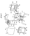
- Fig. 3 is an exploded perspective view of a mounting structure of a headrest 20 and a monitor unit 31.
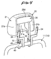
- Fig. 4 is a perspective view illustrating an installed state of the headrest 20.
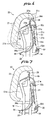
- Fig. 5 is a perspective view illustrating an installed state of the monitor unit 31.
- Fig. 6 is a side cross-sectional view corresponding to a cross section taken along line III-III in Fig.
- Fig. 7 is a side cross-sectional view corresponding to a cross section taken along line III-III in Fig. 5 , and illustrates a state in which the heightwise position of the headrest 20 has been raised.
- Fig. 8 is a cross-sectional view taken along line I-I in Fig. 1 .
- Fig. 9 is a cross-sectional view taken along line II-II in Fig. 2 .
- Fig. 10 is a perspective view illustrating a state in which the angle of inclination of the monitor unit 31 has been changed.
- FIG. 11 is a side elevational view for illustrating a state in which the monitor unit 31 is folded down by being reclined toward the upper surface of a seatback 10.
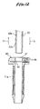
- Fig. 12 is a side cross-sectional view illustrating an inserting structure of a stay 22.
- Fig. 13 is a side cross-sectional view illustrating an inserted state of the stay 22.
- an "obverse surface” with respect to structural members such as the headrest 20 and the monitor unit 31 means a surface which faces the outer side in their assembled structure.
- a “reverse surface” means a surface on the opposite side to the “obverse surface.”
- a “front surface” means a surface which faces the front side with respect to the installed direction of a seat 1, whereas a “rear surface” means a surface on an opposite side thereto.
- the monitor unit 31 is installed on an upper surface portion of the seatback 10 constituting a backrest.
- This monitor unit 31 is disposed at the position of a reverse surface portion of the headrest 20 which is similarly installed on the upper surface portion of the seatback 10.
- the monitor unit 31 is disposed with its display screen 31a facing a seat (not shown) disposed on the rear side.
- Fig. 2 shows a left side surface of the headrest 20.
- Fig. 3 illustrates in an exploded perspective view a mounting structure of the headrest 20 and the monitor unit 31.
- Fig. 4 shows an installed state of the headrest 20 as a single unit.
- Fig. 5 shows an installed state of the monitor unit 31.
- the headrest 20 and the monitor unit 31 are mounted on a back frame 11 constituting the frame of the seatback 10.
- the headrest 20 has a head receiving portion 21, stays 22 and 23, a supporting device 24, a mounting fixture 25, and a rear cover 26.
- the head receiving portion 21 has a buffer structure in its front surface portion and is adapted to receive and support the back of an occupant's head.
- the head receiving portion 21 has a shape in which its reverse surface portion is gouged out, and this gauged-out portion is formed as a fitting recess 21a.
- side surface portions 21b for constituting surface portions on both left and right sides of the fitting recess 21a are respectively formed in the head receiving portion 21.
- the monitor unit 31 Since the side surface portions 21b are disposed so as to cover the side surfaces of the monitor unit 31, the monitor unit 31 is mounted in such a manner as to constantly overlap the headrest 20, thereby imparting a sense of unity and an attractive appearance.
- the stays 22 and 23 have their upper end portions coupled to the supporting device 24.
- the stays 22 and 23 and the supporting device 24 are, as a whole, assembled as component parts of a gate-shaped integrated type.
- the supporting device 24 is mounted on the reverse surface portion of the head receiving portion 21, these stays 22 and 23 are assembled in a state in which two rod-like members are suspended from the head receiving portion 21.
- the stays 22 and 23 thus assembled serve as leg portions for mounting the headrest 20.
- the stays 22 and 23 couple the headrest 20 to the seatback 10 as the stays 22 and 23 are respectively inserted into two supports 40 and 50 installed on the upper surface portion of the back frame 11, as shown in Fig. 4 .
- the headrest 20 can be held in a state of being installed on the upper surface portion of the seatback 10. It should be noted that a description will be given later of the coupling structure between the stays 22 and 23 and the supports 40 and 50.
- the aforementioned supporting device 24 is mounted to the head receiving portion 21 by means of the mounting fixture 25.
- This mounting fixture 25 is axially rotatably coupled to a hinge portion 24a of the supporting device 24.
- the mounting fixture 25 is integrally mounted to the reverse surface portion of the head receiving portion 21, as shown in Fig. 6 .
- the head receiving surface (front surface) of the head receiving portion 21 is made to undergo swinging motion about the hinge portion 24a in the back-and-forth direction relative to the stays 22 and 23.
- the head receiving portion 21 is adapted to accept the relative approaching movement of the monitor unit 31 by means of the recessed shape of the fitting recess 21a formed in its reverse surface portion.
- the swinging motion of the head receiving portion 21 can be effected between a close position indicated by the solid lines in the drawing and a spaced-apart position indicated by the imaginary lines.
- the close position indicated by the solid lines is a state position in which assembly structures, such as the monitor unit 31 and a front cover 36 assembled on its reverse surface 31b side, are entered into the interior of the shape of the head receiving portion 21 to allow the head receiving portion 21 to be brought close to the reverse surface 31b of the monitor unit 31.
- the swinging width of the back-and-forth movement of the head receiving portion 21 is absorbed within the shape of the head receiving portion 21.
- the spaced-apart position indicated by the imaginary lines is a state position in which the head receiving portion 21 has been forwardly moved to be spaced apart from the reverse surface 31b of the monitor unit 31 by being rotated about the hinge portion 24a in a counterclockwise direction shown in the drawing with respect to the above-described close position.
- a rear end portion 21c on the upper side of the head receiving portion 21 moves in a right downward direction shown in the drawing.
- the arrangement provided is such that the spaced apart movement of the head receiving portion 21 is allowed by a curved portion 36d formed in a front cover 36 where the rear end portion 21c is located on its lower side.
- the curved portion 36d of the front cover 36 allows the movement of the headrest 20, so that a gap is not produced between the monitor unit 31 and the headrest 20, thereby attaining the improvement of the appearance.
- the details of the front cover 36 will be described later.
- the above-described swinging motion of the head receiving portion 21 is constantly effected in a state in which the side surface portions 21b of the head receiving portion 21 face the side surfaces of the front cover 36 (see Fig. 1 ).
- the mounting structure portions of the stays 22 and 23 and the head receiving portion 21 are covered so as not to be seen through the gaps between the headrest 20 and the monitor unit 31.
- the rear cover 26 is mounted to the reverse surface portion of the head receiving portion 21 by means of the supporting device 24.
- This rear cover 26 is made of a synthetic resin and is disposed in such a manner as to cover the above-mentioned mounting structure portions of the stays 22 and 23 and the head receiving portion 21 from the reverse surface side.
- the rear cover 26 has a plate shape extending in a suspended direction from an upper portion of the reverse surface portion of the head receiving portion 21, and has a curved portion 26a for allowing the spaced apart movement of the head receiving portion 21 at its upper surface.
- the rear cover 26 covers the mounting structure portions of the stays 22 and 23 and the head receiving portion 21 from the rear surface side so that they will not be seen through a gap tb which is open on the upper side of the monitor unit 31. Also, when the headrest 20 undergoes swinging motion and moves back and forth, the curved portion 26a of the rear cover 26 allows the movement of the headrest 20, so that a gap is not produced between the monitor unit 31 and the headrest 20, thereby attaining the improvement of the appearance.
- the rear cover 26 since the rear cover 26 is fixed to the supporting device 24 on the stays 22 and 23 side, the rear cover 26 is not interlocked with the swinging motion of the headrest 20 and is interlocked with only the vertical movement of the headrest 20. As a result, even if the headrest 20 is swung, the rear cover 26 allows the swinging of the headrest 20 to be effected smoothly without interfering with the monitor unit 31, and since the rear cover 26 covers the gap with the monitor unit 31 when the headrest 20 moves vertically, the appearance improves.
- the stays 22 and 23 their lower end portions which are leading ends in the inserting direction are formed in a tapered manner.
- the tapered surfaces serve as guide surfaces, thereby facilitating the insertion of the stays 22 and 23.
- apluralityof adjustment grooves 22a and a retaining groove 22b are formed in one stay 22 on its side surface facing the other stay 23 along the longitudinal direction.
- the retaining groove 22b is formed on the lower side of the adjustment groove 22a formed at the lowest position.
- the respective supports 40 and 50 are respectively inserted and fixed in tubular fixing devices 11a fixed at two locations on the front side of the upper portion of the back frame 11.
- a retaining pawl 42 which is capable of retaining the stay 22 and preventing its movement is provided in the insertion port 41 of the support 40.
- This retaining pawl 42 is held by being constantly urged in a state in which it projects into the interior of the insertion port 41.
- an operation knob 43 is integrally provided on the retaining pawl 42. This operation knob 43 is capable of moving the retaining pawl 42 against the aforementioned urging force as a pushing operation in the leftward direction in the plane of the drawing is performed.
- the retaining pawl 42 can be temporarily withdrawn out of the port by its movement caused by this operation knob 43 (state of the imaginary lines).
- the retaining pawl 42 can be abutted against the outer peripheral surface of the stay 22 and can be set in a state of being pushed and retreated. It should be noted that the retaining pawl 42 may be configured such as to be directly pushed and retreated by the tapered surface of the stay 22 which is inserted.
- the heightwise positions of the retaining pawl 42 and the retaining groove 22b coincide in the course of time.
- the retaining pawl 42 is thrust into the retaining groove 22b by its resilient restoring force and retains it (see Fig. 13 ).
- the cross-sectional shapes of the retaining groove 22b and the retaining pawl 42 are illustrated in detail in Fig. 12 .
- the cross-sectional shape of the retaining groove 22b is formed in a U-shape in which its upper and lower surfaces forming its opening surfaces rise up straightly in the radial direction of the stay 22.
- the cross-sectional shape of the retaining pawl 42 is formed in a projecting shape which coincides with the U-shape of the retaining groove 22b. Accordingly, as shown in Fig. 13 , as the retaining groove 22b and the retaining pawl 42 having the aforementioned cross-sectional shapes are retained, the stay 22 is set in a state in which its movement in the inserting direction S and a drawing-out direction H is restrained.
- the operation knob 43 is subjected to the pushing operation in the above-described retained state, the state of retention between the retaining pawl 42 and the retaining groove 22b is released.
- the stay 22 can be further inserted into the interior of the insertion port 41.
- the heightwise positions of the retaining pawl 42 and the adjustment groove 22a coincide in the course of time.
- the retaining pawl 42 is thrust into the adjustment groove 22a by its resilient restoring force, and retains it (not shown).
- the cross-sectional shape of the adjustment groove 22a is illustrated in detail in Fig. 12 .
- the cross-sectional shape of the adjustment groove 22a is formed in a shape in which its upper surface forming its opening surface rises up straightly in the radial direction of the stay 22. Meanwhile, a lower surface forming its opening surface is formed as an inclined surface which gently rises up toward the outer peripheral surface of the stay 22. Accordingly, as the adjustment groove 22a and the retaining pawl 42 having the aforementioned cross-sectional shapes are retained, the stay 22 is set in a state in which its movement in the inserting direction S is restrained, but its movement in the drawing-out direction H is allowed.
- the retaining pawl 42 can be consecutively retained by each adjustment groove 22a. In this way, the adjustment of the position of the installed height of the headrest 20 can be performed by adjusting the amount of insertion of the stay 22. It should be noted that, in the state in which the retaining pawl 42 and the adjustment groove 22a are retained, if the headrest 20 as it is is operated so as to be lifted up in the drawing-out direction H, the stay 22 can be continued to be drawn out through the insertion port 41.
- the arrangement provided is such that, by virtue of this retaining structure, even if the headrest 20 is lifted up by chance in the drawing-out direction H, the installed state of the seatback 10 is maintained.
- the mounting structure of the monitor unit 31 is comprised of a monitor cover 32, a lower cover 33, supporting devices 34, and the front cover 36.
- the monitor cover 32 is made of a synthetic resin and is formed in a frame shape having a fitting opening 32a of a size allowing the monitor unit 31 to be fitted therein. As shown in Fig. 1 , this monitor cover 32 is assembled in a state in which the display screen 31a of the monitor unit 31 is exposed from the fitting opening 32a and its outer frame is covered thereby. In addition, returning to Fig. 3 , side surface portions 32b which are so shaped that they protrude forward so as to cover both side portions of the monitor unit 31 are formed in frame portions on both left and right sides of the monitor cover 32. An upper end surface and a lower end surface of this side surface portion 32b are formed in rounded curved shapes. Further, as shown in detail in Fig.
- the monitor unit 31 is assembled in such a manner as to be prevented from coming off.
- the guides 32c and 32d for preventing the monitor unit 31 from becoming positioning offset in the vertical direction are provided at an upper edge and a lower edge of the fitting port 32a of the monitor cover 32.
- the lower cover 33 is made of a synthetic resin and is formed in such as the shape of a pedestal for supporting the monitor cover 32 from below, as shown in Fig. 3 .
- This lower cover 33 is assembled to the lower side, and at its saucer-shaped sliding surface 33a formed on the upper surfaces of its left and right both side portions slidably supports the side surface portions 32b of the monitor cover 32 from below.
- a button hole 33b is formed at a lower position of the left side portion of the lower cover 33 (side portion at right on this side in the plane of the drawing).
- this button hole 33b is adapted to be located outside a release button 36c provided on the left side portion of this front cover 36.
- the arrangement provided is such that a finger can be inserted from outside through the button hole 33b with respect to the release button 36c.
- the supporting devices 34 are constituted by two frame members and are fixed by being welded to upper rear-side positions of the back frame 11.
- mounting fixtures 31c fixed to the reverse surface 31b of the monitor unit 31 are adapted to be respectively hinge-coupled to their upper end portions.
- a pin 31e is inserted in a hinge portion 34a formed in an end portion of the supporting device 34 and a pin hole 31d of the mounting fixture 31c, an end portion of the pin 31e is caulked to as to be fixed.
- the monitor unit 31 hinge-coupled to the supporting devices 34 is set in a state of being axially rotatable about the hinge portions 34a.
- the supporting device 34 is set in a shape in which it is bent toward the rear side of the vehicle in a chevron shape, as shown in Fig. 6 .
- the mounting fixture 31c is formed in a shape in which it is chamfered into a triangular shape with the hinge-coupled portion set as an apex.
- the front cover 36 is made of a synthetic resin and is adapted to be mounted on the reverse surface 31b (front surface) side of the monitor unit 31, as shown in Fig. 3 .
- this front cover 36 is assembled to the monitor cover 32 and the lower cover 33 by fitting in such a manner as to sandwich the monitor unit 31.
- the planar cover portion 36a for covering the aforementioned mounting structure portions of the supporting devices 34 and the monitor unit 31 from the front surface side is formed in the front cover 36.
- This cover portion 36a has a shape in which it rises upward from a lower portion of the front cover 36 in the shape of a curved surface, so as to fully cover the mounting structure portions mentioned above. As a result, as shown in Fig.
- the cover portion 36a covers the mounting structure portions of the supporting devices 34 and the monitor unit 31 from the front surface side so that they will not be seen through a gap tf which is open on the lower side of the headrest 20.
- the cross-sectional shape of this cover portion 36a is set in a shape in which it is bent toward the front side of the vehicle in a chevron shape. Specifically, the bending point of the chevron shape of the cover portion 36a is set at the height wise position of the hinge portions 34a which constitute the rotational center of the monitor unit 31. As a result, the cover portion 36a has an avoiding shape for accepting the axial rotation of the monitor unit 31.
- the front cover 36 having the above-described configuration is capable of restricting the rotation of the monitor unit 31 about the hinge portions 34a within a fixed range by being assembled to the monitor cover 32 and the lower cover 33. Namely, as shown in Fig. 10 , if the monitor unit 31 in the above-described assembled state is rotated either one direction, the reverse surface (front surface) of the monitor cover 32 which rotates integrally with the monitor unit 31 abuts (not shown) against the reverse surface (rear surface) of the front cover 36. As a result, the rotation of the monitor unit 31 is restrained.
- the monitor unit 31 in a state before the assembly of the front cover 36 thereto can be rotated freely about the hinge portions 34a. Accordingly, as indicated by the imaginary lines in the drawing, in the state in which the headrest 20 is removed from the seatback 10, the monitor unit 31 can be rotated and can be reclined toward the upper surface of the seatback 10 so as to be set in a folded-down attitude state. Accordingly, when, for example, the seat 1 is carried into the vehicle compartment, the seat 1 can be set in a compact form for facilitating the carrying of the seat 1 into the vehicle compartment by folding down the monitor unit 31 in advance in the above-described manner.
- vertically penetrating through holes 36b are formed at two left and right locations of the front cover 36 near its front side. These through holes 36b are adapted to allow the respective stays 22 and 23 of the headrest 20 to be inserted therein from the upper side when the headrest 20 is installed on the seatback 10. Accordingly, by inserting the stays 22 and 23 into these through holes 36b and then inserting them into the supports 40 and 50, the front cover 36 can be set like a pedestal and the headrest 20 can be installed on its upper side. Further, by installing the headrest 20 in this manner, the monitor unit 31 can be slid from below and fitted in the fitting recess 21a (for details see Fig. 4 ) formed in the reverse surface portion of the headrest 20.
- the headrest 20 and the monitor unit 31 can be assembled into a compact form which imparts a sense of unity.
- the monitor unit 31 can be configured to be separately independent so as not to follow the vertical movement of the headrest 20. Therefore, it is unnecessary to cause the wiring of the monitor unit 31 to follow the movement via, for instance, the interior of the stay 22 or the stay 23, and it is possible to simplify the wiring in the interior of the seatback 10.
- the release button 36c is formed on the above-described front cover 36 at a lower position of its left side portion (side portion at right on this side in the plane of the drawing).
- this release button 36c is disposed at a position outside the operation knob 43 of the support 40.
- the overall assembly structures of the monitor unit 31 are illustrated in a state in which they are lifted higher than the original position of the installed height. Accordingly, in actuality, the assembly structures of the monitor unit 31 are located on a lower side than in the illustrated state in Fig. 5 , and the release button 36c is disposed at a position immediately outside the operation knob 43.
- the aforementioned release button 36c is adapted to allow the pushing operation of the operation knob 43 to be effected by its pushing operation. Namely, the pushing operation of the operation knob 43 can be performed from the position on the left outer side of the front cover 36.
- the monitor unit 31 is hinge-coupled to the seatback 10 by means of the supporting devices 34, as shown in Fig. 11 .
- the monitor cover 32 and the lower cover 33 are mounted to the monitor unit 31, and the front cover 36 is in a pre-mounting state.
- the headrest 20 is set in a state of being removed from the seatback 10. Accordingly, in this state, the monitor unit 31 can be reclined about the hinge portions 34a toward the upper surface of the seatback 10 so as to be set in a folded-down attitude state, as indicated by the imaginary lines in Fig. 11 .
- the seat 1 can be carried into the vehicle compartment after being set in a compact attitude state.
- the monitor unit 31 is returned to its state of the upright attitude.
- the front cover 36 is assembled by being fitted from the reverse surface 31b side (front surface side) of the monitor unit 31.
- the monitor unit 31 can be rotated only in a fixed range, as shown in Fig. 10 .
- the display screen 31a see Fig. 1
- the monitor unit 31 facing the rear seat not shown
- the stays 22 and 23 assembled to the headrest 20 are inserted into the supports 40 and 50 of the back frame 11.
- the stays 22 and 23 are inserted into the respective supports 40 and 50.
- the headrest 20 and the monitor unit 31 are assembled into a compact form which imparts a sense of unity.
- the head receiving surface constituting the front surface of the head receiving portion 21 of the headrest 20 can be made to undergo swinging motion about the hinge portions 24a in the back-and-forth direction.
- the head receiving portion 21 can be moved between the close position indicated by the solid lines in the drawing and the spaced-apart position indicated by the imaginary lines, thereby making it possible to perform the adjustment of the back-and-forth position with respect to the seatback 10.
- the headrest 20 when the headrest 20 is removed from the seatback 10, it suffices if the headrest 20 is pulled upward while the pushing operation of the release button 36c disposed on its left position is being performed. As a result, the headrest 20 can be removed simply from the seatback 10.
- the swinging width in the back-and-forth movement of the head receiving portion 21 can be absorbed by the depth of the fitting recess 21a of the head receiving portion 21, so that it is possible to reduce the back-and-forth width in the configuration in which the headrest 20 and the monitor unit 31 are combined. Accordingly, even in the configuration in which the monitor unit 31 is assembled to the headrest 20, the adjustment of the back-and-forth position of the headrest 20 with respect to the seatback 10 can be performed in a compact form.
- the mounting structure portions of the head receiving portion 21 and the stays 22 and 23 are covered by the rear cover 26, it is possible to ensure that the appearance of the reverse surface side of the headrest 20 is not impaired, and the swinging motion of the headrest 20 can be effected smoothly. Furthermore, since the mounting structure portions of the monitor unit 31 and the seatback 10 are covered by the front cover 36, it is possible to ensure that the appearance of the front surface side of the monitor unit 31 which is seen through the gap tf between the headrest 20 and the seatback 10 is not impaired, and the swinging motion of the headrest 20 can be effected smoothly.
- hinge portions 34a it is possible to provide a simple structure in which the mechanism of adjusting the angle of inclination of the display screen 31a of the monitor unit 31 and the mechanism of reclining the monitor unit 31 toward the upper surface of the seatback 10 are combined.
- the side surface portions 21b of the head receiving portion 21 it is possible to cover lateral gaps formed between the head receiving portion 21 and the monitor unit 31 and ensure that the appearance will not be impaired.
- Fig. 14 is an exploded perspective view of a mounting structure of the headrest 20 and a monitor unit 131 of the vehicle seat with a monitor.
- the monitor unit 131 is adapted to be rigidly fixed to a supporting device 134 fixed to the back frame 11 of the seatback 10.
- a mounting base plate 137 is rigidly fixed to the supporting device 134, and the monitor unit 131 is adapted to be mounted thereto.
- the monitor unit 131 is configured so as not to rotate in the manner shown in embodiment 1.
- a monitor cover 132 is so shaped that although the configuration in which the monitor cover 132 is integrally assembled to the outer frame of the monitor unit 131 so as to cover it is the same, the monitor cover 132 is integrally assembled to a front cover 136 as well. It should be noted that the configuration of a release button 136c provided on the front cover 136 is substantially the same as that of the release button 36c shown in embodiment 1.
- the monitor unit 131 can also be configured to be rigidly fixed to the back frame 11. In addition, if a comparison is made with the configuration described in embodiment 1, this makes it possible to simplify the respective cover structures mounted to the monitor unit 131.
- the hinge portion for reclining the monitor unit toward the upper surface of the seatback and the hinge portion for adjusting the angle of inclination of the display screen may be set in different portions.
- the release button may not necessarily be formed on the front cover, and may be formed on another component member such as a monitor cover.
- a hole allowing a finger to reach the operation knob may only be formed without setting the release button.
- the cover portion of the front cover shown in embodiment 1 may not be structured to fully cover the mounting structure portions of the monitor unit. Namely, the cover portion is sufficient is it is capable of covering over the mounting structure portions of the monitor unit so that they will not be seen through the gap which is open on the lower side of the headrest. Accordingly, the cover portion may also be configured by being formed into such a shape (such as the shape of the cover portion 136 shown in Fig. 11 ) that only a lower region portion of the configuration shown in embodiment 1 is left and an upper region portion thereof is removed, so as to perform the covering function only by this lower region portion. By so doing, it becomes possible to accept the swinging motion of the monitor unit by the portion of the removed upper region portion, thereby making it possible to reduce the back-and-forth width of the configuration combining the headrest and the monitor unit.
Landscapes
- Engineering & Computer Science (AREA)
- Mechanical Engineering (AREA)
- Aviation & Aerospace Engineering (AREA)
- Transportation (AREA)
- Chair Legs, Seat Parts, And Backrests (AREA)
- Fittings On The Vehicle Exterior For Carrying Loads, And Devices For Holding Or Mounting Articles (AREA)
Claims (7)
- Ein Fahrzeugsitz (1) mit einem Monitor, in dem eine Monitoreinheit (31) über einer Sitzrückenlehne (10) und in der Rückseite einer Kopfstütze (20) installiert ist, wobei:die Kopfstütze (20) einen Kopfaufnahmeabschnitt (21) zum Aufnehmen einer Rückseite eines Kopfes eines Fahrzeuginsassen, eine hohle Ausnehmung (21a), welche an einer rückwärtigen Seite des Kopfaufnahmeabschnitts (21) ausgebildet ist, aufweist und die Kopfstütze (20) so angeordnet ist, dass mindestens ein Abschnitt der Monitoreinheit (31) in die Ausnehmung (21a) eintritt,wobei die Kopfstütze (20) und die Monitoreinheit (31) unabhängig und separat an einem oberen Oberflächenabschnitt der Sitzrückenlehne (10) gelagert und angeordnet sind,wobei die Kopfstütze (20) mit einer Strebe (22,23) zum abziehbaren Befestigen der Kopfstütze (20) an der Sitzrückenlehne (10) versehen ist,wobei ein Betätigungsmechanismus, der eine Bewegung des Kopfaufnahmeabschnitts (21) vor und zurück relativ bezüglich der Sitzrückenlehne (10) erlaubt, an einem Verbindungsabschnitt zwischen der Strebe (22,23) der Kopfstütze (20) und dem Kopfaufnahmeabschnitt (21) vorgesehen ist, wobei der Betätigungsmechanismus ein Gelenkabschnitt (24a) zum gelenkigen Koppeln des Kopfaufnahmeabschnitts (21) und der Strebe (22,23) ist, derart, dass der Kopfaufnahmeabschnitt (21) eingerichtet ist, eine Schwenkbewegung um den Gelenkabschnitt (24a) in einer Richtung vor und zurück und relativ zu der Monitoreinheit (31) zwischen einer Schließposition, in welcher der Kopfaufnahmeabschnitt (21) nahe einem rückwärtigen Abschnitt der Monitoreinheit (31) ist, und einer beabstandeten Position, in welcher der Kopfaufnahmeabschnitt (21) nach vorne bewegt worden ist, um von der Schließposition beabstandet zu sein, auszuführen, undwobei der Kopfaufnahmeabschnitt (21) eingerichtet ist, um die relative Annäherungsbewegung der Monitoreinheit (31) mittels einer Ausnehmungsform der Ausnehmung (21a) aufzunehmen, ein gekrümmter Abschnitt (36d) mit einer gekrümmten Form zum Zulassen der Schwenkbewegung des Kopfaufnahmeabschnitts (21) in einem oberen Abschnitt der Monitoreinheit (31) vorgesehen ist, und mindestens ein Abschnitt der Monitoreinheit (31) in der Ausnehmung (21a) unabhängig von der Bewegung der Kopfstütze (20) aufgenommen ist.
- Der Fahrzeugsitz (1) mit einem Monitor gemäß Anspruch 1, wobei eine Einsetz- und Kopplungsstruktur zwischen der Strebe (22,23) der Kopfstütze (20) und der Sitzrückenlehne (10) eine Struktur besitzt, in der, während die Strebe (22,23) in ein Inneres eines Einsetzanschlusses (41,51), welcher in einer oberen Fläche der Sitzrückenlehne (10) ausgebildet ist, eingesetzt wird, eine Einstellnut (22a), welche in der Strebe (22,23) ausgebildet ist, durch eine Halteklaue gehalten ist, welche in dem Inneren des Einsetzanschlusses (41,51) auf solche Weise vorgesehen ist, dass sie in das Innere des Einsetzanschlusses (41,51) vorstehen und davon zurückgezogen werden kann, um die Bewegung der Strebe (22,23) in einer Einsetzrichtung zu begrenzen,
wobei eine Vielzahl von Einstellnuten (22a) in einer Einsetz- und Ausziehrichtung als die Einstellnut (22a) ausgebildet sind, um eine Einstellung einer Position einer installierten Höhe der Kopfstütze (20) zuzulassen, die ausgewählt wird, indem die Einstellnut (22a), welche durch die Halteklaue zu halten ist, und
wobei eine hintere Abdeckung (26) an einem rückwärtigen Oberflächenabschnitt des Kopfaufnahmeabschnitts (21) so angebracht ist, dass sie von einer rückwärtigen Oberflächenseite Befestigungsstrukturabschnitte des Kopfaufnahmeabschnitts (21) und der Strebe (22,23) abdecket, welche an einer oberen Seite der Monitoreinheit (31) freiliegen, wenn die Einbauhöhe der Kopfstütze (20) angehoben ist. - Der Fahrzeugsitz (1) mit einem Monitor gemäß Anspruch 2, wobei die hintere Abdeckung (26) an einer Seite der Strebe (22,23) befestigt ist.
- Der Fahrzeugsitz (1) mit einem Monitor gemäß Anspruch 2 oder 3, wobei eine vordere Abdeckung (36) zum Abdecken von Befestigungsstrukturabschnitten der Monitoreinheit (31) und der Sitzrückenlehne (10) von einer vorderen Seite an der Monitoreinheit (31) angebracht ist, und
wobei die vordere Abdeckung (36) einen Zustand des Abdeckens der Strukturabschnitte, welche durch einen zwischen der Kopfstütze (20) und der Sitzrückenlehne (10) beim Anheben der Installationshöhe der Kopfstütze (20) ausgebildeten Zwischenraum (tf) von einer Vorderseite sichtbar sind, einnimmt. - Der Fahrzeugsitz (1) mit einem Monitor gemäß einem der Ansprüche 1 bis 4, wobei die Monitoreinheit (31) gelenkig mit der Sitzrückenlehne (10) gekoppelt ist und einen Anzeigebildschirm (31a) besitzt, der eingerichtet ist, um eine Schwenkbewegung in der Richtung vor und zurück um einen Gelenkabschnitt (34a) auszuführen.
- Der Fahrzeugsitz (1) mit einem Monitor gemäß Anspruch 5, wobei in einem Zustand, bei dem die Kopfstütze (20) von der Sitzrückenlehne (10) entfernt ist, die Monitoreinheit (31) eingerichtet ist, um durch zurückneigen um den Gelenkabschnitt (34a) zu der oberen Oberfläche der Sitzrückenlehne (10) nach unten gefaltet zu werden.
- Der Fahrzeugsitz (1) mit einem Monitor gemäß einem der Ansprüche 1 bis 6, wobei Seitenflächenabschnitte (21b), welche Oberflächenabschnitte an beiden linken und rechten Seiten der Ausnehmung (21a) bilden, jeweils in dem Kopfaufnahmeabschnitt (21) der Kopfstütze (20) ausgebildet sind, und die Seitenflächenabschnitte (21b) in einem Zustand konfiguriert sind, bei dem sie laterale Zwischenräume abdecken, welche zwischen dem Kopfaufnahmeabschnitt (21) und der Monitoreinheit (31) an jeder Bewegungsposition gebildet sind, in welche der Kopfaufnahmeabschnitt (21) vor- und zurück bewegt worden ist.
Applications Claiming Priority (2)
| Application Number | Priority Date | Filing Date | Title |
|---|---|---|---|
| JP2006072397 | 2006-03-16 | ||
| PCT/JP2007/053110 WO2007108271A1 (ja) | 2006-03-16 | 2007-02-20 | モニター付き車両用シート |
Publications (4)
| Publication Number | Publication Date |
|---|---|
| EP1994858A1 EP1994858A1 (de) | 2008-11-26 |
| EP1994858A4 EP1994858A4 (de) | 2012-12-12 |
| EP1994858B1 true EP1994858B1 (de) | 2014-04-16 |
| EP1994858B8 EP1994858B8 (de) | 2014-07-09 |
Family
ID=38522307
Family Applications (1)
| Application Number | Title | Priority Date | Filing Date |
|---|---|---|---|
| EP07714610.8A Not-in-force EP1994858B8 (de) | 2006-03-16 | 2007-02-20 | Fahrzeugsitz mit bildschirm |
Country Status (5)
| Country | Link |
|---|---|
| US (1) | US7637565B2 (de) |
| EP (1) | EP1994858B8 (de) |
| JP (1) | JP4894760B2 (de) |
| CN (1) | CN100581418C (de) |
| WO (1) | WO2007108271A1 (de) |
Cited By (1)
| Publication number | Priority date | Publication date | Assignee | Title |
|---|---|---|---|---|
| EP2963741A1 (de) | 2014-07-02 | 2016-01-06 | Robert Virant | Rücksitz-Infotainmentsystem und mehradrige elektrische Verbinder für ein solches System |
Families Citing this family (21)
| Publication number | Priority date | Publication date | Assignee | Title |
|---|---|---|---|---|
| US8780282B2 (en) * | 2003-11-07 | 2014-07-15 | Voxx International Corporation | Vehicle entertainment system |
| US20050235327A1 (en) * | 2003-11-07 | 2005-10-20 | Vitito Christopher J | Vehicle entertainment system |
| US8954844B2 (en) * | 2004-01-13 | 2015-02-10 | Nuance Communications, Inc. | Differential dynamic content delivery with text display in dependence upon sound level |
| WO2008086202A2 (en) | 2007-01-05 | 2008-07-17 | Audiovox Corporation | Rear seat entertainment system for a vehicle having an active headrest |
| US7758116B2 (en) * | 2007-02-23 | 2010-07-20 | Toyota Boshoku Kabushiki Kaisha | Monitor unit for a vehicle seat |
| TWI392602B (zh) * | 2010-07-06 | 2013-04-11 | Sysgration Ltd | Headrest media player |
| US8556342B2 (en) | 2010-12-23 | 2013-10-15 | Nissan North America, Inc. | Headrest wire harness routing guide assembly |
| US8820832B2 (en) | 2011-11-22 | 2014-09-02 | Nissan North America, Inc. | Active head restraint with wiring pass-through |
| KR101154841B1 (ko) | 2012-02-17 | 2012-06-18 | (주)큐디스 | 차량용 모니터 고정장치 |
| US9555726B2 (en) * | 2012-08-23 | 2017-01-31 | Zodiac Seats Us Llc | Seatback energy management system |
| DE102013010067A1 (de) * | 2013-06-11 | 2014-12-11 | Sertan Gürbüz | Gerät für die Wiedergabe elektronischer Medien |
| JP5653499B1 (ja) | 2013-10-04 | 2015-01-14 | 日本発條株式会社 | ヘッドレスト、車両用シート |
| US9510685B2 (en) * | 2014-05-02 | 2016-12-06 | Steelcase Inc. | Office system telepresence arrangement |
| CN104168496A (zh) * | 2014-07-29 | 2014-11-26 | 常熟恒基科技有限公司 | 一种车载新型液晶显示器 |
| US9421892B1 (en) * | 2015-01-29 | 2016-08-23 | Toyota Motor Engineering & Manufacturing North America, Inc. | Headrest with retainer |
| US9487157B1 (en) * | 2015-07-10 | 2016-11-08 | Ford Global Technologies, Llc | Vehicle display assembly including an energy absorption element |
| USD835929S1 (en) * | 2016-03-03 | 2018-12-18 | Samsung Display Co., Ltd. | Automotive headrest |
| US10384578B2 (en) * | 2017-07-21 | 2019-08-20 | Ford Global Technologies, Llc | Seat assembly visor |
| CN112124210A (zh) * | 2020-08-28 | 2020-12-25 | 恒大新能源汽车投资控股集团有限公司 | 车辆座椅和机动车辆 |
| JP7754703B2 (ja) * | 2021-12-16 | 2025-10-15 | トヨタ自動車株式会社 | 情報処理装置、及び、情報処理方法 |
| CN117360345B (zh) * | 2023-12-07 | 2024-03-26 | 浙江嘉丰汽车座椅有限公司 | 一种汽车座椅的支撑头枕结构 |
Family Cites Families (9)
| Publication number | Priority date | Publication date | Assignee | Title |
|---|---|---|---|---|
| EP1260407B1 (de) * | 2001-05-25 | 2012-01-11 | Johnson Controls GmbH | Fahrzeugsitz mit integriertem Bildschirmgerät |
| TW507704U (en) * | 2001-07-20 | 2002-10-21 | Fa-You Ju | Regulating structure for headrest for mounting television |
| US6669285B1 (en) * | 2002-07-02 | 2003-12-30 | Eric Park | Headrest mounted video display |
| US7070237B2 (en) * | 2002-08-13 | 2006-07-04 | Epsilon Electronics, Inc. | Universal vehicle headrest monitor supporting bracket assembly |
| US7044546B2 (en) * | 2002-08-14 | 2006-05-16 | Johnson Safety, Inc. | Headrest-mounted monitor |
| JP2004081385A (ja) | 2002-08-26 | 2004-03-18 | Onkyo Corp | モニタ装置付きヘッドレスト |
| US6739654B1 (en) * | 2003-04-24 | 2004-05-25 | Hexa-Chain Co., Ltd. | Headrest-mount display mounting structure |
| US20050099042A1 (en) * | 2003-11-07 | 2005-05-12 | Vitito Christopher J. | Installation apparatus for an automobile entertainment system |
| US7758116B2 (en) * | 2007-02-23 | 2010-07-20 | Toyota Boshoku Kabushiki Kaisha | Monitor unit for a vehicle seat |
-
2007
- 2007-02-20 WO PCT/JP2007/053110 patent/WO2007108271A1/ja not_active Ceased
- 2007-02-20 US US11/909,834 patent/US7637565B2/en not_active Expired - Fee Related
- 2007-02-20 CN CN200780000416A patent/CN100581418C/zh not_active Expired - Fee Related
- 2007-02-20 EP EP07714610.8A patent/EP1994858B8/de not_active Not-in-force
- 2007-02-20 JP JP2007540850A patent/JP4894760B2/ja not_active Expired - Fee Related
Cited By (1)
| Publication number | Priority date | Publication date | Assignee | Title |
|---|---|---|---|---|
| EP2963741A1 (de) | 2014-07-02 | 2016-01-06 | Robert Virant | Rücksitz-Infotainmentsystem und mehradrige elektrische Verbinder für ein solches System |
Also Published As
| Publication number | Publication date |
|---|---|
| EP1994858B8 (de) | 2014-07-09 |
| JP4894760B2 (ja) | 2012-03-14 |
| US7637565B2 (en) | 2009-12-29 |
| EP1994858A1 (de) | 2008-11-26 |
| EP1994858A4 (de) | 2012-12-12 |
| WO2007108271A1 (ja) | 2007-09-27 |
| US20090261638A1 (en) | 2009-10-22 |
| CN100581418C (zh) | 2010-01-20 |
| JPWO2007108271A1 (ja) | 2009-08-06 |
| CN101321481A (zh) | 2008-12-10 |
Similar Documents
| Publication | Publication Date | Title |
|---|---|---|
| EP1994858B1 (de) | Fahrzeugsitz mit bildschirm | |
| JP3735935B2 (ja) | ヘッドレスト装置 | |
| US7871129B2 (en) | Seat assembly having an adjustable head restraint assembly | |
| RU147472U1 (ru) | Кресло для транспортного средства с шарнирным узлом подголовника | |
| CA2759128C (en) | Single slot lift and rotate mechanism | |
| US8668239B2 (en) | Storage compartment device | |
| US20150130248A1 (en) | Powered head restraint electrical connector | |
| US10906444B2 (en) | Multi-function connectivity module | |
| WO2023024477A1 (zh) | 座椅电动头枕和车辆座椅 | |
| JP2024523736A (ja) | 調節可能なカーシート・キャノピー | |
| US8814270B2 (en) | Folding headrest closeout member | |
| KR20070101929A (ko) | 차량의 리프트블 시트 | |
| JP4254374B2 (ja) | 車両シートのサイドサポート装置 | |
| JP5375504B2 (ja) | 車両用シート | |
| KR101372108B1 (ko) | 시트 높이 조절 연동형 슬라이딩 레버장치 | |
| JP2020199872A (ja) | チャイルドシート及びチャイルドシート用の固定ユニット | |
| KR100774419B1 (ko) | 폴딩 시트용 헤드레스트 높이 제어장치 | |
| JP3649974B2 (ja) | リクライニングシートの格納式アームレスト構造 | |
| JP3234085B2 (ja) | ビルトイン式チャイルドシートのロック機構 | |
| KR100786009B1 (ko) | 차량 시트백의 리클라이닝 및 폴딩 동작 겸용장치 | |
| US12030408B2 (en) | Device for unlocking seat of vehicle | |
| CN111006281B (zh) | 一种装饰罩安装装置及应用有该安装装置的吸油烟机 | |
| CN210852164U (zh) | 车载小桌板结构及车辆 | |
| JP2002264708A (ja) | 車両用シート構造 | |
| JP2005289329A (ja) | サンルーフ装置 |
Legal Events
| Date | Code | Title | Description |
|---|---|---|---|
| PUAI | Public reference made under article 153(3) epc to a published international application that has entered the european phase |
Free format text: ORIGINAL CODE: 0009012 |
|
| 17P | Request for examination filed |
Effective date: 20070831 |
|
| AK | Designated contracting states |
Kind code of ref document: A1 Designated state(s): DE FR GB |
|
| RIN1 | Information on inventor provided before grant (corrected) |
Inventor name: HATTORI, TSUNETOSHIC/O TOYOTA BOSHOKU KABUSHIKA KA Inventor name: KUNO, SATOROC/O TOYOTA BOSHOKU KABUSHIKA KAISHA Inventor name: HARADA, YUICHIC/O TOYOTA BOSHOKU KABUSHIKA KAISHA |
|
| DAX | Request for extension of the european patent (deleted) | ||
| RBV | Designated contracting states (corrected) |
Designated state(s): DE FR GB |
|
| A4 | Supplementary search report drawn up and despatched |
Effective date: 20121112 |
|
| RIC1 | Information provided on ipc code assigned before grant |
Ipc: B60R 11/02 20060101ALI20121106BHEP Ipc: A47C 7/38 20060101AFI20121106BHEP Ipc: A47C 7/72 20060101ALI20121106BHEP Ipc: B60N 2/48 20060101ALI20121106BHEP |
|
| GRAP | Despatch of communication of intention to grant a patent |
Free format text: ORIGINAL CODE: EPIDOSNIGR1 |
|
| INTG | Intention to grant announced |
Effective date: 20130913 |
|
| GRAS | Grant fee paid |
Free format text: ORIGINAL CODE: EPIDOSNIGR3 |
|
| GRAA | (expected) grant |
Free format text: ORIGINAL CODE: 0009210 |
|
| AK | Designated contracting states |
Kind code of ref document: B1 Designated state(s): DE FR GB |
|
| REG | Reference to a national code |
Ref country code: GB Ref legal event code: FG4D |
|
| REG | Reference to a national code |
Ref country code: DE Ref legal event code: R096 Ref document number: 602007036109 Country of ref document: DE Effective date: 20140528 |
|
| RIN2 | Information on inventor provided after grant (corrected) |
Inventor name: KUNO, SATORU C/O TOYOTA BOSHOKU KABUSHIKI KAISHA Inventor name: HATTORI, TSUNETOSHI C/O TOYOTA BOSHOKU KABUSHIKA K Inventor name: HARADA, YUICHI C/O TOYOTA BOSHOKU KABUSHIKA KAISHA |
|
| REG | Reference to a national code |
Ref country code: DE Ref legal event code: R097 Ref document number: 602007036109 Country of ref document: DE |
|
| PLBE | No opposition filed within time limit |
Free format text: ORIGINAL CODE: 0009261 |
|
| STAA | Information on the status of an ep patent application or granted ep patent |
Free format text: STATUS: NO OPPOSITION FILED WITHIN TIME LIMIT |
|
| 26N | No opposition filed |
Effective date: 20150119 |
|
| REG | Reference to a national code |
Ref country code: DE Ref legal event code: R097 Ref document number: 602007036109 Country of ref document: DE Effective date: 20150119 |
|
| REG | Reference to a national code |
Ref country code: DE Ref legal event code: R119 Ref document number: 602007036109 Country of ref document: DE |
|
| GBPC | Gb: european patent ceased through non-payment of renewal fee |
Effective date: 20150220 |
|
| REG | Reference to a national code |
Ref country code: FR Ref legal event code: ST Effective date: 20151030 |
|
| PG25 | Lapsed in a contracting state [announced via postgrant information from national office to epo] |
Ref country code: GB Free format text: LAPSE BECAUSE OF NON-PAYMENT OF DUE FEES Effective date: 20150220 Ref country code: DE Free format text: LAPSE BECAUSE OF NON-PAYMENT OF DUE FEES Effective date: 20150901 |
|
| PG25 | Lapsed in a contracting state [announced via postgrant information from national office to epo] |
Ref country code: FR Free format text: LAPSE BECAUSE OF NON-PAYMENT OF DUE FEES Effective date: 20150302 |