EP1994859A1 - Ressort de pression composé d'un faisceau de matière synthétique renforcé en fibres, en particulier utilisé dans un matelas élastique alvéolé et procédé de fabrication - Google Patents
Ressort de pression composé d'un faisceau de matière synthétique renforcé en fibres, en particulier utilisé dans un matelas élastique alvéolé et procédé de fabrication Download PDFInfo
- Publication number
- EP1994859A1 EP1994859A1 EP08008808A EP08008808A EP1994859A1 EP 1994859 A1 EP1994859 A1 EP 1994859A1 EP 08008808 A EP08008808 A EP 08008808A EP 08008808 A EP08008808 A EP 08008808A EP 1994859 A1 EP1994859 A1 EP 1994859A1
- Authority
- EP
- European Patent Office
- Prior art keywords
- fiber
- compression spring
- winding turns
- plastic strand
- reinforced plastic
- Prior art date
- Legal status (The legal status is an assumption and is not a legal conclusion. Google has not performed a legal analysis and makes no representation as to the accuracy of the status listed.)
- Withdrawn
Links
Images

Classifications
-
- A—HUMAN NECESSITIES
- A47—FURNITURE; DOMESTIC ARTICLES OR APPLIANCES; COFFEE MILLS; SPICE MILLS; SUCTION CLEANERS IN GENERAL
- A47C—CHAIRS; SOFAS; BEDS
- A47C27/00—Spring, stuffed or fluid mattresses or cushions specially adapted for chairs, beds or sofas
- A47C27/04—Spring, stuffed or fluid mattresses or cushions specially adapted for chairs, beds or sofas with spring inlays
- A47C27/06—Spring inlays or spring units therefor
- A47C27/063—Spring inlays or spring units therefor wrapped or otherwise protected
- A47C27/064—Pocketed springs
-
- A—HUMAN NECESSITIES
- A47—FURNITURE; DOMESTIC ARTICLES OR APPLIANCES; COFFEE MILLS; SPICE MILLS; SUCTION CLEANERS IN GENERAL
- A47C—CHAIRS; SOFAS; BEDS
- A47C27/00—Spring, stuffed or fluid mattresses or cushions specially adapted for chairs, beds or sofas
- A47C27/04—Spring, stuffed or fluid mattresses or cushions specially adapted for chairs, beds or sofas with spring inlays
- A47C27/06—Spring inlays or spring units therefor
- A47C27/065—Spring inlays or spring units therefor of special shape
-
- B—PERFORMING OPERATIONS; TRANSPORTING
- B29—WORKING OF PLASTICS; WORKING OF SUBSTANCES IN A PLASTIC STATE IN GENERAL
- B29C—SHAPING OR JOINING OF PLASTICS; SHAPING OF MATERIAL IN A PLASTIC STATE, NOT OTHERWISE PROVIDED FOR; AFTER-TREATMENT OF THE SHAPED PRODUCTS, e.g. REPAIRING
- B29C70/00—Shaping composites, i.e. plastics material comprising reinforcements, fillers or preformed parts, e.g. inserts
- B29C70/04—Shaping composites, i.e. plastics material comprising reinforcements, fillers or preformed parts, e.g. inserts comprising reinforcements only, e.g. self-reinforcing plastics
- B29C70/06—Fibrous reinforcements only
- B29C70/10—Fibrous reinforcements only characterised by the structure of fibrous reinforcements, e.g. hollow fibres
- B29C70/16—Fibrous reinforcements only characterised by the structure of fibrous reinforcements, e.g. hollow fibres using fibres of substantial or continuous length
- B29C70/20—Fibrous reinforcements only characterised by the structure of fibrous reinforcements, e.g. hollow fibres using fibres of substantial or continuous length oriented in a single direction, e.g. roofing or other parallel fibres
-
- B—PERFORMING OPERATIONS; TRANSPORTING
- B29—WORKING OF PLASTICS; WORKING OF SUBSTANCES IN A PLASTIC STATE IN GENERAL
- B29C—SHAPING OR JOINING OF PLASTICS; SHAPING OF MATERIAL IN A PLASTIC STATE, NOT OTHERWISE PROVIDED FOR; AFTER-TREATMENT OF THE SHAPED PRODUCTS, e.g. REPAIRING
- B29C70/00—Shaping composites, i.e. plastics material comprising reinforcements, fillers or preformed parts, e.g. inserts
- B29C70/04—Shaping composites, i.e. plastics material comprising reinforcements, fillers or preformed parts, e.g. inserts comprising reinforcements only, e.g. self-reinforcing plastics
- B29C70/28—Shaping operations therefor
- B29C70/30—Shaping by lay-up, i.e. applying fibres, tape or broadsheet on a mould, former or core; Shaping by spray-up, i.e. spraying of fibres on a mould, former or core
- B29C70/32—Shaping by lay-up, i.e. applying fibres, tape or broadsheet on a mould, former or core; Shaping by spray-up, i.e. spraying of fibres on a mould, former or core on a rotating mould, former or core
-
- B—PERFORMING OPERATIONS; TRANSPORTING
- B29—WORKING OF PLASTICS; WORKING OF SUBSTANCES IN A PLASTIC STATE IN GENERAL
- B29C—SHAPING OR JOINING OF PLASTICS; SHAPING OF MATERIAL IN A PLASTIC STATE, NOT OTHERWISE PROVIDED FOR; AFTER-TREATMENT OF THE SHAPED PRODUCTS, e.g. REPAIRING
- B29C70/00—Shaping composites, i.e. plastics material comprising reinforcements, fillers or preformed parts, e.g. inserts
- B29C70/68—Shaping composites, i.e. plastics material comprising reinforcements, fillers or preformed parts, e.g. inserts by incorporating or moulding on preformed parts, e.g. inserts or layers, e.g. foam blocks
- B29C70/84—Shaping composites, i.e. plastics material comprising reinforcements, fillers or preformed parts, e.g. inserts by incorporating or moulding on preformed parts, e.g. inserts or layers, e.g. foam blocks by moulding material on preformed parts to be joined
- B29C70/845—Shaping composites, i.e. plastics material comprising reinforcements, fillers or preformed parts, e.g. inserts by incorporating or moulding on preformed parts, e.g. inserts or layers, e.g. foam blocks by moulding material on preformed parts to be joined by moulding material on a relative small portion of the preformed parts
-
- F—MECHANICAL ENGINEERING; LIGHTING; HEATING; WEAPONS; BLASTING
- F16—ENGINEERING ELEMENTS AND UNITS; GENERAL MEASURES FOR PRODUCING AND MAINTAINING EFFECTIVE FUNCTIONING OF MACHINES OR INSTALLATIONS; THERMAL INSULATION IN GENERAL
- F16F—SPRINGS; SHOCK-ABSORBERS; MEANS FOR DAMPING VIBRATION
- F16F1/00—Springs
- F16F1/36—Springs made of rubber or other material having high internal friction, e.g. thermoplastic elastomers
- F16F1/366—Springs made of rubber or other material having high internal friction, e.g. thermoplastic elastomers made of fibre-reinforced plastics, i.e. characterised by their special construction from such materials
-
- B—PERFORMING OPERATIONS; TRANSPORTING
- B29—WORKING OF PLASTICS; WORKING OF SUBSTANCES IN A PLASTIC STATE IN GENERAL
- B29L—INDEXING SCHEME ASSOCIATED WITH SUBCLASS B29C, RELATING TO PARTICULAR ARTICLES
- B29L2031/00—Other particular articles
- B29L2031/774—Springs
-
- B—PERFORMING OPERATIONS; TRANSPORTING
- B29—WORKING OF PLASTICS; WORKING OF SUBSTANCES IN A PLASTIC STATE IN GENERAL
- B29L—INDEXING SCHEME ASSOCIATED WITH SUBCLASS B29C, RELATING TO PARTICULAR ARTICLES
- B29L2031/00—Other particular articles
- B29L2031/774—Springs
- B29L2031/7742—Springs helical springs
Definitions
- Compression spring of a fiber-reinforced plastic strand in particular for use in a pocket spring mattress, with manufacturing method
- the invention relates to a compression spring, which has a fiber-reinforced plastic strand and is particularly suitable as an insert in a pocket spring mattress.
- the invention also relates to methods for producing such a compression spring.
- a mattress core made of foam. This has transverse to its longitudinal axis extending cavities, are arranged lying in the coil springs of a strip material.
- the coil springs are made of a strip material and a fiber composite material and foamed.
- the structural element comprises a band-shaped body made of a plastic with stiffening fibers in a spiral arrangement.
- Such spiral-shaped bodies can be designed in the form of one or more nested winding tubes or in the form of a spirally slotted tube. It is intended to arrange a multiplicity of such spiral bodies next to one another and to provide them with cover layers.
- large, pillow-like padded elements can be formed with different geometries.
- the invention is based on the object to provide a compression spring and method for their preparation, which can be used in particular in a pocket spring mattress as a replacement for conventional metallic compression springs.
- the compression spring according to the invention whose winding gears consist of an endless conditioned fiber-reinforced plastic strand, which is homogeneously interconnected in the crossing points of the winding turns, represents a particularly advantageous, compact self-contained component. Due to the homogeneous connection of the endless plastic strand in the crossing points forms the The lateral surface of the compression spring quasi a network of coupled spring elements with closed nodes. This structure can be fatigue-free loaded with compressive forces, and is thus excellent as a replacement of metal springs, e.g. inside of pocket spring mattresses suitable.
- the compression spring according to the invention is particularly robust when the winding turns have a central axis and the crossing points are offset approximately diametrically, so are approximately radially relative to this axis.
- This embodiment is characterized by an approximately uniform distribution of homogeneously connected, closed nodes of the plastic strand on the lateral surface of the compression spring.
- the winding passages of the conditioned, fiber-reinforced plastic strand describe an approximately cylindrical lateral surface.
- the winding turns can also be shaped differently in cross section, e.g. square, honeycomb or oval.
- the compression spring of the invention formed by an endless hybrid yarn which has been conditioned by means of heat and / or pressure.
- a hybrid yarn is known to be an initially bendable strand of a loose abundance of endless technical fibers and synthetic fibers.
- the technical fibers e.g. Glass, polyaramid, carbon fibers, the tensile strength of the fiber mixture ready.
- the engineering fibers are then bonded by conditioning the admixed plastic fibers to the fiber reinforced plastic strand. This has after completion of the conditioning on a significant flexural rigidity, so that the winding turns of the formed therefrom spring under load can develop a good spring action.
- the plastic fibers melt.
- the strand can combine in the intersection points of the superimposed winding turns particularly homogeneous. After cooling and curing, the strand and its points of intersection have a solid matrix structure in which the technical fibers are embedded. These knots are particularly resilient. If the fiber-reinforced plastic strand is additionally compressed during the molten phase, at least in the crossing points of the winding turns, then the connection can be made be further improved.
- the conditioning of the endless hybrid yarn and thus the homogeneous connection of the fiber-reinforced plastic strand in the crossing points of the winding passes after the formation of the winding turns can also be effected by a combined heat and pressure treatment.
- the fiber-reinforced plastic strand of the compression spring according to the invention is formed by an endless, preconditioned plastic strand, which has been conditioned again by means of heat and / or pressure.
- the starting material used here is a fiber-reinforced plastic strand which is already in conditioned form. This can be made by preconditioning a hybrid yarn of the type described above in a conventional manner. The resulting, rigid and often rod-shaped stretched plastic strand is now subjected to the preparation of compression spring according to the invention of a new conditioning. The thereby taking place again molten heating of the strand then makes the formation of the winding turns of the compression spring and above all a homogeneous connection of the superimposed in the crossing points winding passes possible.
- the processing steps correspond to the above-described processing of flexible hybrid yarn as the starting material. Again, the compound in the crossing points by an additional compression during the molten phase can be further improved.
- the fiber-reinforced plastic strand of the compression spring according to the invention by an endless, impregnated fiber strand be formed, which has been conditioned by means of heat and / or pressure.
- the starting material used herein is a flexible strand of a loose mass of continuous engineering fibers which is filled with a liquid resin, e.g. with a thermoset, are soaked.
- a liquid resin e.g. with a thermoset
- the conditioning of the starting material and thus the formation of the homogeneous compounds in the crossing points of the winding passes can be advantageously carried out by a combined heat and pressure treatment. As a result, a curing of the liquid resin is effected.
- the fiber-reinforced plastic strand of the compression spring according to the invention can be formed by an endless fiber strand, which has been conditioned with liquid plastic.
- This starting material is a flexible strand of a loose abundance of endless technical fibers.
- This is conditioned before, during or after the formation of the winding turns by applying or introducing liquid plastic.
- Such a material is also referred to as ROVING, which is preferably conditioned for example by spraying liquid plastic after the formation of the winding turns or by impregnating with liquid plastic during or after the formation of the winding turns and a subsequent curing phase. Since this curing takes place without heat and pressure, additional compression of the fiber-reinforced plastic strand after the formation of the winding turns at least in the crossing points The winding gears also benefit here.
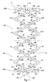
- Fig. 1 shows in a lateral plan view of an endless, fiber-reinforced plastic strand 2, which is wound according to the invention to form a compression spring 1.
- a compression spring 1 For better understanding while the winding turns of the endless, fiber-reinforced plastic strand are resolved by arrows in individual spring arcs. The directions of the arrows also indicate the associated winding directions.
- the point 2A of the plastic strand 2 at the lower end of the foot represents the beginning of the entire coil.
- the first, leading winding passage has the spring arcs a2-a5 in the region of the first gradient S1, the spring arcs a6-a9 in the region of the second gradient, and merges at the head end into an outgoing spring bow a10.
- the endless plastic strand 2 now goes from the two spring bows b0, b1, which complete the support ring AR2, in a second, returning winding over. This is directed downward and extends over the two slopes S2, S1 again to the lower end of the compression spring.
- the second, rewinding winding passage has the spring arcs b2-b5 in the region of the second pitch S2, the spring arcs b6-b9 in the area of the first pitch, and merges into an outgoing spring bow b10 at the foot end.
- the endless fiber-reinforced plastic strand 2 is now continued in the lower support ring AR1 in the two spring cords c0, c1, which form a Currentthewindung.
- This goes into a third, leading winding over, which is compared to the first, leading winding turn on the central axis A rotated by 180 degrees. This is also directed upward and extends over the two slopes S1, S2 to the upper head of the compression spring.
- This third, leading winding course has the spring arcs c2-c5 in the region of the first gradient S1, the spring arcs c6-c9 in the region of the second gradient, and merges at the head end into an outgoing spring arc c10. This in turn represents a part of the upper support ring AR2.
- the endless fiber-reinforced plastic strand 2 continues into the spring arcs d0, d1, which form a final initial half-turn in the upper support ring AR2.
- These spring arcs d0, d1 merge into a last, fourth, returning winding turn, which is also rotated by 180 degrees relative to the second, returning winding pass on the central axis A.
- This fourth winding passage is also directed downward and extends over the two slopes S2, S1 again to the lower end of the compression spring.
- the fourth, rewinding winding passage has the spring arcs d2-d5 in the region of the second gradient S2, the spring arcs d6-d9 in the region of the first pitch, and merges at the foot end into the outgoing spring arcs d10, d11.
- At the end 2E of the spring bow d11 also ends of the fiber-reinforced plastic strand 2 and thus the compression spring 2 performing endless winding.
- Fig. 1 shows a lateral plan view of the compression spring, lying in the rear winding area spring arches are covered by lying in the front winding area spring bows.
- This is symbolized by the fact that the front visible, visible bows with continuous arrows, and behind lying, covered Federbögen are marked with dashed arrows.
- the spring when acting on the compression spring from the top of the upper support ring AR2 in the direction of the central axis A compressive force, the spring by corresponding bending the between the nodes k1 - k18 lying spring arcs a2 - a9, b2 - b9, c2 - c9 and d2 - d9 compressed.
- the inventive, homogeneous compound of the conditioned plastic strand in the nodes causes extremely robust, insensitive to strong pressure forces structure of the compression spring according to the invention.
- the leading and returning winding turns of the plastic strand 2 of the compression spring is an at least two-start coil spring with at least two clockwise and two left-pitched slopes.
- the crossing points of the wicking length are offset approximately diametrically relative to the axis of the compression spring, or are even distributed approximately radially on quadrants.
- Such embodiments are in the example of Fig. 1 already shown.
- the node pairs k3, k4 or k7, k8 or k11, k12 or k15, k16 lie on the lateral surface of the pressure spring 1
- the node pairs k1, k2 or k5, k6 or k9 are offset by 90 degrees thereto.
- k10 or k13, k14 or k17, k18 with respect to the axis A are diametrically opposite each other.
- the nodes k3, k7, k11, k15, or the nodes k1, k5, k9, k13, k17, or the nodes k4, k8, k12, k16, or the nodes k2, k6, k10, k14, k18 each lie in a quadrant.
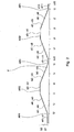
- Fig. 2 is the winding structure of the fiber-reinforced plastic strand 2 belonging to the construction of the compression spring 1 shown.
- the individual revolutions of the winding are marked on the x axis extending to the right, and the two gradients S1, S2 on the upward ⁇ axis.
- the individual areas of the winding are the corresponding spring curves a2-a5, a6-a9, b2-b5, b6-b9, c2-c5, c6-c9, d2-d5 and d6-d9 assigned.
- those spring arcs a0-a1, c0-c1 which belong to the lower support ring AR1 and those spring arcs b0-b1, d0-d1 which belong to the upper support ring AR2 are also recorded.
- Fig. 3 is the exemplary compression spring 1 of Fig. 1 shown again. Furthermore, the nodes K1 to k18 located at points of intersection are also recorded. In addition, the spring elements F1 to F17 delimited by the individual nodes and the adjacent spring arcs of the winding passages are marked.
- the particular advantage of the compression spring 1 according to the invention is seen in the fact that its lateral surface is quasi a network of the spring elements F1 - F17, which are coupled to each other via the nodes K1 - K18 represents.
- the spring element F8 is formed by the nodes k6, k7, k8, k10 and the between spring arches. The nodes k6, k7, k8, k10 simultaneously form the couplings to the adjacent spring elements F4, F5, F6, F9, F10, F12 and F7.
- Fig. 4 Finally, also shows the compression spring 1, wherein the view from the Fig. 3 rotated 90 degrees to the right on the A axis.
Landscapes
- Engineering & Computer Science (AREA)
- Mechanical Engineering (AREA)
- Chemical & Material Sciences (AREA)
- Composite Materials (AREA)
- General Engineering & Computer Science (AREA)
- Textile Engineering (AREA)
- Springs (AREA)
Applications Claiming Priority (2)
| Application Number | Priority Date | Filing Date | Title |
|---|---|---|---|
| DE102007023577A DE102007023577A1 (de) | 2007-05-21 | 2007-05-21 | Druckfeder aus einem faserverstärkten Kunststoffstrang, insbesondere zur Verwendung in einer Taschenfederkernmatratze, mit Herstellungsverfahren |
| DE202007007236U DE202007007236U1 (de) | 2007-05-21 | 2007-05-21 | Druckfeder aus einem faserverstärkten Kunststoffstrang, insbesondere zur Verwendung in einer Taschenfederkernmatratze |
Publications (1)
| Publication Number | Publication Date |
|---|---|
| EP1994859A1 true EP1994859A1 (fr) | 2008-11-26 |
Family
ID=43877243
Family Applications (1)
| Application Number | Title | Priority Date | Filing Date |
|---|---|---|---|
| EP08008808A Withdrawn EP1994859A1 (fr) | 2007-05-21 | 2008-05-12 | Ressort de pression composé d'un faisceau de matière synthétique renforcé en fibres, en particulier utilisé dans un matelas élastique alvéolé et procédé de fabrication |
Country Status (2)
| Country | Link |
|---|---|
| EP (1) | EP1994859A1 (fr) |
| DE (2) | DE202007007236U1 (fr) |
Cited By (2)
| Publication number | Priority date | Publication date | Assignee | Title |
|---|---|---|---|---|
| EP3167768A1 (fr) * | 2015-11-16 | 2017-05-17 | Siegbert Hartmann | Carcasse de matelas à ressorts ensachés |
| CN112797097A (zh) * | 2021-01-14 | 2021-05-14 | 李嘉欣 | 一种弹簧及乳液泵 |
Families Citing this family (3)
| Publication number | Priority date | Publication date | Assignee | Title |
|---|---|---|---|---|
| DE202009004803U1 (de) * | 2009-05-12 | 2010-07-15 | Froli Kunststoffwerk Heinrich Fromme Ohg | Federkernelement für den Einsatz in eine Matratze, beispielsweise Taschenfederkernmatratze |
| DE102010043703A1 (de) | 2010-11-10 | 2012-05-10 | Arwed Theuer | Teller- oder Wellfeder |
| CN110589079B (zh) * | 2019-08-20 | 2021-04-23 | 广州市联柔机械设备有限公司 | 袋装弹簧柔性封装装置、方法、制造设备及袋装弹簧 |
Citations (4)
| Publication number | Priority date | Publication date | Assignee | Title |
|---|---|---|---|---|
| GB427118A (en) * | 1933-10-19 | 1935-04-16 | Douglas Rowland Drummond | Improvements relating to coil springs, particularly for upholstery |
| US20020158392A1 (en) * | 2001-04-30 | 2002-10-31 | Cornell Research Foundation, Inc. | Multihelical composite spring |
| DE10228406A1 (de) | 2001-06-25 | 2003-01-02 | Bernhard Scheuring | Spiralförmiges Strukturelement sowie Verbundbauteil bestehend aus wenigstens einem spiralförmigen Strukturelement und einem Außenbauteil |
| EP1285607A1 (fr) | 2001-08-14 | 2003-02-26 | Franz Ing. Kutschi | Matelas ave un noyau en mousse |
-
2007
- 2007-05-21 DE DE202007007236U patent/DE202007007236U1/de not_active Expired - Lifetime
- 2007-05-21 DE DE102007023577A patent/DE102007023577A1/de not_active Withdrawn
-
2008
- 2008-05-12 EP EP08008808A patent/EP1994859A1/fr not_active Withdrawn
Patent Citations (4)
| Publication number | Priority date | Publication date | Assignee | Title |
|---|---|---|---|---|
| GB427118A (en) * | 1933-10-19 | 1935-04-16 | Douglas Rowland Drummond | Improvements relating to coil springs, particularly for upholstery |
| US20020158392A1 (en) * | 2001-04-30 | 2002-10-31 | Cornell Research Foundation, Inc. | Multihelical composite spring |
| DE10228406A1 (de) | 2001-06-25 | 2003-01-02 | Bernhard Scheuring | Spiralförmiges Strukturelement sowie Verbundbauteil bestehend aus wenigstens einem spiralförmigen Strukturelement und einem Außenbauteil |
| EP1285607A1 (fr) | 2001-08-14 | 2003-02-26 | Franz Ing. Kutschi | Matelas ave un noyau en mousse |
Cited By (2)
| Publication number | Priority date | Publication date | Assignee | Title |
|---|---|---|---|---|
| EP3167768A1 (fr) * | 2015-11-16 | 2017-05-17 | Siegbert Hartmann | Carcasse de matelas à ressorts ensachés |
| CN112797097A (zh) * | 2021-01-14 | 2021-05-14 | 李嘉欣 | 一种弹簧及乳液泵 |
Also Published As
| Publication number | Publication date |
|---|---|
| DE202007007236U1 (de) | 2008-07-17 |
| DE102007023577A1 (de) | 2008-12-04 |
Similar Documents
| Publication | Publication Date | Title |
|---|---|---|
| EP2511084B1 (fr) | Elément de noeud en matière plastique renforcée de fibres et procédé de fabrication et d'utilisation associé | |
| EP3218170B1 (fr) | Élément structural en matériau renforcé par des fibres et son procédé de fabrication | |
| EP1902167A2 (fr) | Materiau composite en forme de barre renforce par des fibres, procede et dispositif pour sa production | |
| DE2757965A1 (de) | Schubuebertragungselement und verfahren zu dessen herstellung | |
| EP1994859A1 (fr) | Ressort de pression composé d'un faisceau de matière synthétique renforcé en fibres, en particulier utilisé dans un matelas élastique alvéolé et procédé de fabrication | |
| DE102013219820A1 (de) | Faserverbundwerkstoffbauteil, Verfahren zur Herstellung eines Faserverbundwerkstoffbauteils sowie Verwendung von Faserbündeln und Verstrebungsmitteln zur Herstellung eines Faserverbundwerkstoffbauteils | |
| WO2019105629A1 (fr) | Corps composite à base de fibres et procédé servant à fabriquer un corps composite à base de fibres | |
| DE2520623A1 (de) | Rohr aus faserverstaerkten kunststoffen | |
| DE102015102440B4 (de) | Verfahren zur Herstellung eines Faserverbund-Hohlkörpers mit helixförmiger Kontur | |
| DE3145153A1 (de) | Stranggezogner verankerungsstab aus aushaertbarem kunstharz | |
| EP0690228B1 (fr) | Manchette de montage et poutre de flexion pour pale aérodynamique | |
| EP3057779A1 (fr) | Procédé de production d'un élément structural composite renforcé par des fibres | |
| DE102007040609B4 (de) | Verfahren zur Herstellung eines seilartigen Federelementhalbzeugs, eines spiralförmigen Federelements, ein Werkzeug zur Bearbeitung eines seilartigen Federelementhalbzeugs, Vorrichtung zur Herstellung eines spiralförmigen Federelements | |
| EP3490782B1 (fr) | Procédé pour la fabrication d'une pièce composite à fibres multicouche, tridimensionnelle | |
| DE2230324A1 (de) | Rohrfoermiger schichtstoff und verfahren zu seiner herstellung | |
| EP3162546A1 (fr) | Élément de traction en matière plastique renforcée de fibres | |
| DE102018117472B4 (de) | Faserverbundbauteil für den Einsatz im Kraftfahrzeugbereich sowie Verfahren zur Herstellung eines derartigen Faserverbundbauteils | |
| WO2016193451A1 (fr) | Rampe distributrice de carburant | |
| DE102014220134B4 (de) | Verfahren zur Herstellung von Faserverbund-Hohlprofilen | |
| EP0174295A2 (fr) | Procédé de fabrication de tuyaux | |
| DE102012206384A1 (de) | Faser-Flechtprofil | |
| DE102019104427A1 (de) | Rohrförmiges Faserhalbzeug, faserverstärktes Kunststoffhohlprofil, Verfahren zur Herstellung eines Faserhalbzeugs und Verfahren zur Herstellung eines faserverstärkten Kunststoffhohlprofils | |
| DE102021200228B4 (de) | Scheibe aus Kunststoff, Verfahren zur Herstellung der Scheibe und Computerprogrammprodukt | |
| DE1083372B (de) | Verfahren zur Herstellung eines stabfoermigen Zugisolators | |
| DE1704459C (de) | Verfahren zur Herstellung eines Ver bundbauteils aus glasfaserverstärktem Kunststoff |
Legal Events
| Date | Code | Title | Description |
|---|---|---|---|
| PUAI | Public reference made under article 153(3) epc to a published international application that has entered the european phase |
Free format text: ORIGINAL CODE: 0009012 |
|
| AK | Designated contracting states |
Kind code of ref document: A1 Designated state(s): AT BE BG CH CY CZ DE DK EE ES FI FR GB GR HR HU IE IS IT LI LT LU LV MC MT NL NO PL PT RO SE SI SK TR |
|
| AX | Request for extension of the european patent |
Extension state: AL BA MK RS |
|
| AKX | Designation fees paid |
Designated state(s): AT BE BG CH CY CZ DE DK EE ES FI FR GB GR HR HU IE IS IT LI LT LU LV MC MT NL NO PL PT RO SE SI SK TR |
|
| STAA | Information on the status of an ep patent application or granted ep patent |
Free format text: STATUS: THE APPLICATION IS DEEMED TO BE WITHDRAWN |
|
| 18D | Application deemed to be withdrawn |
Effective date: 20090527 |