EP1994873B1 - Abbildungseinrichtung - Google Patents
Abbildungseinrichtung Download PDFInfo
- Publication number
- EP1994873B1 EP1994873B1 EP07714197.6A EP07714197A EP1994873B1 EP 1994873 B1 EP1994873 B1 EP 1994873B1 EP 07714197 A EP07714197 A EP 07714197A EP 1994873 B1 EP1994873 B1 EP 1994873B1
- Authority
- EP
- European Patent Office
- Prior art keywords
- ion conducting
- aperture
- image pickup
- lens
- conducting actuator
- Prior art date
- Legal status (The legal status is an assumption and is not a legal conclusion. Google has not performed a legal analysis and makes no representation as to the accuracy of the status listed.)
- Not-in-force
Links
Images





Classifications
-
- A—HUMAN NECESSITIES
- A61—MEDICAL OR VETERINARY SCIENCE; HYGIENE
- A61B—DIAGNOSIS; SURGERY; IDENTIFICATION
- A61B1/00—Instruments for performing medical examinations of the interior of cavities or tubes of the body by visual or photographical inspection, e.g. endoscopes; Illuminating arrangements therefor
- A61B1/04—Instruments for performing medical examinations of the interior of cavities or tubes of the body by visual or photographical inspection, e.g. endoscopes; Illuminating arrangements therefor combined with photographic or television appliances
- A61B1/05—Instruments for performing medical examinations of the interior of cavities or tubes of the body by visual or photographical inspection, e.g. endoscopes; Illuminating arrangements therefor combined with photographic or television appliances characterised by the image sensor, e.g. camera, being in the distal end portion
-
- A—HUMAN NECESSITIES
- A61—MEDICAL OR VETERINARY SCIENCE; HYGIENE
- A61B—DIAGNOSIS; SURGERY; IDENTIFICATION
- A61B1/00—Instruments for performing medical examinations of the interior of cavities or tubes of the body by visual or photographical inspection, e.g. endoscopes; Illuminating arrangements therefor
- A61B1/00064—Constructional details of the endoscope body
- A61B1/00071—Insertion part of the endoscope body
- A61B1/0008—Insertion part of the endoscope body characterised by distal tip features
- A61B1/00096—Optical elements
-
- A—HUMAN NECESSITIES
- A61—MEDICAL OR VETERINARY SCIENCE; HYGIENE
- A61B—DIAGNOSIS; SURGERY; IDENTIFICATION
- A61B1/00—Instruments for performing medical examinations of the interior of cavities or tubes of the body by visual or photographical inspection, e.g. endoscopes; Illuminating arrangements therefor
- A61B1/04—Instruments for performing medical examinations of the interior of cavities or tubes of the body by visual or photographical inspection, e.g. endoscopes; Illuminating arrangements therefor combined with photographic or television appliances
- A61B1/05—Instruments for performing medical examinations of the interior of cavities or tubes of the body by visual or photographical inspection, e.g. endoscopes; Illuminating arrangements therefor combined with photographic or television appliances characterised by the image sensor, e.g. camera, being in the distal end portion
- A61B1/051—Details of CCD assembly
-
- G—PHYSICS
- G02—OPTICS
- G02B—OPTICAL ELEMENTS, SYSTEMS OR APPARATUS
- G02B23/00—Telescopes, e.g. binoculars; Periscopes; Instruments for viewing the inside of hollow bodies; Viewfinders; Optical aiming or sighting devices
- G02B23/24—Instruments or systems for viewing the inside of hollow bodies, e.g. fibrescopes
- G02B23/2407—Optical details
- G02B23/2423—Optical details of the distal end
- G02B23/243—Objectives for endoscopes
- G02B23/2438—Zoom objectives
-
- G—PHYSICS
- G03—PHOTOGRAPHY; CINEMATOGRAPHY; ANALOGOUS TECHNIQUES USING WAVES OTHER THAN OPTICAL WAVES; ELECTROGRAPHY; HOLOGRAPHY
- G03B—APPARATUS OR ARRANGEMENTS FOR TAKING PHOTOGRAPHS OR FOR PROJECTING OR VIEWING THEM; APPARATUS OR ARRANGEMENTS EMPLOYING ANALOGOUS TECHNIQUES USING WAVES OTHER THAN OPTICAL WAVES; ACCESSORIES THEREFOR
- G03B9/00—Exposure-making shutters; Diaphragms
- G03B9/02—Diaphragms
-
- G—PHYSICS
- G03—PHOTOGRAPHY; CINEMATOGRAPHY; ANALOGOUS TECHNIQUES USING WAVES OTHER THAN OPTICAL WAVES; ELECTROGRAPHY; HOLOGRAPHY
- G03B—APPARATUS OR ARRANGEMENTS FOR TAKING PHOTOGRAPHS OR FOR PROJECTING OR VIEWING THEM; APPARATUS OR ARRANGEMENTS EMPLOYING ANALOGOUS TECHNIQUES USING WAVES OTHER THAN OPTICAL WAVES; ACCESSORIES THEREFOR
- G03B9/00—Exposure-making shutters; Diaphragms
- G03B9/08—Shutters
- G03B9/10—Blade or disc rotating or pivoting about axis normal to its plane
- G03B9/14—Two separate members moving in opposite directions
-
- G—PHYSICS
- G02—OPTICS
- G02B—OPTICAL ELEMENTS, SYSTEMS OR APPARATUS
- G02B3/00—Simple or compound lenses
- G02B3/10—Bifocal lenses; Multifocal lenses
-
- G—PHYSICS
- G02—OPTICS
- G02B—OPTICAL ELEMENTS, SYSTEMS OR APPARATUS
- G02B5/00—Optical elements other than lenses
- G02B5/005—Diaphragms
Definitions
- the image pickup apparatus may be provided with a bifocal lens (or multiple focal lens) having the suitable optical characteristics.
- a lens can be moved to match a focal point position as in the image pickup apparatus as disclosed in Japanese Patent Application Laid-Open Publication No. 9-318987 .
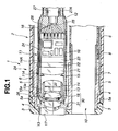
- the following describes a specific configuration of the distal end portion 2A which includes the image pickup apparatus 1.
- the image pickup unit 11 of the present embodiment is configured to include a lens unit 11A having a variable aperture unit 30 described in a later section, an image pickup device 23 such as a CCD (Charge Coupled Device), a CMOS (Complementary Metal-Oxide Semiconductor), and a circuit substrate 24.
- an image pickup device 23 such as a CCD (Charge Coupled Device), a CMOS (Complementary Metal-Oxide Semiconductor), and a circuit substrate 24.
- the first lens group 18, which may have two objective lenses including the distal end lens 17, is held by the first lens frame 13.
- the third lens frame 14 holds the third lens group 20, which may include two lenses.
- the fourth lens frame 15 holds the fourth lens 21 which may be a single objective lens.
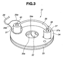
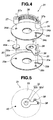
- variable aperture mechanism 31 of the variable aperture unit 30 The following describes a specific configuration of the variable aperture mechanism 31 of the variable aperture unit 30 according to the present embodiment with reference to Figs. 3 to 6 .
- the fixed pin 40 projecting on the side of the first substrate 33 is fitted into the fixed pin hole 33d of the first substrate 33.
- the fixed pin 40 projecting on the side of the second substrate 34 is passed through the fixed pin hole 34d of the second substrate 34.
- the fixed pin 38 projecting on the side of the second substrate 34 is formed with sufficient length to pass through and engage with the through hole 37a in the connecting portion 37 of the ion conducting actuator 36.
- the bifocal lens 19 of the variable aperture unit 30 is provided on the emission surface side of the variable aperture mechanism 31.
- a variable aperture configuration in which the bifocal lens 19 is, for example, provided on the incident surface side of the variable aperture mechanism 31 may be used. When this configuration is used, it may be necessary to move or include other objective lenses or the like for optical reasons.
- variable aperture unit 30 The following describes a second embodiment of the variable aperture unit 30 with reference to Fig. 10 to Fig. 13 .
- the first driving pin 40 and the second driving pin 48 are cylindrical and may be integrated with the respective discs 40a and 48a or provided as separate entities.
- the first and second driving pins 40 and 48 project from the front and rear surfaces of the discs 40a and 48a.
- the first driving pin 40 projecting on the side of the first substrate 33A passes through the slit 33b of the first substrate 33A.
- the first driving pin 40 projecting on the side of the third substrate 41 passes through the slit 41b in the third substrate 41, passes through the through hole 43c of the second aperture blade portion 43 and the slit 34b of the second substrate 34A, and then passes through the through hole 37a of the connecting portion 37 of the ion conducting actuator 36.
- the worker then installs the second aperture blade portion 43, the spacer-receiving portions 46 and 47, and the second driving pin 48 in the stated order between the third substrate 41 and the second substrate 34A.
- the worker fits, in a similar manner to in the first embodiment, the first driving pin 40 and the second driving pin 48 protruding from the respective slits 34b in the second substrate 34A into the two through holes 37a of the connecting portions 37 included in the ion conducting actuator 36.
- variable aperture mechanism 31A The following describes operations of the variable aperture mechanism 31A with reference to Fig. 12 and Fig. 13 .
- first driving pin 40 and the second driving pin 48 passing through the connecting portion 37 move in the slits 34b, 33b, and 41b in an opposite direction to the movement at aperture reduction.
- first aperture blade portion 42 pivots around the rotation pin 42b to a position away from the fixed aperture openings 34a, 33a and 41a of the substrates 33A, 34A and 41
- second aperture blade portion 43 pivots around the rotation pin 43b to a position away from the fixed aperture openings 34a, 33a and 41a of the substrates 33A, 34A and 41, as shown in Fig. 13 .
- Some types of conventional image pickup apparatus include a zoom mechanism.
- an ion conducting actuator is used as the zoom mechanism actuator included in the image pickup apparatus, a range of movement in a moving lens frame is small due to the small amount of displacement in the ion conducting actuator.
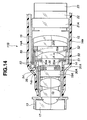
- An external circumferential section of the second ion conducting actuator 52 is fixed to an extension portion 14e of the third lens frame 14 behind the moving lens frame 50 and in front of the objective lenses 20b as shown in Fig. 14 .
- a fulcrum for displacement of the second ion conducting actuator 52 is positioned outside the external diameter of the objective lens 20a held by the moving lens frame 50.
- the extension portion 14e of the third lens frame 14 serves to strengthen a fixing state of the second ion conducting actuator 52.
- the ion conducting actuators 51 and 52 have similar ring-form plate configurations, and the first ion conducting actuator 51 includes, for instance, an opening 51a and a plurality of deformation portions 57 as shown in Fig. 16 .
- the plurality of deformation portions 57 is configured to include a plurality of radial cuts 56 on lines extending from the central axis of the opening 51a towards external circumference.
- a circular portion indicated by the broken line tying ends of the plurality of cuts 56 is a displacement line 58 indicating a deformation start line where the deformation of the plurality of deformation portions 57 begins and the inner peripheral portion is an active portion.
- a signal line 55 is connected to a proximal end of the cable connection substrate 54.
- the signal line 55 passes into the image pickup unit 11B and then through the signal cable 27.
- the ion conducting actuators 51 and 52 of Fig. 15 are connected in parallel via the signal lines 53a and 53b to a driving controller 60 in the video processor, as shown in the circuit configuration for driving the ion conducting actuators 51 and 52 of Fig. 15 .
- the moving lens frame 50 is moved by fixing the ion conducting actuators 51 and 52 to the third lens frame 14 and causing deformation in the plurality of deformation portions 57.
- the moving lens frame 50 is moved by fixing the first ion conducting actuator 51A and the second ion conducting actuator 52A to the moving lens frame 50 and the objective lens 20a, as shown in Fig. 17 .
- a moving lens frame 50 is provided in the image pickup unit 11D.
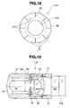
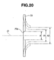
- the objective lens 20a is held in the moving lens frame 50 so as to be in contact with the active portion of the variable aperture deformation portion when the ion conducting actuator 70 with the aperture function is driven.
Landscapes
- Health & Medical Sciences (AREA)
- Life Sciences & Earth Sciences (AREA)
- Physics & Mathematics (AREA)
- Surgery (AREA)
- Optics & Photonics (AREA)
- Biomedical Technology (AREA)
- Animal Behavior & Ethology (AREA)
- Radiology & Medical Imaging (AREA)
- Nuclear Medicine, Radiotherapy & Molecular Imaging (AREA)
- Engineering & Computer Science (AREA)
- Biophysics (AREA)
- Heart & Thoracic Surgery (AREA)
- Medical Informatics (AREA)
- Molecular Biology (AREA)
- Pathology (AREA)
- General Health & Medical Sciences (AREA)
- Public Health (AREA)
- Veterinary Medicine (AREA)
- General Physics & Mathematics (AREA)
- Astronomy & Astrophysics (AREA)
- Endoscopes (AREA)
- Instruments For Viewing The Inside Of Hollow Bodies (AREA)
- Diaphragms For Cameras (AREA)
Claims (12)
- Bildaufnahmevorrichtung (1) mit einer Linseneinheit (11A), die dazu eingerichtet ist, eine Mehrzahl von Linsen (18, 19, 20, 21; 19A, 20a, 20b) aufzuweisen, und einem variablen Blendenmechanismus (31; 31A), der betreibbar ist, um einen Blendenöffnungsdurchmesser zu variieren,
wobei die Bildaufnahmevorrichtung in der Linseneinheit eine variable Blendeneinheit (30; 30A) umfasst, die durch Integration des variablen Blendenmechanismus (31; 31A) und einer Linse (19; 19A) der Mehrzahl von Linsen (18, 19, 20, 21; 19A, 20a, 20b) der Linseneinheit (11A) unter Verwendung eines Fixierabschnitts (35) aufgebaut ist,
dadurch gekennzeichnet, dass der variable Blendenmechanismus (31; 31A) einen ionenleitenden Aktuator (36) aufweist, der betreibbar ist, um einen Blendenöffnungsdurchmesser zu variieren. - Bildaufnahmevorrichtung (1) nach Anspruch 1, wobei die variable Blendeneinheit (30; 30A) durch Positionsabgleich einer optischen Achse der Linse (19; 19A) mit einer Zentralachse des Blendenöffnungsdurchmessers, wenn sich der Blendenöffnungsdurchmesser des variablen Blendenmechanismus (31; 31A) in einem abgeblendeten Zustand befindet, und Fixieren des variable Blendenmechanismus (31; 31A) und der Linse (19; 19A) in einem positionsabgeglichenen Zustand unter Verwendung des Fixierabschnitts (35) aufgebaut ist.
- Bildaufnahmevorrichtung (1) nach Anspruch 1 oder 2, wobei die an den variablen Blendenmechanismus (31) fixierte Linse (19) eine bifokale Linse ist.
- Bildaufnahmevorrichtung (1) nach Anspruch 1, wobei der variable Blendenmechanismus (31; 31A) einen Blendenlamellenabschnitt (32; 42, 43) aufweist, der betreibbar ist, um durch den ionenleitenden Aktuator (36) gedreht zu werden, und eine Blendenöffnung (32a; 42a, 43a) aufweist.
- Bildaufnahmevorrichtung (1) nach Anspruch 1, wobei der variable Blendenmechanismus (31A) ein Paar Blendenlamellenabschnitte (42, 43) aufweist, von denen jeder betreibbar ist, um durch den ionenleitenden Aktuator (36) gedreht zu werden, und eine halbkreisförmige Blendenöffnung (42a, 43a) aufweist.
- Bildaufnahmevorrichtung (1) umfassend:eine Linseneinheit (11A), die eine Mehrzahl Linsen (18, 19A, 20a 20b, 21A) und einen beweglichen Linsenrahmen (50) aufweist, der mindestens eine Linse (20a) der Mehrzahl von Linsen (18, 19A, 20a, 20b, 21A) hält, um eine Bewegung der mindestens einen Linse (20a) in Richtung einer optischen Achse zu ermöglichen;gekennzeichnet durch einen Zoommechanismus mit einem ionenleitenden Aktuator (51, 52; 51A, 52A; 70), der betreibbar ist, um den in der Linseneinheit (11A) vorgesehenen beweglichen Linsenrahmen (50) zu bewegen.
- Bildaufnahmevorrichtung (1) nach Anspruch 6, wobei der ionenleitende Aktuator (51, 52; 51A, 52A) ein ringähnlicher Plattenkörper ist und eine Verformungseigenschaft gemäß eines Stroms aufweist, der durch elektrisch mit einer Vorder- bzw. einer Rückseite des Plattenkörpers verbundene Signalleitungen geführt wird, und der bewegliche Linsenrahmen (50) sich in der Richtung der optischen Achse als Ergebnis der durch Führen des Stroms bewirkten Deformation bewegt.
- Bildaufnahmevorrichtung (1) nach Anspruch 6, wobei die Linseneinheit (11A) aufweist:einen ersten ionenleitenden Aktuator (51; 51A), der vor dem beweglichen Linsenrahmen (50) angeordnet ist und betreibbar ist, um den beweglichen Linsenrahmen (50) in Richtung einer proximalen Endseite der Linseneinheit (11A) zugewandten Endseite zu bewegen; undeinen zweiten ionenleitenden Aktuator (52; 52A), der hinter dem beweglichen Linsenrahmen (50) angeordnet ist und betreibbar ist, um den beweglichen Linsenrahmen (50) in Richtung einer distalen Endseite der Linseneinheit (11A) zu bewegen.
- Bildaufnahmevorrichtung (1) nach Anspruch 8, ferner umfassend:einen Schalter (61), der betreibbar ist, um eine Polarität eines in dem ersten ionenleitenden Aktuator (51, 51A) und in dem zweiten ionenleitenden Aktuator (52; 52A) fließenden Antriebsstroms umzukehren, wobeider erste ionenleitende Aktuator (51; 51A) und der zweite ionenleitende Aktuator (52; 52A) durch den Schalter (61) basierend auf einem Schalten der Polarität des in den entsprechenden ionenleitenden Aktuatoren (51, 52; 51A, 52A) fließenden Antriebsstroms den beweglichen Linsenrahmen (50) in Richtung der proximalen Endseite oder der abgewandten Endseite bewegen.
- Bildaufnahmevorrichtung (1) nach Anspruch 9, wobei
der erste ionenleitende Aktuator (51; 51A) und der zweite ionenleitende Aktuator (52; 52A) ringähnliche Plattenkörper mit zentralen Öffnungsabschnitten (51a) sind, und
ein äußerer Umfangsabschnitt jedes ionenleitenden Aktuators (51, 52; 51A, 52A) an einem Linsenrahmen (14) fixiert ist, der den beweglichen Linsenrahmen (50) bewegbar trägt. - Bildaufnahmevorrichtung (1) nach Anspruch 10, wobei
Stützpunkte des ersten ionenleitenden Aktuators (51; 51A) und des zweiten ionenleitenden Aktuators (52; 52A) außerhalb eines äußeren Durchmessers der in dem beweglichen Linsenrahmen (50) gehaltenen Linse (20a) angeordnet sind. - Bildaufnahmevorrichtung (1) nach Anspruch 9, wobei
der erste ionenleitende Aktuator (51; 51A) und der zweite ionenleitende Aktuator (52; 52A) ringförmige Plattenkörper mit zentralen Öffnungsabschnitten sind, und
ein Abschnitt in der Höhe der Öffnungsabschnitte jedes ionenleitenden Aktuators (51, 52; 51A, 52A) an dem beweglichen Linsenrahmen (50) oder der in dem beweglichen Linsenrahmen (50) gehaltenen Linse (20a) fixiert ist.
Applications Claiming Priority (2)
| Application Number | Priority Date | Filing Date | Title |
|---|---|---|---|
| JP2006071656A JP4800805B2 (ja) | 2006-03-15 | 2006-03-15 | 撮像装置 |
| PCT/JP2007/052644 WO2007108257A1 (ja) | 2006-03-15 | 2007-02-14 | 撮像装置 |
Publications (3)
| Publication Number | Publication Date |
|---|---|
| EP1994873A1 EP1994873A1 (de) | 2008-11-26 |
| EP1994873A4 EP1994873A4 (de) | 2010-04-07 |
| EP1994873B1 true EP1994873B1 (de) | 2014-01-15 |
Family
ID=38522294
Family Applications (1)
| Application Number | Title | Priority Date | Filing Date |
|---|---|---|---|
| EP07714197.6A Not-in-force EP1994873B1 (de) | 2006-03-15 | 2007-02-14 | Abbildungseinrichtung |
Country Status (4)
| Country | Link |
|---|---|
| US (1) | US7982974B2 (de) |
| EP (1) | EP1994873B1 (de) |
| JP (1) | JP4800805B2 (de) |
| WO (1) | WO2007108257A1 (de) |
Families Citing this family (17)
| Publication number | Priority date | Publication date | Assignee | Title |
|---|---|---|---|---|
| CN101652681B (zh) * | 2007-03-31 | 2015-09-09 | 皇家飞利浦电子股份有限公司 | 光学活检设备 |
| JP5041855B2 (ja) * | 2007-04-09 | 2012-10-03 | イーメックス株式会社 | アクチュエータ体および絞り機構 |
| US8467138B2 (en) | 2009-01-21 | 2013-06-18 | Olympus Corporation | Optical element and optical unit using the same |
| JP5275887B2 (ja) * | 2009-04-22 | 2013-08-28 | オリンパス株式会社 | 光学ユニット |
| US7961401B1 (en) * | 2009-12-23 | 2011-06-14 | Ge Inspection Technologies, Lp | System for providing two position zoom-focus |
| CN102662203B (zh) * | 2012-05-14 | 2015-05-13 | 北京国科世纪激光技术有限公司 | 一种光阑 |
| JP5722513B1 (ja) * | 2013-09-25 | 2015-05-20 | オリンパスメディカルシステムズ株式会社 | 電気ユニット、及びこれを搭載した内視鏡 |
| KR20150085611A (ko) * | 2014-01-16 | 2015-07-24 | 삼성전기주식회사 | 카메라 모듈 |
| DE102014204784A1 (de) * | 2014-03-14 | 2015-09-17 | Olympus Winter & Ibe Gmbh | Endoskop mit distaler elektrischer Durchführung und Verfahren zur Montage eines Endoskops |
| DE102014208652A1 (de) * | 2014-05-08 | 2015-11-12 | Olympus Winter & Ibe Gmbh | Videoendoskop |
| US9838576B2 (en) | 2015-08-31 | 2017-12-05 | Panasonic Corporation | Endoscope |
| JP6843996B2 (ja) * | 2017-07-12 | 2021-03-17 | オリンパス株式会社 | 内視鏡及び撮像ユニット |
| WO2021181530A1 (ja) * | 2020-03-10 | 2021-09-16 | オリンパス株式会社 | 内視鏡、内視鏡の先端枠部材および内視鏡の挿入部 |
| TWI732541B (zh) * | 2020-04-27 | 2021-07-01 | 大立光電股份有限公司 | 成像透鏡組與成像鏡頭模組 |
| CN116113877B (zh) * | 2020-07-22 | 2026-01-23 | 华为技术有限公司 | 单片式致动器及包括单片式致动器的可调光圈单元 |
| WO2022029969A1 (ja) * | 2020-08-06 | 2022-02-10 | オリンパス株式会社 | 撮像ユニット、挿入機器 |
| CN117957492A (zh) * | 2021-09-16 | 2024-04-30 | 华为技术有限公司 | 具有集成自动对焦和可变光圈的设备 |
Family Cites Families (17)
| Publication number | Priority date | Publication date | Assignee | Title |
|---|---|---|---|---|
| US3883228A (en) * | 1973-07-09 | 1975-05-13 | Minnesota Mining & Mfg | Variable magnification zoom lens |
| US4445764A (en) * | 1980-12-02 | 1984-05-01 | Canon Kabushiki Kaisha | Light measuring device for a single lens reflex camera |
| JPH07119893B2 (ja) * | 1986-09-22 | 1995-12-20 | オリンパス光学工業株式会社 | 内視鏡光学系 |
| JP3092951B2 (ja) * | 1990-06-18 | 2000-09-25 | オリンパス光学工業株式会社 | 内視鏡用絞り装置 |
| JPH07140401A (ja) * | 1993-11-22 | 1995-06-02 | Olympus Optical Co Ltd | 光学機器の絞り装置 |
| JP3193562B2 (ja) * | 1994-03-18 | 2001-07-30 | オリンパス光学工業株式会社 | 圧電アクチュエータ |
| JP3636252B2 (ja) * | 1996-05-24 | 2005-04-06 | 富士写真フイルム株式会社 | 可変絞り装置および内視鏡 |
| JP3601905B2 (ja) | 1996-05-27 | 2004-12-15 | フジノン株式会社 | 固定焦点超小型カメラ |
| JPH09322566A (ja) * | 1996-06-04 | 1997-12-12 | Olympus Optical Co Ltd | 圧電アクチュエータ |
| US5970260A (en) * | 1997-09-10 | 1999-10-19 | Konica Corporation | Camera equipped with zoom lens |
| WO2004074354A1 (ja) | 2003-02-19 | 2004-09-02 | Eamex Corporation | 筒状導電性高分子成形物 |
| JP4405824B2 (ja) * | 2003-02-19 | 2010-01-27 | イーメックス株式会社 | 筒状導電性高分子成形物とその製造方法及びこれを用いたアクチュエータ並びにその用途 |
| JP2004248877A (ja) * | 2003-02-20 | 2004-09-09 | Pentax Corp | 可変絞り付き内視鏡 |
| JP4574993B2 (ja) * | 2004-01-16 | 2010-11-04 | オリンパス株式会社 | 病変検出システム |
| JP2006071656A (ja) | 2004-08-31 | 2006-03-16 | Canon Inc | 焦点検出装置 |
| JP2007003815A (ja) * | 2005-06-23 | 2007-01-11 | Fujifilm Holdings Corp | 移動規定装置、レンズ移動装置、および撮影装置 |
| JP4994639B2 (ja) * | 2005-11-01 | 2012-08-08 | オリンパス株式会社 | 光学絞り装置 |
-
2006
- 2006-03-15 JP JP2006071656A patent/JP4800805B2/ja not_active Expired - Fee Related
-
2007
- 2007-02-14 EP EP07714197.6A patent/EP1994873B1/de not_active Not-in-force
- 2007-02-14 WO PCT/JP2007/052644 patent/WO2007108257A1/ja not_active Ceased
-
2008
- 2008-09-10 US US12/207,953 patent/US7982974B2/en not_active Expired - Fee Related
Also Published As
| Publication number | Publication date |
|---|---|
| US7982974B2 (en) | 2011-07-19 |
| JP4800805B2 (ja) | 2011-10-26 |
| US20090010140A1 (en) | 2009-01-08 |
| EP1994873A4 (de) | 2010-04-07 |
| EP1994873A1 (de) | 2008-11-26 |
| WO2007108257A1 (ja) | 2007-09-27 |
| JP2007244604A (ja) | 2007-09-27 |
Similar Documents
| Publication | Publication Date | Title |
|---|---|---|
| EP1994873B1 (de) | Abbildungseinrichtung | |
| CN102483503B (zh) | 摄像单元 | |
| US5993381A (en) | Operating unit for an endoscope | |
| JP4898614B2 (ja) | 撮像装置 | |
| CN103068295B (zh) | 内窥镜用摄像装置 | |
| US12611090B2 (en) | Endoscopic device with USB port and powered accessories | |
| WO2007123129A1 (ja) | 内視鏡システム及びレンズユニット | |
| US10441137B2 (en) | Image pickup unit and endoscope | |
| US20240156334A1 (en) | Endoscope bending operation mechanism and endoscope | |
| JP4847157B2 (ja) | 内視鏡 | |
| JP3719100B2 (ja) | 内視鏡の撮像装置 | |
| WO2015029718A1 (ja) | 挿入機器及び内視鏡 | |
| US20140247333A1 (en) | Endoscope and method for manufacturing the same | |
| US20240268634A1 (en) | Endoscope | |
| WO2020008673A1 (ja) | 内視鏡 | |
| JP2000210249A (ja) | 対物レンズ移動機構付き内視鏡 | |
| US10602915B2 (en) | Trans-platform apparatus and use thereof | |
| CN117045177A (zh) | 内窥镜 | |
| WO2012017861A1 (ja) | 内視鏡 | |
| JP5242041B2 (ja) | 内視鏡 | |
| JP4042284B2 (ja) | 内視鏡の観察ユニット装着機構 | |
| JP2002122795A (ja) | 内視鏡装置 | |
| US10271718B2 (en) | Image pickup unit and endoscope | |
| JP2001033710A (ja) | 拡大観察用内視鏡 | |
| CN118717006A (zh) | 内窥镜 |
Legal Events
| Date | Code | Title | Description |
|---|---|---|---|
| PUAI | Public reference made under article 153(3) epc to a published international application that has entered the european phase |
Free format text: ORIGINAL CODE: 0009012 |
|
| 17P | Request for examination filed |
Effective date: 20080905 |
|
| AK | Designated contracting states |
Kind code of ref document: A1 Designated state(s): DE FR GB |
|
| DAX | Request for extension of the european patent (deleted) | ||
| RBV | Designated contracting states (corrected) |
Designated state(s): DE FR GB |
|
| A4 | Supplementary search report drawn up and despatched |
Effective date: 20100309 |
|
| 17Q | First examination report despatched |
Effective date: 20100701 |
|
| RTI1 | Title (correction) |
Free format text: IMAGE PICKUP APPARATUS |
|
| GRAP | Despatch of communication of intention to grant a patent |
Free format text: ORIGINAL CODE: EPIDOSNIGR1 |
|
| INTG | Intention to grant announced |
Effective date: 20130829 |
|
| GRAS | Grant fee paid |
Free format text: ORIGINAL CODE: EPIDOSNIGR3 |
|
| GRAA | (expected) grant |
Free format text: ORIGINAL CODE: 0009210 |
|
| AK | Designated contracting states |
Kind code of ref document: B1 Designated state(s): DE FR GB |
|
| REG | Reference to a national code |
Ref country code: GB Ref legal event code: FG4D |
|
| REG | Reference to a national code |
Ref country code: DE Ref legal event code: R096 Ref document number: 602007034780 Country of ref document: DE Effective date: 20140227 |
|
| REG | Reference to a national code |
Ref country code: DE Ref legal event code: R097 Ref document number: 602007034780 Country of ref document: DE |
|
| PLBE | No opposition filed within time limit |
Free format text: ORIGINAL CODE: 0009261 |
|
| REG | Reference to a national code |
Ref country code: FR Ref legal event code: ST Effective date: 20141031 |
|
| STAA | Information on the status of an ep patent application or granted ep patent |
Free format text: STATUS: NO OPPOSITION FILED WITHIN TIME LIMIT |
|
| 26N | No opposition filed |
Effective date: 20141016 |
|
| GBPC | Gb: european patent ceased through non-payment of renewal fee |
Effective date: 20140415 |
|
| PG25 | Lapsed in a contracting state [announced via postgrant information from national office to epo] |
Ref country code: GB Free format text: LAPSE BECAUSE OF NON-PAYMENT OF DUE FEES Effective date: 20140415 Ref country code: FR Free format text: LAPSE BECAUSE OF NON-PAYMENT OF DUE FEES Effective date: 20140317 |
|
| REG | Reference to a national code |
Ref country code: DE Ref legal event code: R097 Ref document number: 602007034780 Country of ref document: DE Effective date: 20141016 |
|
| REG | Reference to a national code |
Ref country code: DE Ref legal event code: R082 Ref document number: 602007034780 Country of ref document: DE Representative=s name: WUESTHOFF & WUESTHOFF, PATENTANWAELTE PARTG MB, DE Ref country code: DE Ref legal event code: R081 Ref document number: 602007034780 Country of ref document: DE Owner name: OLYMPUS CORPORATION, JP Free format text: FORMER OWNER: OLYMPUS MEDICAL SYSTEMS CORP., TOKYO, JP |
|
| PGFP | Annual fee paid to national office [announced via postgrant information from national office to epo] |
Ref country code: DE Payment date: 20170207 Year of fee payment: 11 |
|
| REG | Reference to a national code |
Ref country code: DE Ref legal event code: R119 Ref document number: 602007034780 Country of ref document: DE |
|
| PG25 | Lapsed in a contracting state [announced via postgrant information from national office to epo] |
Ref country code: DE Free format text: LAPSE BECAUSE OF NON-PAYMENT OF DUE FEES Effective date: 20180901 |