EP1994877A1 - Medizinische bildverarbeitungsvorrichtung und medizinisches bildverarbeitungsverfahren - Google Patents
Medizinische bildverarbeitungsvorrichtung und medizinisches bildverarbeitungsverfahren Download PDFInfo
- Publication number
- EP1994877A1 EP1994877A1 EP07714979A EP07714979A EP1994877A1 EP 1994877 A1 EP1994877 A1 EP 1994877A1 EP 07714979 A EP07714979 A EP 07714979A EP 07714979 A EP07714979 A EP 07714979A EP 1994877 A1 EP1994877 A1 EP 1994877A1
- Authority
- EP
- European Patent Office
- Prior art keywords
- pixel
- inappropriate
- image
- image processing
- edge
- Prior art date
- Legal status (The legal status is an assumption and is not a legal conclusion. Google has not performed a legal analysis and makes no representation as to the accuracy of the status listed.)
- Granted
Links
Images


Classifications
-
- A—HUMAN NECESSITIES
- A61—MEDICAL OR VETERINARY SCIENCE; HYGIENE
- A61B—DIAGNOSIS; SURGERY; IDENTIFICATION
- A61B1/00—Instruments for performing medical examinations of the interior of cavities or tubes of the body by visual or photographical inspection, e.g. endoscopes; Illuminating arrangements therefor
- A61B1/04—Instruments for performing medical examinations of the interior of cavities or tubes of the body by visual or photographical inspection, e.g. endoscopes; Illuminating arrangements therefor combined with photographic or television appliances
-
- G—PHYSICS
- G06—COMPUTING OR CALCULATING; COUNTING
- G06T—IMAGE DATA PROCESSING OR GENERATION, IN GENERAL
- G06T5/00—Image enhancement or restoration
- G06T5/20—Image enhancement or restoration using local operators
- G06T5/30—Erosion or dilatation, e.g. thinning
-
- G—PHYSICS
- G06—COMPUTING OR CALCULATING; COUNTING
- G06T—IMAGE DATA PROCESSING OR GENERATION, IN GENERAL
- G06T5/00—Image enhancement or restoration
- G06T5/70—Denoising; Smoothing
-
- G—PHYSICS
- G06—COMPUTING OR CALCULATING; COUNTING
- G06T—IMAGE DATA PROCESSING OR GENERATION, IN GENERAL
- G06T5/00—Image enhancement or restoration
- G06T5/77—Retouching; Inpainting; Scratch removal
-
- G—PHYSICS
- G06—COMPUTING OR CALCULATING; COUNTING
- G06T—IMAGE DATA PROCESSING OR GENERATION, IN GENERAL
- G06T7/00—Image analysis
- G06T7/10—Segmentation; Edge detection
- G06T7/13—Edge detection
-
- G—PHYSICS
- G06—COMPUTING OR CALCULATING; COUNTING
- G06T—IMAGE DATA PROCESSING OR GENERATION, IN GENERAL
- G06T7/00—Image analysis
- G06T7/10—Segmentation; Edge detection
- G06T7/155—Segmentation; Edge detection involving morphological operators
-
- H—ELECTRICITY
- H04—ELECTRIC COMMUNICATION TECHNIQUE
- H04N—PICTORIAL COMMUNICATION, e.g. TELEVISION
- H04N1/00—Scanning, transmission or reproduction of documents or the like, e.g. facsimile transmission; Details thereof
- H04N1/40—Picture signal circuits
- H04N1/409—Edge or detail enhancement; Noise or error suppression
- H04N1/4097—Removing errors due external factors, e.g. dust, scratches
-
- G—PHYSICS
- G06—COMPUTING OR CALCULATING; COUNTING
- G06T—IMAGE DATA PROCESSING OR GENERATION, IN GENERAL
- G06T2207/00—Indexing scheme for image analysis or image enhancement
- G06T2207/10—Image acquisition modality
- G06T2207/10068—Endoscopic image
-
- G—PHYSICS
- G06—COMPUTING OR CALCULATING; COUNTING
- G06T—IMAGE DATA PROCESSING OR GENERATION, IN GENERAL
- G06T2207/00—Indexing scheme for image analysis or image enhancement
- G06T2207/30—Subject of image; Context of image processing
- G06T2207/30004—Biomedical image processing
Definitions
- the present invention relates to a medical image processing apparatus and a medical image processing method for performing image processing on a medical input image.
- a medical instrument having an image pickup function such as an endoscope apparatus
- an elongated insertion portion is inserted into a body cavity, and an image of an organ in the body cavity is picked up by image pickup means provided at a distal end portion of the insertion portion.
- image pickup means provided at a distal end portion of the insertion portion.
- Endoscope images may be subjected to image processing such as color enhancement which improves visibility at diagnosis by an image processing apparatus or the like.
- An endoscope image obtained by image pickup may include a halation portion, dark portion, or the like, and an accurate image processing result may not be obtained.
- the above-described image processing apparatus only removes image data of a portion from which an accurate image processing result is not obtained and has no consideration for replenishment of image data for the portion.
- the present invention has been made in consideration of the above-described problem, and has an object to provide a medical image processing apparatus and a medical image processing method capable of calculating and replenishing image data of a portion from which an accurate image processing result is not obtained.
- a medical image processing apparatus is a medical image processing apparatus which performs image processing on a medical input image, includes: pixel extraction means for extracting an inappropriate pixel satisfying a predetermined condition in the input image, replacing pixel information calculation means for calculating replacing information with which pixel information of the inappropriate pixel is to be replaced, based on pixel information of a predetermined region including the extracted inappropriate pixel or adjacent to the extracted inappropriate pixel, and replaced image generation means for replacing the pixel information of the inappropriate pixel in the input image with the replacing information and generating a replaced image.
- a medical image processing method is a medical image processing method for performing image processing on a medical input image, includes: a pixel extraction step of extracting an inappropriate pixel satisfying a predetermined condition in the input image, a replacing pixel information calculation step of calculating replacing information with which pixel information of the inappropriate pixel is to be replaced, based on pixel information of a predetermined region including the extracted inappropriate pixel or adjacent to the extracted inappropriate pixel, and a replaced image generation step of generating a replaced image obtained by replacing the pixel information of the inappropriate pixel in the input image with the calculated replacing information.
- An image processing apparatus extracts, e.g., a halation pixel, a pixel in which only an R signal intensity value is saturated (hereinafter referred to as an R saturated pixel), a missing pixel, or the like present in an inputted medical image.
- the image processing apparatus is capable of calculating new pixel information based on pixel information such as a signal intensity value of a portion around the pixel and generating an image obtained by replacing pixel information of the pixel with the calculated pixel information.
- the image processing apparatus is configured to be capable of altering, e.g., the halation pixel, R saturated pixel, missing pixel, or the like included in an input image to a pixel suitable for three-dimensional image generation processing.
- Medical images have recently been subjected to a process of converting a two-dimensional image into a three-dimensional image to find a lesioned part.
- Such a three-dimensional image is generated by adding, to each of pixels constituting a two-dimensional picked-up image, three-dimensional coordinates based on luminance of each of the pixels.
- Methods for generating a three-dimensional image include a method for converting a coordinate system of two-dimensional endoscope image into a coordinate system defining a Z direction as a luminal direction and a ⁇ direction as a circumferential direction which takes a position of a darkest portion in the two-dimensional endoscope image as a center position and generating a developed view.
- a pixel such as a halation pixel, R saturated pixel, or missing pixel which has abnormal luminance may significantly deviate from values supposed to be obtained.
- An image processing apparatus of the present embodiment is configured to be capable of altering a halation pixel or the like included in an input image to a pixel suitable for three-dimensional image generation processing and generating a three-dimensional image based on an altered image.
- a halation pixel or the like included in an input image
- a pixel suitable for three-dimensional image generation processing and generating a three-dimensional image based on an altered image.
- an R saturated pixel will be referred to as an inappropriate pixel in a following description.
- Fig. 1 is a diagram of a schematic configuration of the image processing apparatus according to the present embodiment.
- an image processing apparatus 1 is composed of an extraction portion 2, a calculation portion 3, a replacement portion 4, and a three-dimensional image generation portion 5.
- the extraction portion 2, calculation portion 3, replacement portion 4, and three-dimensional image generation portion 5 each has a plurality of electronic devices including a CPU.
- the extraction portion 2 as pixel extraction means extracts an inappropriate pixel included in an input image.
- the calculation portion 3 as replacing pixel information calculation means calculates replacing information with which pixel information at the extracted inappropriate pixel is to be replaced.
- the replacement portion 4 as replaced image output means generates a replaced image obtained by replacing the pixel information at the inappropriate pixel with the calculated replacing information.
- the three-dimensional image generation portion 5 as three-dimensional image generation means generates a three-dimensional image based on the generated replaced image.
- An input image inputted to the image processing apparatus 1 is a picked-up image picked up by an endoscope apparatus 6 having a CCD camera and the like.
- the picked-up image is an endoscope image obtained by picking up an image of an interior of a body cavity such as a large intestine and is composed of R, G, and B color signals.
- the color signals have a red signal intensity value R, a green signal intensity value G, and a blue signal intensity value B as pieces of pixel information.
- Fig. 2 shows an example of a relationship between R, G, and B signal intensities at a certain row (or a certain column) of a two-dimensional x-y picked-up image and a pixel position.
- an ordinate axis represents a signal intensity while an abscissa axis represents a pixel position at a certain row (or a certain column) in a picked-up image, e.g., along an x direction (or a y direction).
- a ratio among a red signal intensity value R, a green signal intensity value G, and a blue signal intensity value B is almost same at pixels.
- red signal intensity value R Since absorption of light in a living mucous membrane on a surface of an interior of a body cavity depends on the amount of hemoglobin bound to oxygen, a red signal intensity value R is highest. For the reason, only red signal intensity value R is saturated in some living mucous membrane images.
- a pixel whose red signal intensity value R is saturated shown in Fig. 2 e.g., a pixel having a signal intensity of not less than 255, is an inappropriate pixel.
- the image processing apparatus 1 extracts such an inappropriate pixel included in a picked-up image, calculates replacing information with which pixel information at the inappropriate pixel is to be replaced, and generates a three-dimensional image based on a replaced image generated by replacing the pixel information at the inappropriate pixel with the calculated replacing information.
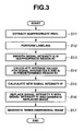
- Fig. 3 is a flow chart for an example of a flow of the image processing in the image processing apparatus 1. A process to be described below starts when a picked-up image is inputted to the image processing apparatus 1.
- the image processing apparatus 1 extracts inappropriate pixels in the inputted picked-up image (step S11).
- the extraction of the inappropriate pixels is performed by the extraction portion 2.
- Pixels of the two-dimensional picked-up image are sequentially scanned from, e.g., a pixel (1, 1), and it is determined whether or not a red signal intensity value Rij (i, j: coordinates of a pixel in the picked-up image) is equal to or more than a predetermined threshold value, thereby extracting the inappropriate pixels.
- Rij red signal intensity value
- the predetermined threshold value is a signal intensity value of 255, and a pixel whose red signal intensity value Rij shown in Fig. 2 is not less than 255 is determined as an inappropriate pixel.
- the predetermined threshold value may be set to a value depending on an inappropriate pixel desired to be extracted.
- the image processing apparatus 1 labels the extracted inappropriate pixels (step S 12).
- the labeling is performed by the extraction portion 2.
- the two-dimensional picked-up image is scanned sequentially from, e.g., the pixel (1, 1), and a same attribute such as a number, i.e., a same label is attached to adjacent inappropriate pixels.
- a label having a different value is assigned to each region composed of a plurality of inappropriate pixels. Further processing is performed for each of the labeled regions.
- a region composed of a plurality of inappropriate pixels will be referred to as an inappropriate region hereinafter.
- a same label is attached to the inappropriate pixels constituting the inappropriate region R1.
- the image processing apparatus 1 smoothes a green signal intensity value Gij of each pixel in the inappropriate region R1 and calculates a smoothed signal intensity value Gs which is a smoothed signal intensity (step S 13).
- the smoothing is performed by the calculation portion 3.
- Step S13 constitutes smoothing means.
- the smoothing is a process of sequentially replacing the green signal intensity value Gij at an object pixel as which each of the inappropriate pixels belonging to the inappropriate region is regarded with, e.g., an average value of signal intensity values within a range of eight surrounding pixels.
- a range for average value calculation in the smoothing is not limited to a range of eight surrounding pixels and can be freely changed depending on a desired smoothing degree.
- the smoothing is sequentially performed on the inappropriate pixels belonging to each of the labeled inappropriate regions.
- object pixels to be subjected to the smoothing are Gij in the inappropriate region R1.
- the image processing apparatus 1 calculates an average value ( ⁇ _R) for a red signal intensity value R as a first average signal intensity value and an average value ( ⁇ _G) for a green signal intensity value G as a second average signal intensity value in a predetermined region (step S 14).
- the average values are calculated by the calculation portion 3.
- Step S 14 constitutes averaging means.
- the predetermined region is a region which includes at least one pixel adjacent to an inappropriate region with an object label and is composed of pixels that are not inappropriate pixels.
- the region is composed of a possible maximum number of pixels (e.g., 5 ⁇ 5 pixels). That is, the predetermined region is a region in a neighborhood of an inappropriate region which is tangent to pixels belonging to the inappropriate region.
- a size of the predetermined region is not limited to 5 ⁇ 5 pixels and can be freely changed depending on an inputted picked-up image.
- Fig. 2 shows a predetermined region R2.
- the average value ( ⁇ _R) for a red signal intensity value R and the average value ( ⁇ _G) for a green signal intensity value G are calculated based on red signal intensity values Rij and green signal intensity values Gij, in the predetermined region R2, respectively.
- the image processing apparatus 1 calculates a red signal intensity value R'ij as replacing information for each inappropriate pixel belonging to the inappropriate regions (step S15).
- the red signal intensity value R'ij is calculated by the calculation portion 3.
- Step S15 constitutes replacing information calculation means.
- a ratio between a red signal intensity value R and a green signal intensity value G is almost same at pixels constituting a picked-up image.
- the red signal intensity value R'ij is calculated based on a formula (1) below.
- R ⁇ ij Gsij ⁇ ⁇ _R / ⁇ _G
- the red signal intensity value R'ij in the inappropriate region is calculated by multiplying a smoothed signal intensity Gsij by the ratio between the average value ( ⁇ _R) and the average value ( ⁇ _G).
- the image processing apparatus 1 sequentially replaces the red signal intensity value Rij of each of the inappropriate pixels belonging to each inappropriate region with the calculated red signal intensity value R'ij and generates a replaced image (step S 16).
- the processing is performed by the replacement portion 4.
- Step S16 constitutes replaced image output means.
- Step S 17 the image processing apparatus 1 generates a three-dimensional image based on the replaced image.
- the processing is performed by the three-dimensional image generation portion 5.
- Step S 17 constitutes three-dimensional image generation means.
- steps S11 and S12 constitute a pixel extraction step. Also note that steps S 13 to S 15 constitute a replacing pixel information calculation step. Step S16 constitutes a replaced image output step.
- the image processing apparatus 1 of the present embodiment is capable of calculating and replenishing image data of a portion from which an accurate image processing result is not obtained and outputting a three-dimensional image. That is, the image processing apparatus 1 is capable of altering an inappropriate pixel (R saturated pixel) included in an input image to a pixel suitable for three-dimensional image generation processing and generating a three-dimensional image based on an altered image.
- an inappropriate pixel R saturated pixel
- a blue signal B may be smoothed, and a corresponding smoothed signal intensity value Bs may be calculated. This is because a ratio among a red signal intensity value R, a green signal intensity value G, and a blue signal intensity value B is almost same at pixels, as described above.
- an average value ( ⁇ _G) for a green signal intensity G is calculated in step S 14
- an average value ( ⁇ _B) for a blue signal intensity B may be calculated for similar reasons. Note that smoothed signal intensity values and an average value for a signal intensity calculated in steps S 13 and S 14 need to be calculated for the same color signal.
- the image processing apparatus of the present embodiment is different from the one in the first embodiment and is configured to be capable of altering not only an R saturated pixel included in an input image but also a halation pixel and a missing pixel to pixels suitable for three-dimensional image generation processing and generating a three-dimensional image based on an altered image.
- the R saturated pixel, the halation pixel, and the missing pixel will be referred to as the inappropriate pixels in a following description.
- a picked-up image inputted to an image processing apparatus 1 is an endoscope image of, e.g., a large intestine picked up by an endoscope apparatus 6.
- Fig. 4 is a flow chart for an example of a flow of the image processing in the image processing apparatus 1 of the present embodiment.
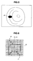
- Fig. 5 is a schematic view of an example of a generated edge image.
- Figs. 6 to 10 are enlarged views of an inappropriate region and a neighborhood.
- the image processing apparatus 1 extracts the inappropriate pixels in the inputted picked-up image (step S21).
- inappropriate pixels to be extracted include the R saturated pixel, halation pixel, and missing pixel.
- the extraction of the inappropriate pixels is performed by an extraction portion 2.
- Pixels of the two-dimensional picked-up image are sequentially scanned from, e.g., a pixel (1, 1), and a pixel in which a signal intensity value of any color signal is not less than a predetermined first threshold value or a pixel in which signal intensity values of all color signals are not more than a predetermined second threshold value is determined as an inappropriate pixel, thereby extracting the inappropriate pixels.
- the predetermined first threshold value is a signal intensity value of 255, and a pixel whose red signal intensity value is not less than 255 is the R saturated pixel or halation pixel and is determined as the inappropriate pixel.
- the predetermined second threshold value is a signal intensity value of 0, and a pixel in which signal intensity values of all color signals are not more than 0 is a missing pixel and is determined as an inappropriate pixel.
- the first threshold value and second threshold value are not limited to the above-described values and can be freely changed depending on an inappropriate pixel desired to be extracted.
- the image processing apparatus 1 labels the extracted inappropriate pixels (step S22).
- the labeling is performed by the extraction portion 2.
- the labeling is a process of sequentially scanning the pixels of the two-dimensional picked-up image from, e.g., the pixel (1, 1) and attaching a same attribute such as a number, i.e., a same label to adjacent inappropriate pixels.
- a label to be attached has a value different for each region composed of a plurality of inappropriate pixels. Further processing is performed for each of the labeled regions.
- the region composed of a plurality of inappropriate pixels will be referred to as an inappropriate region hereinafter.
- the image processing apparatus 1 performs edge detection and thinning on the color signals constituting the inputted picked-up image and generates an edge image (step S23).
- the edge detection and thinning is performed by a calculation portion 3.
- Step S23 constitutes edge image generation means.
- an edge image which is a binary image obtained by setting the pixels as detected edge portions to have a signal value of "1" and the other pixels to have a signal value of "0" is generated.
- the calculation portion 3 performs thinning, which is a process of altering an edge of a generated edge image to a continuous thin line having, e.g., a one-pixel width.
- thinning is a process of altering an edge of a generated edge image to a continuous thin line having, e.g., a one-pixel width.
- a method used for the edge detection and thinning processing may be any method.
- Fig. 5 shows an example of the generated edge image. As shown in Fig. 5 , an inner wall of a lumen in an inputted picked-up image is detected as the edges. The edge image includes an inappropriate region 20.
- the image processing apparatus 1 extracts a first boundary position at which the edge is tangent to an inappropriate region (step S24).
- the extraction of the first boundary position is performed by the calculation portion 3.
- Step S24 constitutes first boundary position extraction means.
- a first boundary position is a position of a pixel at which a certain edge is tangent to an inappropriate region.
- Fig. 6 shows an enlarged view of the inappropriate region 20 and a neighborhood. In Fig. 6 , one square corresponds to one pixel. A shaded pixel has a signal of "1" and represents the edge while a plain pixel is a pixel having a signal of "0". A pixel portion surrounded by a thick line indicates the inappropriate region 20.
- an edge 10 and an edge 11 are tangent to the inappropriate region 20.
- a position of a pixel (x1, y1) at which the edge 10 is tangent to the inappropriate region 20 is the first boundary position.
- the image processing apparatus 1 extracts an edge direction (step S25).
- the extraction of the edge direction is performed by the calculation portion 3.
- Step S25 constitutes edge direction extraction means.
- a pixel which is tangent to the pixel at the first boundary position and is not tangent to the inappropriate region is detected.
- the edge direction is calculated by (x1-x2, y1-y2).
- the edge direction is indicated by an arrow AR in Fig. 7 .
- Step S26 After the edge direction is extracted, the image processing apparatus 1 calculates a provisional reaching position based on the first boundary position and edge direction (step S26). The calculation of the provisional reaching position is performed by the calculation portion 3. Step S26 constitutes provisional reaching position calculation means.
- the provisional reaching position is a position where the edge first reaches after the edge is extended along the edge direction from the first boundary position into the inappropriate region 20 and crosses over the inappropriate region 20.
- Fig. 8 shows the provisional reaching position. As shown in Fig. 8 , a position (x3, y3) where the edge 10 first reaches after the edge 10 is extended in a direction of the arrow AR serving as the edge direction from the first boundary position (x1, y1) and crosses over the inappropriate region 20 is the provisional reaching position.
- Step S27 the image processing apparatus 1 extracts a second boundary position based on the provisional reaching position.
- the extraction of the second boundary position is performed by the calculation portion 3.
- Step S27 constitutes second boundary position extraction means.
- the calculation portion 3 first detects whether or not there is a pixel constituting an edge other than the edge 10 within a range of, e.g., 3 ⁇ 3 pixels about the provisional reaching position, i.e., the edge 11. Note that the range for detection of the edge 11 is not limited to the range of 3 ⁇ 3 pixels and can be freely changed.
- the calculation portion 3 determines that the edge 10 and edge 11 should be one continuous edge.
- the calculation portion 3 extracts a position of a pixel at which the edge 11 is tangent to the inappropriate region 20 as the second boundary position.
- Fig. 9 shows the second boundary position.
- the calculation portion 3 determines that the edge 10 and edge 11 are not continuous with each other and that there is no edge in the inappropriate region 20.
- the calculation portion 3 determines that there is no edge in the inappropriate region 20 and performs processing on a next labeled inappropriate region.
- the image processing apparatus 1 performs linear interpolation processing on a path between the first boundary position and the second boundary position and calculates a new signal value of each pixel in the path (step S28).
- the linear interpolation processing is performed by the calculation portion 3.
- Step S28 constitutes replacing information calculation means.
- the linear interpolation processing is a process of weighting a signal value of each of, e.g., four pixels around a pixel to be processed according to a distance from the pixel to be processed and calculating a new signal value as replacing information.
- the new signal values are calculated such that as much of a path obtained when the provisional reaching pixel is calculated in step S26 as possible is included, and a distance between the first boundary pixel and the second boundary pixel is shortest.
- the image processing apparatus 1 generates a replaced image obtained by replacing pixel information of each pixel in the inappropriate region with a corresponding calculated new signal value (step S29).
- the generation of the replaced image is performed by the replacement portion.
- Step S29 constitutes replaced image generation means.
- Fig. 10 shows an enlarged view of the inappropriate region 20 and neighborhood in the generated replaced image.
- the new signal values calculated by the linear interpolation processing constitute an edge 12 in the path between the first boundary position (x1, y1) and the second boundary position (x4, y4).
- the edge 12 connects the edge 10 and the edge 11.
- Step S30 the image processing apparatus 1 generates a three-dimensional image based on the replaced image.
- the processing is performed by the three-dimensional image generation portion 5.
- Step S30 constitutes three-dimensional image generation means.
- steps S23 to S29 are performed for the respective color signals.
- steps S21 and S22 constitute a pixel extraction step. Also note that steps S23 to S28 constitute a replacing pixel information calculation step. Step S29 constitutes a replaced image output step.
- the image processing apparatus 1 of the present embodiment is capable of calculating and replenishing image data of a portion from which an accurate image processing result is not obtained and outputting a three-dimensional image. That is, the image processing apparatus 1 is capable of altering the R saturated pixel, the halation pixel, and the missing pixel included in the input image to pixels suitable for three-dimensional image generation processing and generating a three-dimensional image based on the altered image.
- three-dimensional image generation processing may first be performed, and the pixel extraction step, the replacing pixel information calculation step, and the replaced image output step may then be performed.
- a signal value of each pixel is calculated using, e.g., a known polynomial operation method as disclosed in the specification of U.S. Patent Application Publication No. 2005/0001832 , and replacement with the signal value is performed.
- a picked-up image inputted to the image processing apparatus 1 in each of the first and second embodiments is an endoscope image picked up by the endoscope apparatus 6 as described above.
- methods for finding a lesioned part such as polyp from such endoscope images by image processing have been used. Since the image processing apparatus 1 of each of the above-described embodiments is capable of generating a replaced image obtained by replacing inappropriate pixels, the image processing apparatus 1 is effective in performing image processing for finding such a lesioned part.
- Fig. 11 is a flow chart showing a flow of a modification example of the image processing according to the embodiments of the present invention. A process to be described below starts when a picked-up image is inputted to the image processing apparatus 1.
- the image processing apparatus 1 extracts inappropriate pixels (step S31).
- inappropriate pixels included in the inputted picked-up image are extracted, as in the first and second embodiments described above.
- the image processing apparatus 1 sets an NG flag for each of the extracted inappropriate pixels (step S32). For example, an NG flag is set to "1" for each inappropriate pixel such that the pixel is excluded from the three-dimensional image generation processing performed in the three-dimensional image generation portion 5.
- the processing makes it possible to eliminate an influence of an inappropriate pixel in the three-dimensional image generation processing in the three-dimensional image generation portion 5.
- the image processing apparatus 1 is capable of calculating and replenishing image data of a part from which an accurate image processing result is not obtained. That is, the image processing apparatus 1 is capable of altering the R saturated pixel, the halation pixel, the missing pixel, and the like included in the input image to pixels suitable for the three-dimensional image generation processing.
- the input image may be determined to possess low reliability, and the input image may not be subjected to processing.
- the three-dimensional image generation portion 5 of the image processing apparatus 1 may perform a different image processing. Furthermore, the three-dimensional image generation portion 5 may be provided outside the image processing apparatus 1. That is, since the image processing apparatus 1 is capable of altering an input image including an inappropriate pixel to an image suitable for image processing, the image processing apparatus 1 can be applied to any image processing.
- image processing apparatus 1 of each of the embodiments of the present invention is an apparatus different from the endoscope apparatus 6, the image processing apparatus 1 may be provided inside the endoscope apparatus 6.
- the extraction portion 2, the calculation portion 3, the replacement portion 4, and the three-dimensional image generation portion 5 in each embodiment of the present invention have different configurations, one image processing portion or the like may perform the above-described processing.
- a picked-up image inputted to the image processing apparatus 1 is picked up by the endoscope apparatus 6.
- a picked-up image obtained using different image pickup means may be adopted.
Landscapes
- Engineering & Computer Science (AREA)
- Physics & Mathematics (AREA)
- Theoretical Computer Science (AREA)
- General Physics & Mathematics (AREA)
- Health & Medical Sciences (AREA)
- Life Sciences & Earth Sciences (AREA)
- Surgery (AREA)
- Computer Vision & Pattern Recognition (AREA)
- Radiology & Medical Imaging (AREA)
- Veterinary Medicine (AREA)
- Biomedical Technology (AREA)
- Heart & Thoracic Surgery (AREA)
- Medical Informatics (AREA)
- Molecular Biology (AREA)
- Animal Behavior & Ethology (AREA)
- General Health & Medical Sciences (AREA)
- Public Health (AREA)
- Pathology (AREA)
- Multimedia (AREA)
- Signal Processing (AREA)
- Optics & Photonics (AREA)
- Nuclear Medicine, Radiotherapy & Molecular Imaging (AREA)
- Biophysics (AREA)
- Image Processing (AREA)
- Endoscopes (AREA)
- Image Analysis (AREA)
- Facsimile Image Signal Circuits (AREA)
- Color Image Communication Systems (AREA)
Applications Claiming Priority (2)
| Application Number | Priority Date | Filing Date | Title |
|---|---|---|---|
| JP2006071197A JP4823725B2 (ja) | 2006-03-15 | 2006-03-15 | 医療用画像処理装置 |
| PCT/JP2007/053586 WO2007108280A1 (ja) | 2006-03-15 | 2007-02-27 | 医療用画像処理装置及び医療用画像処理方法 |
Publications (3)
| Publication Number | Publication Date |
|---|---|
| EP1994877A1 true EP1994877A1 (de) | 2008-11-26 |
| EP1994877A4 EP1994877A4 (de) | 2010-08-25 |
| EP1994877B1 EP1994877B1 (de) | 2013-04-03 |
Family
ID=38522316
Family Applications (1)
| Application Number | Title | Priority Date | Filing Date |
|---|---|---|---|
| EP07714979A Not-in-force EP1994877B1 (de) | 2006-03-15 | 2007-02-27 | Medizinische bildverarbeitungsvorrichtung und medizinisches bildverarbeitungsverfahren |
Country Status (5)
| Country | Link |
|---|---|
| US (1) | US8335361B2 (de) |
| EP (1) | EP1994877B1 (de) |
| JP (1) | JP4823725B2 (de) |
| CN (1) | CN101389261B (de) |
| WO (1) | WO2007108280A1 (de) |
Families Citing this family (10)
| Publication number | Priority date | Publication date | Assignee | Title |
|---|---|---|---|---|
| JP5086830B2 (ja) * | 2008-02-08 | 2012-11-28 | 株式会社キーエンス | 画像検査装置、画像検査方法、及びコンピュータプログラム |
| JP4792117B2 (ja) | 2010-03-15 | 2011-10-12 | 株式会社東芝 | 文書画像処理装置、文書画像処理方法および文書画像処理プログラム |
| JP5658931B2 (ja) * | 2010-07-05 | 2015-01-28 | オリンパス株式会社 | 画像処理装置、画像処理方法、および画像処理プログラム |
| JP6112879B2 (ja) * | 2013-01-28 | 2017-04-12 | オリンパス株式会社 | 画像処理装置、内視鏡装置、画像処理装置の作動方法及び画像処理プログラム |
| JP2016158682A (ja) * | 2015-02-27 | 2016-09-05 | Hoya株式会社 | 画像処理装置 |
| JP6346576B2 (ja) | 2015-02-27 | 2018-06-20 | Hoya株式会社 | 画像処理装置 |
| JP6531202B2 (ja) * | 2018-05-25 | 2019-06-12 | Hoya株式会社 | 画像処理装置 |
| US11288863B2 (en) * | 2018-12-04 | 2022-03-29 | Intuitive Research And Technology Corporation | Voxel build |
| US11941759B2 (en) * | 2018-12-04 | 2024-03-26 | Intuitive Research And Technology Corporation | Voxel build |
| US12189722B2 (en) | 2021-10-19 | 2025-01-07 | International Business Machines Corporation | Content based on-device image adjustment |
Family Cites Families (15)
| Publication number | Priority date | Publication date | Assignee | Title |
|---|---|---|---|---|
| US183205A (en) | 1876-10-10 | Improvement in sphygmographs | ||
| JP2712495B2 (ja) * | 1989-02-28 | 1998-02-10 | 株式会社島津製作所 | X線透視画像の欠陥補償装置 |
| US5079698A (en) * | 1989-05-03 | 1992-01-07 | Advanced Light Imaging Technologies Ltd. | Transillumination method apparatus for the diagnosis of breast tumors and other breast lesions by normalization of an electronic image of the breast |
| JP3078085B2 (ja) | 1991-03-26 | 2000-08-21 | オリンパス光学工業株式会社 | 画像処理装置および画像処理方法 |
| JPH0829701A (ja) * | 1994-07-18 | 1996-02-02 | Olympus Optical Co Ltd | 立体視内視鏡システム |
| JP3689212B2 (ja) | 1997-01-17 | 2005-08-31 | オリンパス株式会社 | 画像処理装置 |
| JP3719010B2 (ja) | 1998-09-04 | 2005-11-24 | コニカミノルタホールディングス株式会社 | 放射線画像処理方法および放射線画像処理装置 |
| JP3700419B2 (ja) * | 1998-10-22 | 2005-09-28 | コニカミノルタホールディングス株式会社 | 放射線画像処理装置 |
| US6529618B1 (en) | 1998-09-04 | 2003-03-04 | Konica Corporation | Radiation image processing apparatus |
| JP4885388B2 (ja) * | 2001-09-25 | 2012-02-29 | オリンパス株式会社 | 内視鏡挿入方向検出方法 |
| US7181086B2 (en) | 2002-06-06 | 2007-02-20 | Eastman Kodak Company | Multiresolution method of spatially filtering a digital image |
| KR100506085B1 (ko) * | 2002-12-28 | 2005-08-05 | 삼성전자주식회사 | 혀영상 처리장치 및 혀영상을 이용한 건강 모니터링장치 |
| US7480401B2 (en) | 2003-06-23 | 2009-01-20 | Siemens Medical Solutions Usa, Inc. | Method for local surface smoothing with application to chest wall nodule segmentation in lung CT data |
| DE102004008979B4 (de) * | 2004-02-24 | 2006-12-28 | Siemens Ag | Verfahren zur Filterung tomographischer 3D-Darstellungen nach erfolgter Rekonstruktion von Volumendaten |
| JP5131951B2 (ja) * | 2006-02-21 | 2013-01-30 | 富士フイルム株式会社 | 体腔内観察装置 |
-
2006
- 2006-03-15 JP JP2006071197A patent/JP4823725B2/ja not_active Expired - Fee Related
-
2007
- 2007-02-27 EP EP07714979A patent/EP1994877B1/de not_active Not-in-force
- 2007-02-27 CN CN2007800069166A patent/CN101389261B/zh not_active Expired - Fee Related
- 2007-02-27 WO PCT/JP2007/053586 patent/WO2007108280A1/ja not_active Ceased
-
2008
- 2008-09-12 US US12/209,567 patent/US8335361B2/en active Active
Also Published As
| Publication number | Publication date |
|---|---|
| WO2007108280A1 (ja) | 2007-09-27 |
| CN101389261A (zh) | 2009-03-18 |
| US8335361B2 (en) | 2012-12-18 |
| US20090074271A1 (en) | 2009-03-19 |
| EP1994877B1 (de) | 2013-04-03 |
| CN101389261B (zh) | 2010-10-13 |
| JP2007244589A (ja) | 2007-09-27 |
| JP4823725B2 (ja) | 2011-11-24 |
| EP1994877A4 (de) | 2010-08-25 |
Similar Documents
| Publication | Publication Date | Title |
|---|---|---|
| EP1994877B1 (de) | Medizinische bildverarbeitungsvorrichtung und medizinisches bildverarbeitungsverfahren | |
| EP1994878B9 (de) | Vorrichtung und verfahren zur bearbeitung medizinischer bilder | |
| EP2008571B1 (de) | Vorrichtung zum nachweis der einführrichtung eines endoskops und verfahren zum nachweis der einführrichtung eines endoskops | |
| US8515141B2 (en) | Medical image processing apparatus and method for detecting locally protruding lesion | |
| US8711252B2 (en) | Image processing device and information storage medium including motion vector information calculation | |
| JP5276225B2 (ja) | 医用画像処理装置及び医用画像処理装置の作動方法 | |
| US20100092055A1 (en) | Image processing apparatus, image processing program product, and image processing method | |
| JP4902735B2 (ja) | 医療用画像処理装置及び医療用画像処理方法 | |
| CN106102556B (zh) | 图像处理装置 | |
| EP1849402B1 (de) | Medizinische bildverarbeitungsvorrichtung, lumenbildverarbeitungsvorrichtung, lumenbildverarbeitungsverfahren und programme für sie | |
| EP2305091A1 (de) | Bildgebungsgerät, bildgebungsprogramm und bildverarbeitungsverfahren | |
| JP2010187756A (ja) | 画像処理装置、画像処理方法および画像処理プログラム | |
| US8666135B2 (en) | Image processing apparatus | |
| JPWO2012153568A1 (ja) | 医用画像処理装置 | |
| CN113744266A (zh) | 一种病灶检测框的显示方法、装置、电子设备及存储介质 | |
| JP4855673B2 (ja) | 医用画像処理装置 | |
| EP1992273B1 (de) | Medizinische bildverarbeitungsvorrichtung und medizinisches bildverarbeitungsverfahren | |
| US20260073661A1 (en) | Image processing apparatus and image processing method | |
| US12347070B2 (en) | Processor for electronic endoscope and electronic endoscopic system | |
| JP2009017037A (ja) | 画像処理装置 | |
| CN120599318A (zh) | 医疗图像处理装置、分层型神经网络、医疗图像处理方法及程序产品 | |
| JPWO2016056408A1 (ja) | 画像処理装置、画像処理方法、及び画像処理プログラム | |
| JP4856275B2 (ja) | 医用画像処理装置 | |
| CN121961964A (zh) | 内窥镜图像的增强方法、装置、电子设备及存储介质 | |
| JP2014171535A (ja) | 画像処理装置 |
Legal Events
| Date | Code | Title | Description |
|---|---|---|---|
| PUAI | Public reference made under article 153(3) epc to a published international application that has entered the european phase |
Free format text: ORIGINAL CODE: 0009012 |
|
| 17P | Request for examination filed |
Effective date: 20080912 |
|
| AK | Designated contracting states |
Kind code of ref document: A1 Designated state(s): DE FR GB |
|
| RBV | Designated contracting states (corrected) |
Designated state(s): DE FR GB |
|
| DAX | Request for extension of the european patent (deleted) | ||
| RBV | Designated contracting states (corrected) |
Designated state(s): DE FR GB |
|
| A4 | Supplementary search report drawn up and despatched |
Effective date: 20100722 |
|
| 17Q | First examination report despatched |
Effective date: 20111124 |
|
| GRAP | Despatch of communication of intention to grant a patent |
Free format text: ORIGINAL CODE: EPIDOSNIGR1 |
|
| RIN1 | Information on inventor provided before grant (corrected) |
Inventor name: SAWA, MIHO Inventor name: NAKAMURA, KENJI Inventor name: TANAKA, HIDEKI Inventor name: INOUE, RYOKO Inventor name: NISHIMURA, HIROKAZU |
|
| GRAS | Grant fee paid |
Free format text: ORIGINAL CODE: EPIDOSNIGR3 |
|
| GRAA | (expected) grant |
Free format text: ORIGINAL CODE: 0009210 |
|
| AK | Designated contracting states |
Kind code of ref document: B1 Designated state(s): DE FR GB |
|
| REG | Reference to a national code |
Ref country code: GB Ref legal event code: FG4D |
|
| REG | Reference to a national code |
Ref country code: DE Ref legal event code: R096 Ref document number: 602007029463 Country of ref document: DE Effective date: 20130529 |
|
| PLBE | No opposition filed within time limit |
Free format text: ORIGINAL CODE: 0009261 |
|
| STAA | Information on the status of an ep patent application or granted ep patent |
Free format text: STATUS: NO OPPOSITION FILED WITHIN TIME LIMIT |
|
| 26N | No opposition filed |
Effective date: 20140106 |
|
| REG | Reference to a national code |
Ref country code: DE Ref legal event code: R097 Ref document number: 602007029463 Country of ref document: DE Effective date: 20140106 |
|
| GBPC | Gb: european patent ceased through non-payment of renewal fee |
Effective date: 20140227 |
|
| REG | Reference to a national code |
Ref country code: FR Ref legal event code: ST Effective date: 20141031 |
|
| PG25 | Lapsed in a contracting state [announced via postgrant information from national office to epo] |
Ref country code: FR Free format text: LAPSE BECAUSE OF NON-PAYMENT OF DUE FEES Effective date: 20140228 Ref country code: GB Free format text: LAPSE BECAUSE OF NON-PAYMENT OF DUE FEES Effective date: 20140227 |
|
| REG | Reference to a national code |
Ref country code: DE Ref legal event code: R082 Ref document number: 602007029463 Country of ref document: DE Representative=s name: WUESTHOFF & WUESTHOFF, PATENTANWAELTE PARTG MB, DE Ref country code: DE Ref legal event code: R081 Ref document number: 602007029463 Country of ref document: DE Owner name: OLYMPUS CORPORATION, JP Free format text: FORMER OWNER: OLYMPUS MEDICAL SYSTEMS CORP., TOKYO, JP |
|
| PGFP | Annual fee paid to national office [announced via postgrant information from national office to epo] |
Ref country code: DE Payment date: 20190219 Year of fee payment: 13 |
|
| REG | Reference to a national code |
Ref country code: DE Ref legal event code: R119 Ref document number: 602007029463 Country of ref document: DE |
|
| PG25 | Lapsed in a contracting state [announced via postgrant information from national office to epo] |
Ref country code: DE Free format text: LAPSE BECAUSE OF NON-PAYMENT OF DUE FEES Effective date: 20200901 |