EP1994880A1 - Bildanalysegerät - Google Patents
Bildanalysegerät Download PDFInfo
- Publication number
- EP1994880A1 EP1994880A1 EP07737789A EP07737789A EP1994880A1 EP 1994880 A1 EP1994880 A1 EP 1994880A1 EP 07737789 A EP07737789 A EP 07737789A EP 07737789 A EP07737789 A EP 07737789A EP 1994880 A1 EP1994880 A1 EP 1994880A1
- Authority
- EP
- European Patent Office
- Prior art keywords
- image
- processing means
- abnormal tissue
- intraluminal
- image analysis
- Prior art date
- Legal status (The legal status is an assumption and is not a legal conclusion. Google has not performed a legal analysis and makes no representation as to the accuracy of the status listed.)
- Withdrawn
Links
Images





Classifications
-
- G—PHYSICS
- G06—COMPUTING OR CALCULATING; COUNTING
- G06T—IMAGE DATA PROCESSING OR GENERATION, IN GENERAL
- G06T7/00—Image analysis
- G06T7/0002—Inspection of images, e.g. flaw detection
- G06T7/0012—Biomedical image inspection
-
- G—PHYSICS
- G06—COMPUTING OR CALCULATING; COUNTING
- G06T—IMAGE DATA PROCESSING OR GENERATION, IN GENERAL
- G06T7/00—Image analysis
- G06T7/70—Determining position or orientation of objects or cameras
- G06T7/73—Determining position or orientation of objects or cameras using feature-based methods
- G06T7/74—Determining position or orientation of objects or cameras using feature-based methods involving reference images or patches
-
- G—PHYSICS
- G06—COMPUTING OR CALCULATING; COUNTING
- G06V—IMAGE OR VIDEO RECOGNITION OR UNDERSTANDING
- G06V10/00—Arrangements for image or video recognition or understanding
- G06V10/40—Extraction of image or video features
- G06V10/44—Local feature extraction by analysis of parts of the pattern, e.g. by detecting edges, contours, loops, corners, strokes or intersections; Connectivity analysis, e.g. of connected components
- G06V10/443—Local feature extraction by analysis of parts of the pattern, e.g. by detecting edges, contours, loops, corners, strokes or intersections; Connectivity analysis, e.g. of connected components by matching or filtering
-
- G—PHYSICS
- G06—COMPUTING OR CALCULATING; COUNTING
- G06T—IMAGE DATA PROCESSING OR GENERATION, IN GENERAL
- G06T2207/00—Indexing scheme for image analysis or image enhancement
- G06T2207/10—Image acquisition modality
- G06T2207/10068—Endoscopic image
-
- G—PHYSICS
- G06—COMPUTING OR CALCULATING; COUNTING
- G06T—IMAGE DATA PROCESSING OR GENERATION, IN GENERAL
- G06T2207/00—Indexing scheme for image analysis or image enhancement
- G06T2207/30—Subject of image; Context of image processing
- G06T2207/30004—Biomedical image processing
- G06T2207/30028—Colon; Small intestine
Definitions
- the present invention relates to an image analysis device that detects a polyp from a medical image.
- an image pickup instrument such as X-ray, CT, MRI, ultrasound observation device, and endoscopic device.
- a diagnosis can be performed by inserting an elongated insertion section in a body cavity and using image pickup means such as a solid-state image pickup device to thereby observe intracavital organs on a monitor screen.
- image pickup means such as a solid-state image pickup device
- An ultrasound endoscopic device is also widely used that is capable of detecting or diagnosing by irradiating ultrasound to the intracavital organs and observing the conditions of the intracavital organs with a monitor screen based on the reflection or the transmittance of the ultrasound.
- diagnosis supporting device that supports the doctor's diagnosis by calculating a feature value related to an image to be picked up using an image analysis method and presenting objective and numerical diagnosis supporting information to the doctor.
- the feature value herein denotes a numerical value that reflects various findings on the image and can be obtained by applying the image analysis method.
- Non-Patent Document 1 Digestive Endoscopy", 2001 Vol.13 No.3 vol.13, Tokyo Igakusha P349-354 ) is an example of discrimination of lesion malignancy based on a mucous finding and a finding related to the shape of blood vessels.
- an image analysis method is disclosed that is capable of improving the lesion determination accuracy based on an objectified result of the findings using the feature value.
- Japanese Patent Application Laid-Open Publication No. 2005-157902 blood vessels in the digestive tract image are extracted as a linear pattern for use in the lesion determination in the image analysis method.
- An example of an object to be detected in a large intestine includes an elevated lesion (large intestine polyps).
- an elevated lesion large intestine polyps.
- the present invention has been made in view of the foregoing circumstances, and an object thereof is to provide an image analysis device capable of improving the detection of existing locations of large intestine polyps.
- One aspect of the image analysis device of the present invention comprises abnormal tissue existence determination processing means for determining whether an intraluminal abnormal tissue exists based on data of pixels or small areas of an intraluminal image.
- Figs. 1 to 13 are related to a first embodiment of the present invention.
- Fig. 1 is a configuration diagram showing a configuration of an endoscopic image analysis device.
- Fig. 2 is a diagram showing information stored in a memory of Fig. 1.
- Fig. 3 is a first diagram for describing an action of an image processing device of Fig. 1 .
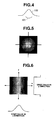
- Fig. 4 is a second diagram for describing an action of the image processing device of Fig. 1 .
- Fig. 5 is a third diagram for describing an action of the image processing device of Fig. 1 .
- Fig. 6 is a fourth diagram for describing an action of the image processing device of Fig. 1 .
- Fig. 1 is a configuration diagram showing a configuration of an endoscopic image analysis device.
- Fig. 2 is a diagram showing information stored in a memory of Fig. 1.
- Fig. 3 is a first diagram for describing an action of an image processing device of Fig. 1 .
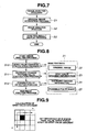
- FIG. 7 is a flow chart showing a flow of a process of an image analysis program executed by a CPU of Fig. 1 .
- Fig. 8 is a flow chart showing a flow of the image analysis process of Fig. 7.
- Fig. 9 is a first diagram for describing a gray value gradient calculation process of Fig. 8 .
- Fig. 10 is a second diagram for describing the gray value gradient calculation process of Fig. 8 .
- Fig. 11 is a flow chart showing a flow of an isotropic change feature value calculation process of Fig. 8 .
- Fig. 12 is a flow chart showing a flow of a possible polyp detection process of Fig. 8 .
- Fig. 13 is a diagram for describing a modified example of the image analysis process of Fig. 8 .
- an endoscopic image analysis device 1 of the present embodiment comprises an endoscopic observation device 2 that picks up an image inside a living body and that outputs an analog image signal, an endoscopic filing device 3 that generates image data from the analog image signal outputted from the endoscopic observation device 2 and that stores the generated image data, and an image processing device 4 that executes an image analysis process.
- the image processing device 4 comprises: an information processing device 5 that executes information processing; an operation device 6 including a keyboard, a mouse, and the like; a storage device 7 including a hard disk and the like; and a display device 8 including display means such as a CRT, a liquid crystal display, or a plasma display.
- the endoscopic filing device 3 and the information processing device 5 are connected, for example, to a LAN 9 with TCP/IP as the protocol, and are capable of mutual communication.
- a general personal computer is used as the information processing device 5, the computer acquiring the image data stored in the endoscope filing device 3 through the LAN 9, executing an image analysis process to the image data, and displaying an image analysis result on a display device 8. Designating the image data to be processed, instructing acquisition of the designated image data, and instructing execution of the process are executed by an operation using the operation device 6.
- a CPU 10 as abnormal tissue existence determination processing means that executes the control and process
- a memory 11 that stores processing program data
- an external storage I/F 12 that reads and writes information to and from the storage device 7
- a network card 13 that communicates with an external device
- an operation I/F 14 that executes input and output with the operation device 6
- a graphic board 15 that outputs a video signal on the display device 8 are connected to a bus 16 and communicate each other through the bus 16.
- the network card 13 executes a data transmission and reception process with the endoscope filing device 8 connected to the LAN 9.
- the operation I/F 14 receives an input signal inputted by the keyboard or the mouse of the operation device 6 and executes necessary data processing.
- the storage device 7 is connected to the information processing device 5 and stores an image analysis program 20 for executing an image analysis process.
- the image analysis program 20 comprises a plurality of executable files, dynamic link library files, or configuration files.
- the external storage I/F 12 reads out the image analysis program 20 stored in the storage device 7 and makes the memory 11 store the image analysis program 20.
- the memory 11 holds the image analysis program 20 and analysis data 21.
- the image analysis program 20 stored in the memory 11 is a program with which the CPU 10 acquires endoscopic image data designated by the operation device 6 from the endoscope filing device 3, executes an image analysis process to the acquired image data, and executes a display process of an image analysis result to the display device 8.
- the analysis data 21 stored in the memory 11 is data acquired and generated by the processes by the CPU 10.
- the stored analysis data 21 includes an original image 22 that is image data acquired from the endoscope filing device 3, gray value gradient information 23 generated by various processes described below, isotropic change information 24, and a possible polyp image 26.
- a large intestine polyp 100 is observed from an oblique direction using the endoscopic observation device 2, an edge 101 is observed as shown in Fig. 4 . Therefore, a candidate of the large intestine polyp 100 can be detected using an edge detection method of a conventional method. However, if the large intestine polyp is observed from above, the edge cannot be observed as shown in Fig. 5 . Thus, the candidate of the large intestine polyp 100 cannot be detected even if the edge detection method is used.
- the edge is not observed with an observation from above. Furthermore, when a virtual line is drawn in the image to observe a gray value change of pixels on the line, the large intestine polyp and the folds exhibit the same changed shape depending on how the line is drawn (for example, gray value change in the y-direction of Fig. 6 ). Therefore, when a detection of a large intestine polyp is attempted based on a one-dimensional gray value change (for example, gray value change in the x-direction of Fig. 6 ), the folds may be erroneously detected at the same time.
- the CPU 10 acquires image data designated by the operation of the operation device 6 from the endoscope filing device 3 and stores the image data in the memory 11 as the original image 22 in step S1 of an original image acquisition process as shown in Fig. 7 .
- step S2 of an image analysis process the CPU 10 processes the original image 22 acquired in the original image acquisition process step S 1 to generate the gray value gradient information 23, isotropic change information 24, and the possible polyp image 26 and store the generated pieces of information in the memory 11.
- step S3 of an analysis result display process the CPU 10 executes a process of displaying an analysis process image on the display device 8, in which the possible polyp image 26 is superimposed on the original image 22.
- step S10 the CPU 10 executes a gray value gradient calculation process described below to, for example, an R signal. Subsequently, the CPU 10 executes an isotropic change feature value calculation process described below based on a gray value gradient calculated in step S 11. The CPU 10 further executes a possible polyp detection process for generating the possible polyp image 26 at a location where the polyp exists based on an isotropic change feature value calculated in step S12.
- step S10 The gray value gradient calculation process of step S10 will be described first. As shown in Fig. 9 , the gray value gradient calculation process obtains for each pixel, for example, a gray value gradient in relation to the R signal of the original image for each of 3 by 3 pixels around the target point.
- differences of R pixel signals three pixels apart in the x and y directions are extracted.
- a difference average value of an x direction component (0° direction) of the gray value gradient is defined as gx
- a difference average value of a y direction component is defined as gy
- a difference average value in the reverse direction of gx 180° direction
- a difference average value in the reverse direction of gy 270° direction
- Character AVE denotes a function for returning an average value of numerical values related to i
- Gray value gradient information of the foregoing four directions and pixel values of the target point are recorded in the memory 11 as gray value gradient information.
- the isotropic change feature value calculation process of step S 11 will be described next. As shown in Fig. 11 , the isotropic change feature value calculation process acquires the gray value gradient information calculated pixel by pixel in the gray value gradient calculation process in step S20 and obtains difference values of the gray value gradient information in step S21.
- step S22 a pixel value R (R22 in Fig. 10 ) indicated by the target point and a predetermined threshold Rt are compared. If R>Rt, the three difference values are recorded in the memory 11 as isotropic change information in step S23, and the process ends.
- step S 12 The possible polyp detection process of step S 12 will now be described. As shown in Fig. 12 , the possible polyp detection process first acquires isotropic change information calculated pixel by pixel in an isotropic change feature value calculation process in step S30.
- step S32 a predetermined threshold Dt is used to determine whether dxy ⁇ Dt, dxxy ⁇ Dt, and dyxy ⁇ Dt. If the condition is satisfied, a pixel value of the location of the possible polyp image is updated to "1" in step S33. If the condition is not satisfied, the pixel value of the location is updated to "0" in step S34.
- step S34 the possible polyp image 26, in which the pixel value of the location where the polyp exists is "1", is generated, and the process ends.
- a marker is displayed at the location where the pixel value of the possible polyp image 26 is "1", thereby superimposing on the display of the original image 22.
- the processes are executed to, for example, the R signal of the original image 22.
- this arrangement is not restrictive, and the processes may be executed to a G signal or a B signal.
- a two-dimensional gray value change is inspected to detect polyp without an edge from the image and present the polyp as a possible lesion, thereby enabling to present the existing location of the polyp to the doctor (operator) and support the lesion detection.
- the gray value gradient information is obtained from the differences from the pixel values three pixels apart.
- a configurable parameter variable N may be set up to obtain the differences N pixels apart, enabling to adjust the scale of the gray value gradient information.
- an element structure tensor T 1 related to the gray value gradient of each pixel is obtained from the following formulas (1) and (2).
- Formula 1 ⁇ I ⁇ gx , gy ⁇ Formula 2
- T l ⁇ I ⁇ I T
- the pixel value R indicated as the target point and the predetermined threshold Rt are compared, and if R>Rt, the feature value u is recorded in the memory 11 as the isotropic change information (equivalent to step S23 of Fig. 11 ).
- a predetermined threshold Ut is then used to determine whether u>Ut (equivalent to step S32 of Fig. 12 ). If the condition is satisfied, the pixel value of the location of the possible polyp image is updated to "1" (equivalent to step S33 of Fig. 12 ). If the condition is not satisfied, the pixel value of the location is updated to "0" (equivalent to step S34 of Fig. 12 ).
- Figs. 14 to 20 are related to a second embodiment of the present invention.
- Fig. 14 is a diagram showing information stored in a memory.
- Fig. 15 is a flow chart showing a flow of an image analysis process in an image analysis program of Fig. 14 .
- Fig. 16 is a flow chart showing a flow of a possible polyp detection process of Fig. 15 .
- Fig. 17 is a diagram for describing the possible polyp detection process of Fig. 16 .
- Fig. 18 is a first diagram for describing a modified example of a detection method of quasi-circular shape in the possible polyp detection process of Fig. 16 .
- Fig. 15 is a flow chart showing a flow of an image analysis process in an image analysis program of Fig. 14 .
- Fig. 16 is a flow chart showing a flow of a possible polyp detection process of Fig. 15 .
- Fig. 17 is a diagram for describing the possible polyp detection process of Fig. 16
- FIG. 19 is a second diagram for describing a modified example of the detection method of quasi-circular shape in the possible polyp detection process of Fig. 16 .
- Fig. 20 is a third diagram for describing a modified example of the detection method of quasi-circular shape of the possible polyp detection process of Fig. 16 .
- the second embodiment is almost the same as the first embodiment. Therefore, only the different points will be described, and the same configurations are designated with the same reference numerals and the description will be omitted.
- the analysis data 21 stored in the memory 11 comprises: an original image 22, which is image data acquired from the endoscope filing device 3; a binarized image 30 generated by various processes described below; a labeling image 31; a thinned image 32; and a possible polyp image 26.
- an original image 22 which is image data acquired from the endoscope filing device 3
- a binarized image 30 generated by various processes described below
- a labeling image 31 a thinned image 32
- a possible polyp image 26 The rest of the configuration is the same as that of the first embodiment.
- Fig. 15 The image analysis process of the image analysis program 20 of the present embodiment executed by the CPU 10 will be described using Fig. 15 .
- the CPU 10 uses the image analysis program 20 to execute an edge extraction process with a known Sobel filter to, for example, an R signal of the original image 22.
- a pixel value obtained as a processing result is equal to or greater than the predetermined threshold Rt, the CPU 10 generates the binarized image 30 in which the pixel is "1".
- the edge extraction process is executed to, for example, the R signal of the original image 22.
- this arrangement is not restrictive, and the process may be executed to a G signal or a B signal of the original image 22.
- step S41 the CPU 10 generates the labeling image 31 in which a label is allocated to each of connected components of the pixels whose pixel values of the binarized image 30 are "1".
- the CPU 10 In a thinning processing step of step S42, the CPU 10 generates the thinned image 32 in which each label value in the labeling image 31 is thinned by, for example, a known Hildich method.
- the thinned image 32 is an image in which an edge included in the original image 22 is extracted as an edge line formed of connected components of one pixel and a label is allocated to each connected component.
- Each edge includes a visible outline of an elevated possible lesion of large intestine and a visible outline of a structure other than the lesion.
- the generation method of the labeling image 31 and the thinned image 32 is already known as disclosed in, for example, Japanese Patent Application Laid-Open Publication No. 2005-157902 . Therefore, the description will be omitted.
- the possible polyp detection process of the present embodiment is a process in which only an edge line that is highly likely an elevated lesion is extracted from the edge lines of the thinned image 32 to generate the possible polyp image 26.
- Fig. 16 is a diagram showing a process flow chart in the possible polyp detection process of the present embodiment.
- the CPU 10 acquires edge line information having a label value "1" in step S50.
- step S51 the CPU 10 executes a Hough transform related to quasi-circular shape and extracts circles constituting the edge line.
- Fig. 17 shows an extraction example. The example of Fig. 17 illustrates that four circles A, B, C, and D are extracted as circle elements constituting the edge line.
- step S52 the CPU 10 uses a threshold to determine a degree of coincidence of a circle with the highest coincidence with the edge line among the extracted circles. Whether the ratio between the number of pixels of the edge line of step S50 and the number of coincided pixels is greater than a predetermined value R0 is determined.
- the circle that overlaps with most pixels constituting the edge line is a circle A, and the ratio of the number of pixels of the edge line and the number of coincided pixels is greater than R0. Therefore, the circle A is detected. If no radius of pertinent circle exists, the circle is removed from the possible large intestine polyps.
- step S53 the CPU 10 compares a radius r of the circle determined in step S52 and predetermined thresholds rmin and rmax. If rmin ⁇ r ⁇ rmax, it is determined that the pertinent edge line indicates a visible outline of polyp, and the possible polyp image 26, in which the pixel of the edge line is "1", is generated in step S54.
- the CPU 10 executes the foregoing steps to each label value of the thinned image 32 and superimposes the processing results to the possible polyp image 26, thereby generating a possible polyp labeling image in which the possible polyp edge is labeled.
- the present embodiment superimposes the possible polyp labeling image on the original image 22 for display on the display device 8, thereby enabling to easily check the possible polyp location on the image which is the existing location of polyp.
- the present embodiment may be configured to calculate a complex PARCOR coefficient based on a series of points on the edge line, discriminate and analyze the coefficient with the classification shown in Figs. 18 to 20 as the right answer, and then detect the quasi-circular shape.
- Figs. 21 to 29 are related to a third embodiment of the present invention.
- Fig. 21 is a first diagram for describing a pretreatment of an edge extraction process.
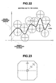
- Fig. 22 is a second diagram for describing the pretreatment of Fig. 21 .
- Fig. 23 is a third diagram for describing the pretreatment of Fig. 21 .
- Fig. 24 is a fourth diagram for describing the pretreatment of Fig. 21 .
- Fig. 25 is a fifth diagram for describing the pretreatment of Fig. 21 .
- Fig. 26 is a first flow chart showing a flow of the pretreatment of Fig. 21 .
- Fig. 27 is a first diagram for describing a process of Fig. 26.
- Fig. 28 is a second diagram for describing the process of Fig. 26 .
- Fig. 29 is a second flow chart showing a flow of the pretreatment of Fig. 21 .
- the third embodiment is almost the same as the second embodiment. Therefore, only the different points will be described, and the same configurations are designated with the same reference numerals and the description will be omitted.
- An example of an object to be detected in a large intestine includes an elevated lesion (large intestine polyps).
- One method of the conventional techniques includes a method for detecting the maximum of the gray value of an image and determining the location as a possible large intestine polyp. In that case, if the maximum is steep, the maximum does not indicate a large intestine polyp, but is noise caused by content such as a minute residue. Therefore, a morphology filter is used for noise removal.
- the CPU 10 executes an appropriate process to an image with a distortion aberration to improve the detection accuracy of large intestine polyps.
- the CPU 10 removes noise from the original image 22 caused by content, such as a residue, as a pretreatment of the edge extraction process in step S40 of Fig. 15 in the second embodiment.
- the morphology filter is generally used as a method for the noise removal.
- a steep peak as shown in Fig. 21 exists, "erosion”, one of the morphology filter processes, is executed, and then "dilation”, one of the morphology filter processes, is executed to remove the steep peak.
- Fig. 21 shows an example in which "erosion” is executed.
- Fig. 22 in the morphology filter, "dilation” includes a figure expansion action, and “erosion” includes a figure contraction action. Therefore, the morphology filter outputs a trajectory of the centers of spheres or ellipsoids when crawled to contact with data values targeting the spheres and the ellipsoids.
- the morphology filter is crawled above the data values in “dilation” and crawled below the data values in “erosion”.
- the peaks less than the sizes of the spheres or the ellipsoids can be removed with “erosion” and “dilation”.
- the endoscopic image includes a distortion aberration so that the scales at the center of image and on the periphery are different. Therefore, as shown in Fig. 23 , the actual sizes in the endoscopic image differ depending on the distance and direction from the center of the image.
- the CPU 10 prepares functions f(1) and g(1) for outputting long axis/short axis of an ellipsoid in accordance with a distance 1 from the centers of both sides based on a difference specification of lens or an actual measurement value. These functions are constituted by lookup tables or formulas.
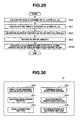
- Fig. 26 shows a process flow chart when applying "dilation" of the morphology filter to an image I in the present embodiment (similar process is also executed with “erosion”).
- Fig. 26 illustrates a process related to a pixel (x, y). The process is applied to the entire image I to obtain a "dilation" processed image.
- the CPU 10 reserves an image buffer having the same size as the image I in the memory 11 and stores a "dilation” processing result in the image buffer.
- a pixel value of the image I is copied and stored prior to the "dilation" process.
- the CPU 10 obtains an angle ⁇ formed by a targeted pixel (x, y) and a center pixel (cx, cy) of the image I in step S60 (see, Fig. 27 ).
- step S61 the CPU 10 obtains a distance L between the targeted pixel (x, y) and the center pixel (cx, cy) of the image I.
- step S62 the CPU 10 uses the functions f(1), g(1), and the distance L obtained in step S61 to obtain an ellipsoid whose long axis is f(L) and short axis is g(L) as shown in Fig. 28 .
- step S63 the CPU 10 rotates the ellipsoid obtained in step S62 by the angle ⁇ obtained in step S60.
- step S64 the CPU 10 executes the "dilation" process in the pixel (x, y).
- the processing result is stored in the image buffer having the same size as the image I. If the pixel value in an area occupied by the filter in the image buffer is larger than the pixel value of the filter processing result, the pixel value is replaced by the pixel value of the filter processing result.
- Fig. 29 shows a flow chart of the "erosion” process.
- the “erosion” process is almost the same as the “dilation” process, and the only difference is that the “erosion” process in the pixel (x, y) is executed in step S64a in place of step S64. Therefore, the description will be omitted.
- the CPU 10 may also generate a template to execute a template matching process, and the matching accuracy can be improved by executing the process while correcting the template in consideration of the distortion aberration of the image in the template matching process.
- endoscopic image data in a large intestine has been used as an example of the image data
- a large intestine polyp has been described as an example of the intraluminal abnormal tissue.
- this arrangement is not restrictive, and other intraluminal image data can also be applied to detect other intraluminal abnormal tissues.
- a gray value gradient calculation section 200 as gray value gradient calculation means for executing the gray value gradient calculation process (for example, step S10 of Fig. 8 ), an isotropy evaluation section 201 as isotropy evaluation processing means for executing the isotropic change feature value calculation process (for example, step S 11 of Fig. 8 ), an edge extraction section 202 as edge extraction processing means for executing the edge extraction process (for example, step S40 of Fig. 15 ), a possible polyp detection section 203 as possible abnormal tissue detection processing means for executing the possible polyp detection process (for example, step S12 of Fig.
- a filter/template generating section 204 as filter/template generating means for generating the morphology filter in Fig. 22
- a filtering/template matching section 205 as filtering/template matching processing means for executing the morphology filter calculation using the functions f(1) and g(1) for outputting the long axis/short axis of the ellipsoid in accordance with the distance 1 from the center of image as in Figs. 24 and 25 are constituted by the CPU 10 as abnormal tissue existence determination processing means.
Landscapes
- Engineering & Computer Science (AREA)
- Theoretical Computer Science (AREA)
- Computer Vision & Pattern Recognition (AREA)
- Physics & Mathematics (AREA)
- General Physics & Mathematics (AREA)
- Health & Medical Sciences (AREA)
- Multimedia (AREA)
- General Health & Medical Sciences (AREA)
- Medical Informatics (AREA)
- Nuclear Medicine, Radiotherapy & Molecular Imaging (AREA)
- Radiology & Medical Imaging (AREA)
- Quality & Reliability (AREA)
- Image Analysis (AREA)
- Image Processing (AREA)
- Endoscopes (AREA)
Priority Applications (1)
| Application Number | Priority Date | Filing Date | Title |
|---|---|---|---|
| EP12001445.1A EP2472473B1 (de) | 2006-03-14 | 2007-03-05 | Bildanalysevorrichtung |
Applications Claiming Priority (2)
| Application Number | Priority Date | Filing Date | Title |
|---|---|---|---|
| JP2006069818A JP4891637B2 (ja) | 2006-03-14 | 2006-03-14 | 画像解析装置 |
| PCT/JP2007/054214 WO2007105517A1 (ja) | 2006-03-14 | 2007-03-05 | 画像解析装置 |
Related Child Applications (1)
| Application Number | Title | Priority Date | Filing Date |
|---|---|---|---|
| EP12001445.1A Division EP2472473B1 (de) | 2006-03-14 | 2007-03-05 | Bildanalysevorrichtung |
Publications (2)
| Publication Number | Publication Date |
|---|---|
| EP1994880A1 true EP1994880A1 (de) | 2008-11-26 |
| EP1994880A4 EP1994880A4 (de) | 2010-05-26 |
Family
ID=38509351
Family Applications (2)
| Application Number | Title | Priority Date | Filing Date |
|---|---|---|---|
| EP12001445.1A Not-in-force EP2472473B1 (de) | 2006-03-14 | 2007-03-05 | Bildanalysevorrichtung |
| EP07737789A Withdrawn EP1994880A4 (de) | 2006-03-14 | 2007-03-05 | Bildanalysegerät |
Family Applications Before (1)
| Application Number | Title | Priority Date | Filing Date |
|---|---|---|---|
| EP12001445.1A Not-in-force EP2472473B1 (de) | 2006-03-14 | 2007-03-05 | Bildanalysevorrichtung |
Country Status (5)
| Country | Link |
|---|---|
| US (1) | US8244009B2 (de) |
| EP (2) | EP2472473B1 (de) |
| JP (1) | JP4891637B2 (de) |
| CN (1) | CN101384210B (de) |
| WO (1) | WO2007105517A1 (de) |
Cited By (1)
| Publication number | Priority date | Publication date | Assignee | Title |
|---|---|---|---|---|
| US8682418B2 (en) | 2011-02-01 | 2014-03-25 | Olympus Medical Systems Corp. | Diagnosis supporting apparatus and control method of diagnosis supporting apparatus |
Families Citing this family (21)
| Publication number | Priority date | Publication date | Assignee | Title |
|---|---|---|---|---|
| JP5312807B2 (ja) * | 2008-01-08 | 2013-10-09 | オリンパス株式会社 | 画像処理装置および画像処理プログラム |
| JP2011069965A (ja) * | 2009-09-25 | 2011-04-07 | Japan Atomic Energy Agency | 撮像装置、画像表示方法、及び画像表示プログラムが記録された記録媒体 |
| JP5535727B2 (ja) * | 2010-04-01 | 2014-07-02 | ソニー株式会社 | 画像処理装置、画像処理方法、およびプログラム |
| JP5570866B2 (ja) * | 2010-04-30 | 2014-08-13 | オリンパス株式会社 | 画像処理装置、画像処理装置の作動方法、および画像処理プログラム |
| JP5597049B2 (ja) * | 2010-07-07 | 2014-10-01 | オリンパス株式会社 | 画像処理装置、画像処理方法、および画像処理プログラム |
| JP5528255B2 (ja) * | 2010-08-16 | 2014-06-25 | Hoya株式会社 | 内視鏡画像処理システム |
| EP2623957B1 (de) * | 2010-10-29 | 2018-12-26 | Olympus Corporation | Bildanalyseverfahren und bildanalysevorrichtung |
| RU2441281C1 (ru) * | 2011-01-14 | 2012-01-27 | Закрытое Акционерное Общество "Импульс" | Способ оценки шума цифровых рентгенограмм |
| CN103458765B (zh) * | 2011-07-12 | 2016-02-10 | 奥林巴斯株式会社 | 图像处理装置 |
| JP5959168B2 (ja) | 2011-08-31 | 2016-08-02 | オリンパス株式会社 | 画像処理装置、画像処理装置の作動方法、及び画像処理プログラム |
| JP6196760B2 (ja) * | 2012-08-10 | 2017-09-13 | オリンパス株式会社 | 画像処理装置 |
| JP6253230B2 (ja) * | 2012-12-25 | 2017-12-27 | オリンパス株式会社 | 画像処理装置、プログラム及び画像処理装置の作動方法 |
| US9386908B2 (en) | 2013-01-29 | 2016-07-12 | Gyrus Acmi, Inc. (D.B.A. Olympus Surgical Technologies America) | Navigation using a pre-acquired image |
| WO2015037141A1 (ja) * | 2013-09-13 | 2015-03-19 | オリンパス株式会社 | 画像処理装置、画像処理方法、及び画像処理プログラム |
| WO2015164768A1 (en) * | 2014-04-24 | 2015-10-29 | Arizona Board Of Regents On Behalf Of Arizona State University | System and method for detecting polyps from learned boundaries |
| US10055843B2 (en) * | 2015-03-31 | 2018-08-21 | Mayo Foundation For Medical Education And Research | System and methods for automatic polyp detection using convulutional neural networks |
| CN107529962B (zh) | 2015-04-23 | 2020-02-07 | 奥林巴斯株式会社 | 图像处理装置、图像处理方法和记录介质 |
| JP6598850B2 (ja) | 2015-04-23 | 2019-10-30 | オリンパス株式会社 | 画像処理装置、画像処理方法および画像処理プログラム |
| WO2017201494A1 (en) * | 2016-05-19 | 2017-11-23 | Avantis Medical Systems, Inc. | Methods for polyp detection |
| JP6751815B2 (ja) * | 2017-04-28 | 2020-09-09 | オリンパス株式会社 | 内視鏡診断支援システム、内視鏡診断支援プログラム及び内視鏡診断支援システムの作動方法 |
| CN110345877B (zh) * | 2019-07-03 | 2020-10-27 | 西安交通大学 | 一种管板孔径和节距测量方法 |
Family Cites Families (12)
| Publication number | Priority date | Publication date | Assignee | Title |
|---|---|---|---|---|
| JPH04193254A (ja) * | 1990-11-27 | 1992-07-13 | Olympus Optical Co Ltd | 内視鏡画像処理装置 |
| US6301378B1 (en) * | 1997-06-03 | 2001-10-09 | R2 Technology, Inc. | Method and apparatus for automated detection of masses in digital mammograms |
| US6947784B2 (en) * | 2000-04-07 | 2005-09-20 | The General Hospital Corporation | System for digital bowel subtraction and polyp detection and related techniques |
| US7043064B2 (en) * | 2001-05-04 | 2006-05-09 | The Board Of Trustees Of The Leland Stanford Junior University | Method for characterizing shapes in medical images |
| US7260250B2 (en) * | 2002-09-30 | 2007-08-21 | The United States Of America As Represented By The Secretary Of The Department Of Health And Human Services | Computer-aided classification of anomalies in anatomical structures |
| US20050036691A1 (en) | 2003-08-13 | 2005-02-17 | Pascal Cathier | Method and system for using structure tensors to detect lung nodules and colon polyps |
| US7447342B2 (en) * | 2003-09-22 | 2008-11-04 | Siemens Medical Solutions Usa, Inc. | Method and system for using cutting planes for colon polyp detection |
| CA2545448A1 (en) * | 2003-11-12 | 2005-06-02 | Siemens Corporate Research, Inc. | A system and method for filtering and automatic detection of candidate anatomical structures in medical images |
| JP4434705B2 (ja) | 2003-11-27 | 2010-03-17 | オリンパス株式会社 | 画像解析方法 |
| EP1735750A2 (de) * | 2004-04-12 | 2006-12-27 | The General Hospital Corporation | Verfahren und vorrichtung zum verarbeiten von bildern in einem daumsubtraktionssystem |
| JP2006069818A (ja) | 2004-08-31 | 2006-03-16 | Keio Gijuku | 炭素微粒子 |
| KR100739967B1 (ko) * | 2005-05-27 | 2007-07-16 | 주식회사 하이닉스반도체 | 플래시 메모리 장치의 프로그램 방법 |
-
2006
- 2006-03-14 JP JP2006069818A patent/JP4891637B2/ja not_active Expired - Fee Related
-
2007
- 2007-03-05 EP EP12001445.1A patent/EP2472473B1/de not_active Not-in-force
- 2007-03-05 EP EP07737789A patent/EP1994880A4/de not_active Withdrawn
- 2007-03-05 CN CN2007800053223A patent/CN101384210B/zh not_active Expired - Fee Related
- 2007-03-05 WO PCT/JP2007/054214 patent/WO2007105517A1/ja not_active Ceased
-
2008
- 2008-09-11 US US12/208,904 patent/US8244009B2/en active Active
Cited By (1)
| Publication number | Priority date | Publication date | Assignee | Title |
|---|---|---|---|---|
| US8682418B2 (en) | 2011-02-01 | 2014-03-25 | Olympus Medical Systems Corp. | Diagnosis supporting apparatus and control method of diagnosis supporting apparatus |
Also Published As
| Publication number | Publication date |
|---|---|
| CN101384210A (zh) | 2009-03-11 |
| CN101384210B (zh) | 2011-08-31 |
| JP4891637B2 (ja) | 2012-03-07 |
| EP2472473A1 (de) | 2012-07-04 |
| US20090074270A1 (en) | 2009-03-19 |
| US8244009B2 (en) | 2012-08-14 |
| JP2007244519A (ja) | 2007-09-27 |
| WO2007105517A1 (ja) | 2007-09-20 |
| EP2472473B1 (de) | 2016-06-22 |
| EP1994880A4 (de) | 2010-05-26 |
Similar Documents
| Publication | Publication Date | Title |
|---|---|---|
| EP2472473B1 (de) | Bildanalysevorrichtung | |
| EP1994879B1 (de) | Bildanalysegerät und bildanalyseverfahren | |
| JP6265588B2 (ja) | 画像処理装置、画像処理装置の作動方法、及び画像処理プログラム | |
| US20120166211A1 (en) | Method and apparatus for aiding imaging diagnosis using medical image, and image diagnosis aiding system for performing the method | |
| JP4434705B2 (ja) | 画像解析方法 | |
| JP2004032684A (ja) | 医療画像において腫瘤や実質組織変形をコンピュータを用いて検出する自動化した方法と装置 | |
| CN120859544A (zh) | 一种超声图像的采集质量的评估方法及超声成像设备 | |
| JP3928978B1 (ja) | 医用画像処理装置、医用画像処理方法及びプログラム | |
| WO2007026598A1 (ja) | 医用画像処理装置及び画像処理方法 | |
| CN118845225A (zh) | 一种微创穿刺手术术中图像血肿状态识别方法及存储介质 | |
| CN120451002B (zh) | 一种膝关节mr图像增强方法及系统 | |
| US9386908B2 (en) | Navigation using a pre-acquired image | |
| Wang et al. | B-scan image feature extraction of fatty liver | |
| JP2005080758A (ja) | 画像処理装置 | |
| CN112365489A (zh) | 一种超声图像血管分叉检测方法 | |
| CN119338786B (zh) | 一种消化道内镜影像中肿瘤的多尺度检测方法及装置 | |
| CN116864098B (zh) | 一种基于位置信息的医疗器械受力信息获取方法及系统 | |
| CN120451155B (zh) | 一种肋骨遮挡的超声图像分析方法及系统 | |
| JP2005160916A (ja) | 石灰化陰影判定方法、石灰化陰影判定装置及びプログラム | |
| Giansanti et al. | Quantitative analysis of retinal changes in hypertension | |
| Zita | Automatic analysis of videokymographic images by means of higher-level features |
Legal Events
| Date | Code | Title | Description |
|---|---|---|---|
| PUAI | Public reference made under article 153(3) epc to a published international application that has entered the european phase |
Free format text: ORIGINAL CODE: 0009012 |
|
| 17P | Request for examination filed |
Effective date: 20080908 |
|
| AK | Designated contracting states |
Kind code of ref document: A1 Designated state(s): DE FR GB |
|
| DAX | Request for extension of the european patent (deleted) | ||
| RBV | Designated contracting states (corrected) |
Designated state(s): DE FR GB |
|
| A4 | Supplementary search report drawn up and despatched |
Effective date: 20100423 |
|
| 17Q | First examination report despatched |
Effective date: 20111215 |
|
| STAA | Information on the status of an ep patent application or granted ep patent |
Free format text: STATUS: THE APPLICATION IS DEEMED TO BE WITHDRAWN |
|
| 18D | Application deemed to be withdrawn |
Effective date: 20120426 |