EP1994884A1 - Lanzettenvorrichtung - Google Patents
Lanzettenvorrichtung Download PDFInfo
- Publication number
- EP1994884A1 EP1994884A1 EP07738119A EP07738119A EP1994884A1 EP 1994884 A1 EP1994884 A1 EP 1994884A1 EP 07738119 A EP07738119 A EP 07738119A EP 07738119 A EP07738119 A EP 07738119A EP 1994884 A1 EP1994884 A1 EP 1994884A1
- Authority
- EP
- European Patent Office
- Prior art keywords
- lancet
- puncture
- shot
- main body
- movement
- Prior art date
- Legal status (The legal status is an assumption and is not a legal conclusion. Google has not performed a legal analysis and makes no representation as to the accuracy of the status listed.)
- Withdrawn
Links
Images


Classifications
-
- A—HUMAN NECESSITIES
- A61—MEDICAL OR VETERINARY SCIENCE; HYGIENE
- A61B—DIAGNOSIS; SURGERY; IDENTIFICATION
- A61B5/00—Measuring for diagnostic purposes; Identification of persons
- A61B5/15—Devices for taking samples of blood
- A61B5/150007—Details
- A61B5/150175—Adjustment of penetration depth
- A61B5/150198—Depth adjustment mechanism at the proximal end of the carrier of the piercing element
-
- A—HUMAN NECESSITIES
- A61—MEDICAL OR VETERINARY SCIENCE; HYGIENE
- A61B—DIAGNOSIS; SURGERY; IDENTIFICATION
- A61B5/00—Measuring for diagnostic purposes; Identification of persons
- A61B5/15—Devices for taking samples of blood
- A61B5/150007—Details
- A61B5/150015—Source of blood
- A61B5/150022—Source of blood for capillary blood or interstitial fluid
-
- A—HUMAN NECESSITIES
- A61—MEDICAL OR VETERINARY SCIENCE; HYGIENE
- A61B—DIAGNOSIS; SURGERY; IDENTIFICATION
- A61B5/00—Measuring for diagnostic purposes; Identification of persons
- A61B5/15—Devices for taking samples of blood
- A61B5/150007—Details
- A61B5/150374—Details of piercing elements or protective means for preventing accidental injuries by such piercing elements
- A61B5/150381—Design of piercing elements
- A61B5/150412—Pointed piercing elements, e.g. needles, lancets for piercing the skin
-
- A—HUMAN NECESSITIES
- A61—MEDICAL OR VETERINARY SCIENCE; HYGIENE
- A61B—DIAGNOSIS; SURGERY; IDENTIFICATION
- A61B5/00—Measuring for diagnostic purposes; Identification of persons
- A61B5/15—Devices for taking samples of blood
- A61B5/150007—Details
- A61B5/150374—Details of piercing elements or protective means for preventing accidental injuries by such piercing elements
- A61B5/150381—Design of piercing elements
- A61B5/150503—Single-ended needles
- A61B5/150519—Details of construction of hub, i.e. element used to attach the single-ended needle to a piercing device or sampling device
-
- A—HUMAN NECESSITIES
- A61—MEDICAL OR VETERINARY SCIENCE; HYGIENE
- A61B—DIAGNOSIS; SURGERY; IDENTIFICATION
- A61B5/00—Measuring for diagnostic purposes; Identification of persons
- A61B5/15—Devices for taking samples of blood
- A61B5/150007—Details
- A61B5/150374—Details of piercing elements or protective means for preventing accidental injuries by such piercing elements
- A61B5/150534—Design of protective means for piercing elements for preventing accidental needle sticks, e.g. shields, caps, protectors, axially extensible sleeves, pivotable protective sleeves
- A61B5/150541—Breakable protectors, e.g. caps, shields or sleeves, i.e. protectors separated destructively, e.g. by breaking a connecting area
- A61B5/150549—Protectors removed by rotational movement, e.g. torsion or screwing
-
- A—HUMAN NECESSITIES
- A61—MEDICAL OR VETERINARY SCIENCE; HYGIENE
- A61B—DIAGNOSIS; SURGERY; IDENTIFICATION
- A61B5/00—Measuring for diagnostic purposes; Identification of persons
- A61B5/15—Devices for taking samples of blood
- A61B5/150007—Details
- A61B5/150374—Details of piercing elements or protective means for preventing accidental injuries by such piercing elements
- A61B5/150534—Design of protective means for piercing elements for preventing accidental needle sticks, e.g. shields, caps, protectors, axially extensible sleeves, pivotable protective sleeves
- A61B5/15058—Joining techniques used for protective means
- A61B5/150618—Integrally moulded protectors, e.g. protectors simultaneously moulded together with a further component, e.g. a hub, of the piercing element
-
- A—HUMAN NECESSITIES
- A61—MEDICAL OR VETERINARY SCIENCE; HYGIENE
- A61B—DIAGNOSIS; SURGERY; IDENTIFICATION
- A61B5/00—Measuring for diagnostic purposes; Identification of persons
- A61B5/15—Devices for taking samples of blood
- A61B5/150007—Details
- A61B5/150374—Details of piercing elements or protective means for preventing accidental injuries by such piercing elements
- A61B5/150534—Design of protective means for piercing elements for preventing accidental needle sticks, e.g. shields, caps, protectors, axially extensible sleeves, pivotable protective sleeves
- A61B5/150694—Procedure for removing protection means at the time of piercing
- A61B5/150717—Procedure for removing protection means at the time of piercing manually removed
-
- A—HUMAN NECESSITIES
- A61—MEDICAL OR VETERINARY SCIENCE; HYGIENE
- A61B—DIAGNOSIS; SURGERY; IDENTIFICATION
- A61B5/00—Measuring for diagnostic purposes; Identification of persons
- A61B5/15—Devices for taking samples of blood
- A61B5/150007—Details
- A61B5/150885—Preventing re-use
-
- A—HUMAN NECESSITIES
- A61—MEDICAL OR VETERINARY SCIENCE; HYGIENE
- A61B—DIAGNOSIS; SURGERY; IDENTIFICATION
- A61B5/00—Measuring for diagnostic purposes; Identification of persons
- A61B5/15—Devices for taking samples of blood
- A61B5/150007—Details
- A61B5/150885—Preventing re-use
- A61B5/150916—Preventing re-use by blocking components, e.g. piston, driving device or fluid passageway
-
- A—HUMAN NECESSITIES
- A61—MEDICAL OR VETERINARY SCIENCE; HYGIENE
- A61B—DIAGNOSIS; SURGERY; IDENTIFICATION
- A61B5/00—Measuring for diagnostic purposes; Identification of persons
- A61B5/15—Devices for taking samples of blood
- A61B5/151—Devices specially adapted for taking samples of capillary blood, e.g. by lancets, needles or blades
- A61B5/15101—Details
- A61B5/15103—Piercing procedure
- A61B5/15107—Piercing being assisted by a triggering mechanism
- A61B5/15113—Manually triggered, i.e. the triggering requires a deliberate action by the user such as pressing a drive button
-
- A—HUMAN NECESSITIES
- A61—MEDICAL OR VETERINARY SCIENCE; HYGIENE
- A61B—DIAGNOSIS; SURGERY; IDENTIFICATION
- A61B5/00—Measuring for diagnostic purposes; Identification of persons
- A61B5/15—Devices for taking samples of blood
- A61B5/151—Devices specially adapted for taking samples of capillary blood, e.g. by lancets, needles or blades
- A61B5/15101—Details
- A61B5/15115—Driving means for propelling the piercing element to pierce the skin, e.g. comprising mechanisms based on shape memory alloys, magnetism, solenoids, piezoelectric effect, biased elements, resilient elements, vacuum or compressed fluids
- A61B5/15117—Driving means for propelling the piercing element to pierce the skin, e.g. comprising mechanisms based on shape memory alloys, magnetism, solenoids, piezoelectric effect, biased elements, resilient elements, vacuum or compressed fluids comprising biased elements, resilient elements or a spring, e.g. a helical spring, leaf spring, or elastic strap
-
- A—HUMAN NECESSITIES
- A61—MEDICAL OR VETERINARY SCIENCE; HYGIENE
- A61B—DIAGNOSIS; SURGERY; IDENTIFICATION
- A61B5/00—Measuring for diagnostic purposes; Identification of persons
- A61B5/15—Devices for taking samples of blood
- A61B5/151—Devices specially adapted for taking samples of capillary blood, e.g. by lancets, needles or blades
- A61B5/15186—Devices loaded with a single lancet, i.e. a single lancet with or without a casing is loaded into a reusable drive device and then discarded after use; drive devices reloadable for multiple use
- A61B5/15188—Constructional features of reusable driving devices
- A61B5/1519—Constructional features of reusable driving devices comprising driving means, e.g. a spring, for propelling the piercing unit
-
- A—HUMAN NECESSITIES
- A61—MEDICAL OR VETERINARY SCIENCE; HYGIENE
- A61B—DIAGNOSIS; SURGERY; IDENTIFICATION
- A61B5/00—Measuring for diagnostic purposes; Identification of persons
- A61B5/15—Devices for taking samples of blood
- A61B5/151—Devices specially adapted for taking samples of capillary blood, e.g. by lancets, needles or blades
- A61B5/15186—Devices loaded with a single lancet, i.e. a single lancet with or without a casing is loaded into a reusable drive device and then discarded after use; drive devices reloadable for multiple use
- A61B5/15188—Constructional features of reusable driving devices
- A61B5/15192—Constructional features of reusable driving devices comprising driving means, e.g. a spring, for retracting the lancet unit into the driving device housing
- A61B5/15194—Constructional features of reusable driving devices comprising driving means, e.g. a spring, for retracting the lancet unit into the driving device housing fully automatically retracted, i.e. the retraction does not require a deliberate action by the user, e.g. by terminating the contact with the patient's skin
Definitions
- the present invention relates to a lancet device used for producing a puncture wound on the skin when fluid or the like is obtained through the skin.
- lancet devices punctcture devices
- puncture needles capable of easily creating a wound in a fingertip or the like and collecting the required blood for the measurements
- a puncture needle is mounted at the tip of the lancet device.
- the puncture needle is shot by means of a spring force while the tip of the lancet device is put on the tip of a finger or the like, and is protruded from the tip of the lancet device so that the protruded length corresponds to a few millimeters to 2.0 millimeters.
- this type of lancet device includes a puncture needle for producing a puncture wound on the tip of a finger or the like of a patient.
- a so-called safety lancet device employs a configuration where a puncture needle is not exposed out of the main body if it is not needed. For example, in patent document 1, it is ensured that the puncture needle does not protrude from the casing during normal use to ensure safety by using two coil springs and stipulating coefficients of elasticity for the springs.
- the conventional lancet device described above has the following problems.
- fixing of the lancet within the case after use is insufficient. It is therefore feared that the puncture needle will become unstuck and the tip of the needle will protrude from the case if the case is shaken after use.
- the lancet is erroneously installed after use, the installation can take place without any problem. This means that re-puncturing is possible using a used puncture needle. There is therefore the fear that another person may become infected with an infectious disease and the like as a result of this secondary usage. It is therefore difficult to reliably ensure a high degree of safety after use in the configuration for a lancet device of the related art.
- the present invention therefore provides a lancet device capable of ensuring safety after use with a simple structure.
- a lancet device of a first aspect of the invention includes a lancet, a main body, an biasing member, and a shot-ready movement portion.
- the lancet includes a puncture body with a puncture needle at a tip, and a lancet case housing the puncture body within so as to be moveable in a puncture direction, with a holding position for the puncture body within the lancet case before puncturing and a holding position for the puncture body within the lancet case after removal once from the main body after puncturing being different.
- the main body includes an opening portion the lancet is inserted into, and a lancet holder for holding the lancet inserted from the opening portion.
- the biasing member is provided within the main body, and provides a biasing force for causing the puncture needle to protrude towards the front end side with the whole of lancet holder.
- the shot-ready movement portion is provided within the main body, and moves the lancet to a shot-ready state as a result of the biasing member only when the lancet is installed before puncturing.
- a holding position for the puncture body within the lancet case is different before puncturing and after being removed after puncturing one time.
- the lancet device includes the shot-ready movement portion capable of moving the lancet to a shot-ready state only when the puncture body within the lancet case is in a holding position before puncturing.
- the configuration is such that the shot-ready movement portion cannot cause movement to a shot-ready state when the lancet is removed from the main body and re-installed at the main body after puncturing.
- the "puncture direction” refers to the direction of the puncture body moving in a direction to the front and to the rear within the lancet device when puncturing.
- the holding position for the puncture body within the lancet case before puncturing and the holding position for the puncture body within the lancet case after displacement from the main body after puncturing being different includes the case where, for example, the holding position is changed by holding the puncture body at a forward position of the lancet case before puncturing, and holding the puncture body in a state where movement is not possible at a retracted position within the lancet case when the lancet is distanced from the main body after puncturing.
- the shot-ready movement portion includes a stopper plate etc., for example, which pushes the shot button upwards when the lancet is installed and makes the lancet device to move to a shot-ready state by pressing down the shot button.
- the lancet including the puncture body before use is installed at the main body, it is possible for the lancet to be moved smoothly to a shot-ready state.
- the holding position of the puncture body within the lancet case is different before puncturing when a lancet including a used puncture needle is erroneously reinstalled at the main body after a lancet including a puncture needle that has been used once is removed once from the main body. Movement of the lancet to a shot-ready state is then prohibited and use is not possible.
- a lancet device of a second aspect of the invention is the lancet device according to the first aspect of the invention, wherein the lancet includes a puncture body, a lancet case, and a fitting portion.
- the puncture body includes a linking portion which is formed at an end portion on an opposite side to the puncture needle and is linked with the main body.
- the lancet case includes a tubular portion housing the puncture body in a state where forward and reverse movement is possible in the puncture direction, and an opening formed at an end portion of the protruding side of the puncture needle.
- the fitting portion holds the puncture body within the lancet case in a state where forward and revere movement in the puncture direction is not possible when the linking portion of the puncture body is removed from of the main body.
- the puncture body is forcibly held in a state where movement in the puncture direction is not possible by the fitting portion.
- a combination of a concave portion or a convex portion formed at an outer periphery of the puncture body and a convex portion or concave portion formed at the surface of the inside of a tubular portion of the lancet case housing the puncture body can be considered as the fitting portion.
- the concave portion or the convex portion formed at the puncture body fits with the convex portion or the concave portion formed at the surface of the inside of the tubular portion of the lancet case and the lancet is forcibly held within the lancet case in a state where movement of the puncture body in the puncture direction is not possible.
- a lancet device of a third aspect of the invention is the lancet device according to the first or second aspect of the invention, the shot-ready movement portion moves the lancet to a shot-ready state in accordance with movement of the lancet holder in the puncture direction.
- the main body is then further provided with a movement regulating portion that regulates movement of the lancet holder holding the lancet in the puncture direction when the lancet after puncturing is installed.
- a movement regulating portion that regulates movement of the lancet holder holding the lancet in the puncture direction when the lancet after puncturing is installed.
- a lancet device of a fourth aspect of the invention is the lancet device according to one of the first to third aspects of the invention, further comprising a shot button pressed when shooting the lancet.
- the shot-ready movement portion pushes the shot button that is normally pressed down upwards to make the lancet to a shot-ready state when the lancet is installed at the main body before puncturing.
- the shot button is pushed upwards and the lancet moves to a shot-ready state only when a lancet is installed before use (before puncturing).
- the shot button remains in a pressed down state and does not pushed up even when it is intended to reinstall a lancet including a used puncture needle.
- a lancet device of a fifth aspect of the invention is the lancet device according to the fourth aspect of the invention, the shot-ready movement portion includes a stopper plate that enables the shot button to be pushed upwards to make the lancet to move to a shot-ready state in accordance with movement of the lancet case in the puncture direction during installation of the lancet.
- the stopper plate that moves to the rear in the puncture direction in accordance with movement in the puncture direction of the lancet case holding the puncture body and pushes the shot button upwards either directly or indirectly is used as a mechanism for pushing the shot button upwards to make the lancet to move a shot-ready state.
- the position of the puncture body in the lancet case before use and after use is different. It is therefore possible to move the stopper plate as a result of movement of the lancet case to different positions taking the puncture body as a reference before use and after use and it is possible to move the shot button to a shot-ready state. As a result, it is possible to reliably avoid re-puncturing using a used puncture needle even in cases where a lancet is erroneously re-installed to the main body after use because the shot button is not moved to a shot-ready state.
- a lancet device in accordance with an embodiment of the present invention will be hereinafter explained with reference to Figs. 1 to 9 .
- the lancet device 10 in accordance with an embodiment of the present invention is a device used for taking fluid from a diabetes patient when measurement of the blood sugar level or the like is performed for the patient.
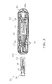
- a puncture wound is formed on the skin by protruding a puncture needle 21 (refer to Fig. 4 ) from an opening formed on a tip of the lancet device 10 while the tip portion is in press-contact with the skin.
- the lancet device 10 includes a lancet 20 and a main body (main body portion) 30.
- the lancet 20 includes the stainless steel puncture needle 21 (refer to Fig.
- the main body 30 includes a coil spring 31 (refer to Fig. 3 ) that applies force to the puncture needle 21 (refer to Fig. 4 ) for making the puncture needle 21 protrude in a predetermined puncture direction and a return spring (not shown) that returns the puncture needle 21 projected by the coil spring 31 into the housing 35.
- front end side is used to refer to the front side in the puncture direction the tip of the puncture needle 21 of the lancet 20 described in the following protrudes in
- rear end side refers to the rear direction in the puncture direction on the opposite side.
- the lancet 20 includes an approximately cylindrical-shaped casing (lancet case) 22, and a puncture body 23 as to be accommodated in the casing 22 so as to be allowed to move to the front and rear end sides of the puncture direction when the lancet device 10 is used.
- Fig. 3 illustrates a cross-sectional view of the casing 22 in order to conveniently explain the interior configuration of the casing 22 having a substantially cylindrical-shape.
- the puncture body 23 is made from resign and formed as a unit with the puncture needle 21 for forming the puncture wound in the skin.
- a tapered portion 23a, a flange portion 23b, a groove (fitting portion) 23c, and an insertion portion 23d are formed at a part of the puncture body 23 formed of resin.
- the tapered portion 23a, flange portion 23b and groove 23c, are formed in the tip side where the puncture needle 21 protrudes.
- the tapered portion 23a is a member that is formed to taper towards the rear end side, with a cross-section perpendicular to the puncture direction formed in an oval shape.
- the flange portion 23b is a disc-shaped member that is formed at the outmost of the front end side of the puncture body 23, and the puncture needle 21 protrudes from the center portion of the disc.
- the groove 23c is a concave portion formed to be interposed between the tapered portion 23a and the flange portion 23b.
- the puncture body 23 along with the lancet holder 32 moves forward in the puncture direction by the elastic force of a coil spring 31 disposed at the rear end side of the lancet holder 32 in the main body 30.
- a cap 24 is attached to the puncture needle 21 so as to cover the tip thereof, and prevents the tip of the puncture needle 21 from being exposed outside before the lancet 20 is used.
- the cap 24 is integrally formed with the puncture needle 21 as is the case with the puncture body 23, and a portion of the cap 24 is connected to the flange portion 23b of the puncture body 23.
- the part where the cap 24 and the flange portion 23b are connected may be separated by twisting and removing the cap 24 at the time of use, and the puncture needle 21 may be exposed inside the casing 22.
- the cap 24 includes a protruding portion 24a, a lid member 24b, and a flange portion 24c.
- the protruding portion 24a is a portion formed to protrude in a direction intersecting the puncture direction, and as illustrated in Fig. 4 , is fitted with a groove 22c that is to be described and is formed in the end portion of the casing 22 on the front end side, when the cap 24 is mounted to the casing 22.
- the lid member 24b functions as a lid for covering the outmost front end portion of the casing 22 before the lancet 20 is used.
- the flange portion 24c is a disc-shaped plate member formed on an upper portion of the cap 24. Blood etc. bleeding from a fingertip etc. at the time of puncturing is prevented from permeating to within the lancet device 10 from the puncture hole (opening portion) 3 5 a of the main body 30.
- the casing 22 is a substantially cylindrical member, and houses the puncture body 23 inside from before use to disposal after use. As shown in Fig.
- the casing 22 includes a cylindrical portion (tubular portion) 22a, a pinching portion (fitting portion) 22b, and a groove 22c.
- the cylindrical portion 22a is formed to have radius that is slightly larger than that of the tapered portion 23a and the flange portion 23b etc. of the puncture body 23.
- the pinching portion 22b is an elastic member that protrudes inwardly from the cylindrical portion 22a of the casing 22, and is formed in the vicinity of the center portion of the casing 22 in the longitudinal direction.
- the puncture body 23 When the lancet 20 is disposed of after use, the puncture body 23 is retracted to the rear end side, and the groove 23c of the puncture body 23 fits with the pinching portion 22b.
- the groove 22c is a concave portion that is formed on the cylindrical portion 22a on the front end side of the casing 22.
- the protruding portion 24a of the cap 24 is engaged with the groove 22c before the lancet 20 is used. Therefore, it is possible to retain the puncture body 23 in the interior of the casing 22 so that the puncture body 23 is not allowed to move to the front and rear end sides in the puncture direction.
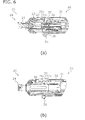
- the main body 30 includes the coil spring 31, the lancet holder 32, a rotator 33, the housing 35, a removing portion 36, a setting release button (shot button) 37, and the stopper plate (shot-ready movement portion) 38 (refer to Fig. 6(b) ), and the above described lancet 20 is attached to the main body 30 from the front end side thereof (refer to Fig. 2 ).
- the coil spring 31 is a member that applies force for moving the puncture body 23 of the lancet 20 forward in the puncture direction and is disposed at the rear end side of the lancet holder 32.
- the rear end portion of the lancet 20 is held as a result of the portion (insertion portion 23d) of the rear end side of the lancet 20 inserted from the puncture hole 35a formed at the tip of the housing 35 being inserted while broadening as a result of pushing into the sleeve 32b (refer to Fig. 5(a) etc.) via the lancet insertion opening 32a (refer to Fig. 5(a) etc.).
- the lancet holder 32 extends along the side surface thereof and has a latch portion (shot-ready movement portion) 32c (refer to Fig. 6(a) ) that elastically deforms in a direction intersecting to the puncture direction.
- the latch portion 32c has a biasing force biasing upwards in the puncture direction and the setting release button 37 is pushed upwards by the biasing force into a shot-ready completion state (shot-possible state).
- the rotator 33 rotates around the axial direction in the circumferential direction when the dial portion is rotated. Further, the rotator 33 includes a spiral-shaped rib that is formed on the inner surface of the cylindrical portion on the front end side of the dial portion.
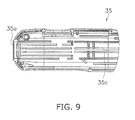
- the housing 35 contains the coil spring 31 described above and the lancet holder 32 etc. built-in, and constitutes the outer wall of the lancet device 10.
- the housing 35 includes the puncture hole 35a at the tip of the front end side, the opening 35b at the tip of the rear end side, and the rib (movement regulating portion) 35c at the inner wall surface (refer to Fig. 9 ).
- the puncture hole 35a enables insertion of the lancet 20 and enables the tip of the needle of the puncture needle 21 to protrude when puncturing is performed.
- the opening 35b houses the rotator 33 and is formed in a circular shape matching the shape of the rotator 33.
- the rib 35c prohibits the lancet 20 from being reinstalled and used for puncturing after use as described in the following by regulating movement to the rear in the puncture direction with abutting of a part of the lancet holder 32, when the lancet 20 is reinstalled after use.
- the removing portion 36 is exposed to a side opposed to the side which the setting release button 37 is exposed on the approximately rectangular housing 35.
- the removing portion 36 is disposed in the interior of the housing 35 so as to make contact with the tip of the rear end side of the casing 22. After completion of the puncture, the removing portion 36 is moved to the front end side. Only the casing 22 abutting with the removing portion 36 then moves forward towards the tip side.
- the pinching portion 22b of the casing 22 then fits with the groove 23c of the puncture body 23.
- the removing portion 36 is moved forward, a part of the removing portion 36 is advanced to the holding portion of the lancet holder 32. Holding of the puncture body 23 (insertion portion 23d) at the lancet holder 32 is then released. It is then possible to remove the lancet 20 from the main body 30. More specifically, in the stage before withdrawal of the lancet 20 from the main body 30, the puncture body 23 is moved to the rear end side relatively with respect to the casing 22 as a result of the casing 22 of the lancet 20 being pushed out more to the front end side than the puncture body 23.
- the tapered portion 23a formed in the vicinity of a central part of the puncture body 23 moves while riding up on the pinching portion 22b formed at the cylindrical portion 22a of the casing 22.
- the vicinity of the pinching portion 22b formed at the cylindrical portion 22a of the casing 22 is elastically deformed.
- the tapered portion 23a then moves to the rear end side.
- the puncture body 23 is then held within the casing 22 at the point where the pinching portion 22b fits with the groove 23c of the puncture body 23. At this time, it is therefore possible to move the puncture body 23 smoothly to the fitting position because the rear end side of the tapered portion 23a is thinner than the front end side thereof.
- the setting release button 37 is exposed at the surface of the opposite side to the removing portion 36 at the substantially right-angled parallelepiped-shaped housing 35. A cocked state is therefore released at the same time as installing the lancet 20 by pressing down the setting release button 37 and puncturing can be carried out.
- the latter stage of movement to a state where a shot is possible at the setting release button 37 is described in the following stage.
- the stopper plate 38 is disposed along a side of the lancet holder 32 within the housing 35. The presence or absence of movement of the setting release button 37 to a shot-ready state is then decided by changing the amount of movement in the puncture direction at the time of installation of the lancet 20 before use and at the time of re-installation of the lancet 20 after use.
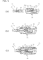
- a re-cocking lever provided normally in a typical lancet device is not provided in the lancet device 10 of the embodiment. It is therefore possible to prevent a used puncture needle from being re-cocked and shot after puncturing once by not providing a mechanism enabling re-cocking. It is therefore possible to reliably reduce the danger in the case of installation of used lancets. "Flow from installation of unused lancet 20 to removal of lancet 20 after puncturing" As shown in Fig 5(a) , when the use of the lancet device 10 of the present embodiment begins, an unused, new lancet 20 is first inserted into the puncture opening 35a of the main body 30.
- the insertion portion 23d formed at the tip of the rear end side of the puncture body 23 is inserted into the lancet insertion opening 32a of the tip of the lancet holder 32.
- the rear end portion (the insertion portion 23d) of the puncture body 23 is inserted into the lancet holder 32 while the sleeve 32b spreads out to the outer side.
- the puncture body 23 is then held at the front end portion (lancet insertion opening 32a) of the lancet holder 32 so that the outer peripheral surface of the puncture body 23 is grasped by the sleeve 32b.
- the rear end portion of the casing 22 abuts with part of the stopper plate 38 while the rear end portion (insertion portion 23d) of the puncture body 23 pushes the lancet holder 32 into the rear.
- the latch portion 32c of the lancet holder 32 is pushed down by the rib 35d formed at the inner wall surface of the housing 35.
- the setting release button 37 pushed upwards by the latch portion 32c is in a state where upward movement is regulated by catching on the protruding portion 37a at the opening 38a formed at a part of the stopper plate 38.
- the cap 24 that is formed as a unit with the puncture body 23 is removed to expose the puncture needle 21.
- the cap 24 is connected partially to a surface of the flange portion 23b of the puncture body 23 on the front end side. Therefore, the cap 24 is removed when the connected portion is torsionally-sheared by rotating the cap 24.
- the pulling force to the front end side is applied for the cap 24 to be removed. Therefore, the pulling force to the front end side is also applied to the puncture body 23, a portion of which is connected to the cap 24.
- the tip of the rear end side of the puncture body 23 is held by the lancet holder 32.
- the force of fitting of the puncture body 23 and the lancet holder 32 is then larger than the force required to detach the cap 24 from the puncture body 23.
- the puncture body 23 is not pulled out together with the cap 24 but rather is held within the casing 22.
- the puncture needle 21 protrudes a predetermined amount from the puncture hole 35a formed in the very tip side of the main body 30 and puncturing can be performed. Then, the puncture needle 21 is brought back to the casing 22 again by means of the spring force of the return spring (not illustrated in the figures) immediately after a puncture is performed. After the puncture is completed, the lancet 20 is removed from the main body 30 and is then disposed. Removal of the lancet 20 from the main body 30 is done using the removing portion 36.
- the hold on the puncture body 23 by the lancet holder 32 is released by moving the removing portion 36 towards the front end side, and the lancet 20 may be removed from the puncture hole 35a.
- the removing portion 36 is moved to the front end side, only the casing 22 is first moved to the front end side. Accordingly, the puncture body 23 that is being retained in the lancet holder 32 is moved to the rear end side relative to the casing 22.
- the tapered portion 23a that is formed in the vicinity of the center portion of the puncture body 23 is moved while pressing and enlarging the pinching portion 22b formed on the cylindrical portion 22a of the casing 22 to the outside.
- the pinching portion 22b of the casing 22 is therefore engaged with the groove 23c of the puncture body 23.
- This engaged state is tightly formed, and therefore this makes it possible to prevent the tip of the puncture needle 21 from protruding from the front end side of the casing 22 after the lancet 20 is removed from the main body 30.
- the puncture needle 21 is prevented from protruding with the cap 24 before the lancet 20 is used, and the puncture body 23 is retained in the casing 22 by means of the engaged state with large engagement force after the lancet 20 is used. Therefore, it is possible to avoid the danger of the puncture needle 21 projecting from the tip of the casing 22 before and after the lancet 20 is used.
- the sleeve 32b of the lancet holder 32 moves relatively in the tip direction with respect to the lancet insertion opening 32a.
- the holding of the puncture body 23 is then released by the lancet holder 32 as a result of the force encompassing the insertion portion 23d of the puncture body 23 weakening.
- the lancet 20 is removed from the main body 30 after use and is disposed.
- the puncture body 23 is tightly retained in the casing 22 by means of the engagement force in the removed lancet 20.
- the lancet 20 removed once from the main body 30 holds the puncture body 23 within the casing 22 at a different position to before use. It is therefore possible to make it difficult to install the lancet 20 in the main body 30 again for reuse after use compared to the lancet of the related art.
- the lancet device 10 of the embodiment As described above, with the lancet device 10 of the embodiment, reuse of the lancet 20 after use is difficult because the puncture body 23 is firmly held within the casing 22. However, there is also the fear that the lancet 20 will be forcibly installed at the main body 30 for reuse after being used.
- the following mechanism is therefore further provided at the lancet device 10 of the embodiment as a mechanism for reliably inhibiting reuse of a used lancet 20.
- the used lancet 20 is held to the rear end side within the casing 22 as shown in Fig. 7(a) whereas the puncture body 23 is held comparatively to the front end side within the casing 22, as shown in Fig. 4 .
- the insertion portion 23d formed at the tip of the rear end side of the puncture body 23 is inserted into the lancet insertion opening 32a of the tip of the lancet holder 32.
- the rear end portion (insertion portion 23d) of the puncture body 23 enters the lancet holder 32 while the sleeve 32b spreads out to the outer side.
- the puncture body 23 is then held at the front end portion (lancet insertion opening 32a) of the lancet holder 32 so that the outer peripheral surface of the puncture body 23 is grasped by the sleeve 32b.
- the cause of the difference in movement within the main body 30 is the difference in the holding position for the puncture body 23 with respect to the casing 22 before installation. In the lancet 20 after use, the puncture body 23 is held further towards the rear end with respect to the casing 22.
- the timing with which the rear end of the puncture body 23 comes into contact with the lancet holder 32 is therefore faster compared to the lancet 20 before use.
- the lancet holder 32 reaches a predetermined limit position and the lancet 20 cannot be inserted any further back.
- the casing 22 then abuts with the stopper plate 38 and the latch portion 32c of the lancet holder 32 is opened up from the rib 35d formed at the inner wall surface of the housing 35 by the stopper plate 38 so as to move upwards.
- the setting release button 37 is then pushed upwards and the achievement of a shot-ready completion state can be inhibited.
- the setting release button 37 for enabling puncturing is pushed up so as to prohibit to move the used lancet 20 to a shot-ready completion state even in cases where the used lancet 20 is re-installed in the main body 30.
- the puncture body 23 being forcibly held within the casing 22 during removal from the main body 30 after puncturing, when a used lancet 20 is installed to the main body 30, movement to a shot-ready completion state of the lancet device 10 is inhibited. This means that the danger of infection etc. with infectious diseases as a result of re-puncturing using a used lancet 20 at the side of the lancet device 10 is reliably avoided and it is possible to provide a very safe lancet device 10.
- the lancet device 10 of the embodiment can also use a combination of two structures as a shot prevention mechanism for preventing re-shooting using a used lancet 20.
- a first structure as shown in Fig. 4 and Fig. 7(a) , the positions for holding the puncture body 23 within the casing 22 are different before and after use.
- a second structure as shown in Fig. 7(a) to Fig. 8(b) , the position for holding the puncture body 23 within the casing 22 being different for before and after use is utilized.
- a fitting portion composed of the groove 22c and the pinching portion 22b which are formed at the inner wall surface of the casing 22, and the groove 23c and the protruding portion 24a which are formed respectively at the puncture body 23 and the cap 24 is adopted as a mechanism for changing the holding position of the puncture body 23 within the casing 22 before and after use.
- the protruding portion 24a of the cap 24 formed integrally with the puncture body 23 is held in the groove 22c formed towards the tip of the casing 22.
- a portion of the groove 23c of the puncture body 23 can be forcibly held by the pinching portion 22b of the casing 22 in the lancet 20 removed from the main body 30 after puncturing.
- the puncture body 23 is forcibly held within the casing 22, thereby the danger of the puncture needle 21 protruding from the end of the casing 22 is avoided after removal of the lancet 20.
- movement to the shot-ready completion state is performed by pushing the setting release button 37 upwards, as shown in Fig. 6(b) . It is therefore possible to reliably prevent the used lancet 20 from being used for puncturing again because it is not possible to push the setting release button 37 upwards in order to move to a shot-ready completion state when a used lancet 20 is installed.
- the stopper plate 38 is mainly used as the shot-ready movement portion for moving the structure in the main body 30 with the lancet 20 fitted within to the shot-ready completion state.
- the rear end portion of the casing 22 of the lancet 20 moves the stopper plate 38 so as to release the latch portion 32c of the lancet holder 32. It is then possible for the setting release button 37 to be pushed up.
- the present invention is not limited to this configuration.
- the puncture body 23 it is also possible for the puncture body 23 to be held within the casing 22 after puncturing in such a manner that the position of the puncture body 23 with respect to the casing 22 while removed from the main body 30 after puncturing is further to the front side in a puncture direction than the position of the puncture body 23 with respect to the casing 22 while installed at the main body 30 before puncturing.
- the present invention is not limited to this configuration.
- the configuration where a re-cocking lever is omitted such as in the above embodiment is preferable from the point of view of providing a highly safe lancet device that avoids the danger of carrying out re-cocking of a lancet once again and performing puncturing with a lancet that has been left in after puncturing.
- the present invention is not limited to this configuration.
- the forcible holding of the puncture body 23 within the casing 22 of the latter stage is not an essential aspect of the configuration and can also simply be changed to a holding position of the puncture body 23 with respect to the casing 22 before and after use.
- the present invention is not limited to this configuration.
- the lancet device of the present invention is capable of ensuring a high degree of safety after use with a simple structure and is therefore widely applicable to puncture apparatus where a puncture needle protrudes in a predetermined direction and puncturing is carried out.
Landscapes
- Health & Medical Sciences (AREA)
- Life Sciences & Earth Sciences (AREA)
- Heart & Thoracic Surgery (AREA)
- Medical Informatics (AREA)
- Biophysics (AREA)
- Pathology (AREA)
- Engineering & Computer Science (AREA)
- Biomedical Technology (AREA)
- Hematology (AREA)
- Physics & Mathematics (AREA)
- Molecular Biology (AREA)
- Surgery (AREA)
- Animal Behavior & Ethology (AREA)
- General Health & Medical Sciences (AREA)
- Public Health (AREA)
- Veterinary Medicine (AREA)
- Dermatology (AREA)
- Measurement Of The Respiration, Hearing Ability, Form, And Blood Characteristics Of Living Organisms (AREA)
Applications Claiming Priority (2)
| Application Number | Priority Date | Filing Date | Title |
|---|---|---|---|
| JP2006065789 | 2006-03-10 | ||
| PCT/JP2007/054634 WO2007105617A1 (ja) | 2006-03-10 | 2007-03-09 | ランセットデバイス |
Publications (2)
| Publication Number | Publication Date |
|---|---|
| EP1994884A1 true EP1994884A1 (de) | 2008-11-26 |
| EP1994884A4 EP1994884A4 (de) | 2012-05-23 |
Family
ID=38509440
Family Applications (1)
| Application Number | Title | Priority Date | Filing Date |
|---|---|---|---|
| EP07738119A Withdrawn EP1994884A4 (de) | 2006-03-10 | 2007-03-09 | Lanzettenvorrichtung |
Country Status (5)
| Country | Link |
|---|---|
| US (1) | US20090093832A1 (de) |
| EP (1) | EP1994884A4 (de) |
| JP (1) | JP5021619B2 (de) |
| CN (1) | CN101400302B (de) |
| WO (1) | WO2007105617A1 (de) |
Cited By (1)
| Publication number | Priority date | Publication date | Assignee | Title |
|---|---|---|---|---|
| CN112603308A (zh) * | 2020-12-17 | 2021-04-06 | 重庆市公共卫生医疗救治中心 | 一种防止艾滋病交叉感染的抽血装置 |
Families Citing this family (6)
| Publication number | Priority date | Publication date | Assignee | Title |
|---|---|---|---|---|
| US8932314B2 (en) * | 2008-05-09 | 2015-01-13 | Lifescan Scotland Limited | Prime and fire lancing device with contacting bias drive and method |
| US8679144B2 (en) | 2008-06-05 | 2014-03-25 | Lightnix, Inc. | Puncture needle cartridge and puncture device |
| JP2010233803A (ja) * | 2009-03-31 | 2010-10-21 | Sysmex Corp | 微細孔形成用穿刺装置 |
| EP2260898A1 (de) * | 2009-06-10 | 2010-12-15 | Ulrich Schäfer | Führungsdraht und Verfahren zu dessen Verwendung |
| JP6014022B2 (ja) * | 2011-03-30 | 2016-10-25 | テルモ株式会社 | 穿刺装置 |
| GB2489740A (en) * | 2011-04-08 | 2012-10-10 | Owen Mumford Ltd | Means for securely retaining a lancet in a lancing device |
Family Cites Families (18)
| Publication number | Priority date | Publication date | Assignee | Title |
|---|---|---|---|---|
| JPH03115405U (de) * | 1990-03-09 | 1991-11-28 | ||
| CA2079192C (en) * | 1992-09-25 | 1995-12-26 | Bernard Strong | Combined lancet and multi-function cap and lancet injector for use therewith |
| DE4320463A1 (de) * | 1993-06-21 | 1994-12-22 | Boehringer Mannheim Gmbh | Blutlanzettenvorrichtung zur Entnahme von Blut für Diagnosezwecke |
| US6126617A (en) * | 1995-01-26 | 2000-10-03 | Ascendia Ab | Impact-damped biopsy instrument |
| US5628764A (en) * | 1995-03-21 | 1997-05-13 | Schraga; Steven | Collar lancet device |
| US5873887A (en) * | 1996-10-25 | 1999-02-23 | Bayer Corporation | Blood sampling device |
| US5954738A (en) * | 1997-07-31 | 1999-09-21 | Bayer Corporation | Blood sampling device with lancet damping system |
| US5913843A (en) * | 1997-11-26 | 1999-06-22 | Jentzen; S. William | Dampening device for spring movement |
| JP3697100B2 (ja) | 1999-03-04 | 2005-09-21 | テルモ株式会社 | 穿刺具 |
| US6558402B1 (en) * | 1999-08-03 | 2003-05-06 | Becton, Dickinson And Company | Lancer |
| DE10053974A1 (de) * | 2000-10-31 | 2002-05-29 | Roche Diagnostics Gmbh | System zur Blutentnahme |
| US6607511B2 (en) * | 2001-08-09 | 2003-08-19 | Mdc Investment Holdings, Inc. | Medical device with safety flexible needle |
| JP2004113580A (ja) * | 2002-09-27 | 2004-04-15 | Ra Systems:Kk | ランセット |
| JP2004290390A (ja) * | 2003-03-26 | 2004-10-21 | Bionics Corp | 穿刺針、およびその組立方法 |
| JP2005342325A (ja) * | 2004-06-04 | 2005-12-15 | Matsushita Electric Ind Co Ltd | 穿刺針カートリッジ |
| EP1815792B1 (de) * | 2004-10-25 | 2016-06-01 | ARKRAY, Inc. | Lanzette und lanzettenvorrichtung mit derselben |
| WO2006118224A1 (ja) * | 2005-04-28 | 2006-11-09 | Matsushita Electric Industrial Co., Ltd. | 穿刺具、及び穿刺針カートリッジ |
| JP3115405U (ja) * | 2005-08-03 | 2005-11-04 | テルモ株式会社 | 穿刺針及びそのキャップ |
-
2007
- 2007-03-09 JP JP2008505101A patent/JP5021619B2/ja not_active Expired - Fee Related
- 2007-03-09 WO PCT/JP2007/054634 patent/WO2007105617A1/ja not_active Ceased
- 2007-03-09 EP EP07738119A patent/EP1994884A4/de not_active Withdrawn
- 2007-03-09 US US12/280,898 patent/US20090093832A1/en not_active Abandoned
- 2007-03-09 CN CN2007800085366A patent/CN101400302B/zh not_active Expired - Fee Related
Cited By (2)
| Publication number | Priority date | Publication date | Assignee | Title |
|---|---|---|---|---|
| CN112603308A (zh) * | 2020-12-17 | 2021-04-06 | 重庆市公共卫生医疗救治中心 | 一种防止艾滋病交叉感染的抽血装置 |
| CN112603308B (zh) * | 2020-12-17 | 2022-10-04 | 重庆市公共卫生医疗救治中心 | 一种防止艾滋病交叉感染的抽血装置 |
Also Published As
| Publication number | Publication date |
|---|---|
| WO2007105617A1 (ja) | 2007-09-20 |
| US20090093832A1 (en) | 2009-04-09 |
| CN101400302A (zh) | 2009-04-01 |
| CN101400302B (zh) | 2010-11-03 |
| JP5021619B2 (ja) | 2012-09-12 |
| JPWO2007105617A1 (ja) | 2009-07-30 |
| EP1994884A4 (de) | 2012-05-23 |
Similar Documents
| Publication | Publication Date | Title |
|---|---|---|
| EP1994884A1 (de) | Lanzettenvorrichtung | |
| US8926645B2 (en) | Disposable lancing device | |
| US8361099B2 (en) | Puncture aid with protection against reuse | |
| JP5896927B2 (ja) | 安全針アセンブリ | |
| US8679145B2 (en) | Puncture device | |
| KR20070011514A (ko) | 란셋 어셈블리 | |
| US20090299398A1 (en) | Lancet Assembly and Pricking Device | |
| JP4969247B2 (ja) | ランセットおよびこれを備えたランセットデバイス | |
| EP1992285A1 (de) | Lanzettenvorrichtung | |
| JP4507600B2 (ja) | 採血用穿刺器具、および穿刺針ユニット | |
| JP2005312763A (ja) | 穿刺針カートリッジ、穿刺器具、先端ユニットおよびアダプタ | |
| JP4820822B2 (ja) | 穿刺器具 | |
| KR20130041288A (ko) | 란셋 시스템의 재사용 방지 | |
| JP4736042B2 (ja) | 留置針 | |
| JP2006081751A (ja) | 針プロテクター付きランセット及びこれを装着する穿刺具 | |
| JP4585040B2 (ja) | 穿刺針カートリッジ | |
| JP2010115528A5 (de) | ||
| HK1128397A (en) | Lancet assembly and piercing device |
Legal Events
| Date | Code | Title | Description |
|---|---|---|---|
| PUAI | Public reference made under article 153(3) epc to a published international application that has entered the european phase |
Free format text: ORIGINAL CODE: 0009012 |
|
| 17P | Request for examination filed |
Effective date: 20080918 |
|
| AK | Designated contracting states |
Kind code of ref document: A1 Designated state(s): AT BE BG CH CY CZ DE DK EE ES FI FR GB GR HU IE IS IT LI LT LU LV MC MT NL PL PT RO SE SI SK TR |
|
| A4 | Supplementary search report drawn up and despatched |
Effective date: 20120420 |
|
| RIC1 | Information provided on ipc code assigned before grant |
Ipc: A61B 5/151 20060101AFI20120416BHEP |
|
| DAX | Request for extension of the european patent (deleted) | ||
| STAA | Information on the status of an ep patent application or granted ep patent |
Free format text: STATUS: THE APPLICATION IS DEEMED TO BE WITHDRAWN |
|
| 18D | Application deemed to be withdrawn |
Effective date: 20121120 |