EP1995000A1 - Befestigungsvorrichtung für abstreiferplatte - Google Patents
Befestigungsvorrichtung für abstreiferplatte Download PDFInfo
- Publication number
- EP1995000A1 EP1995000A1 EP07714515A EP07714515A EP1995000A1 EP 1995000 A1 EP1995000 A1 EP 1995000A1 EP 07714515 A EP07714515 A EP 07714515A EP 07714515 A EP07714515 A EP 07714515A EP 1995000 A1 EP1995000 A1 EP 1995000A1
- Authority
- EP
- European Patent Office
- Prior art keywords
- lock
- stripper plate
- piece
- adaptor
- punch
- Prior art date
- Legal status (The legal status is an assumption and is not a legal conclusion. Google has not performed a legal analysis and makes no representation as to the accuracy of the status listed.)
- Granted
Links
Images



Classifications
-
- B—PERFORMING OPERATIONS; TRANSPORTING
- B21—MECHANICAL METAL-WORKING WITHOUT ESSENTIALLY REMOVING MATERIAL; PUNCHING METAL
- B21D—WORKING OR PROCESSING OF SHEET METAL OR METAL TUBES, RODS OR PROFILES WITHOUT ESSENTIALLY REMOVING MATERIAL; PUNCHING METAL
- B21D45/00—Ejecting or stripping-off devices arranged in machines or tools dealt with in this subclass
- B21D45/003—Ejecting or stripping-off devices arranged in machines or tools dealt with in this subclass in punching machines or punching tools
- B21D45/006—Stripping-off devices
-
- B—PERFORMING OPERATIONS; TRANSPORTING
- B21—MECHANICAL METAL-WORKING WITHOUT ESSENTIALLY REMOVING MATERIAL; PUNCHING METAL
- B21D—WORKING OR PROCESSING OF SHEET METAL OR METAL TUBES, RODS OR PROFILES WITHOUT ESSENTIALLY REMOVING MATERIAL; PUNCHING METAL
- B21D28/00—Shaping by press-cutting; Perforating
-
- B—PERFORMING OPERATIONS; TRANSPORTING
- B21—MECHANICAL METAL-WORKING WITHOUT ESSENTIALLY REMOVING MATERIAL; PUNCHING METAL
- B21D—WORKING OR PROCESSING OF SHEET METAL OR METAL TUBES, RODS OR PROFILES WITHOUT ESSENTIALLY REMOVING MATERIAL; PUNCHING METAL
- B21D28/00—Shaping by press-cutting; Perforating
- B21D28/02—Punching blanks or articles with or without obtaining scrap; Notching
- B21D28/14—Dies
-
- B—PERFORMING OPERATIONS; TRANSPORTING
- B21—MECHANICAL METAL-WORKING WITHOUT ESSENTIALLY REMOVING MATERIAL; PUNCHING METAL
- B21D—WORKING OR PROCESSING OF SHEET METAL OR METAL TUBES, RODS OR PROFILES WITHOUT ESSENTIALLY REMOVING MATERIAL; PUNCHING METAL
- B21D45/00—Ejecting or stripping-off devices arranged in machines or tools dealt with in this subclass
- B21D45/06—Stripping-off devices
- B21D45/08—Stripping-off devices interrelated with motion of tool
-
- B—PERFORMING OPERATIONS; TRANSPORTING
- B26—HAND CUTTING TOOLS; CUTTING; SEVERING
- B26D—CUTTING; DETAILS COMMON TO MACHINES FOR PERFORATING, PUNCHING, CUTTING-OUT, STAMPING-OUT OR SEVERING
- B26D7/00—Details of apparatus for cutting, cutting-out, stamping-out, punching, perforating, or severing by means other than cutting
- B26D7/18—Means for removing cut-out material or waste
- B26D7/1818—Means for removing cut-out material or waste by pushing out
-
- B—PERFORMING OPERATIONS; TRANSPORTING
- B26—HAND CUTTING TOOLS; CUTTING; SEVERING
- B26D—CUTTING; DETAILS COMMON TO MACHINES FOR PERFORATING, PUNCHING, CUTTING-OUT, STAMPING-OUT OR SEVERING
- B26D7/00—Details of apparatus for cutting, cutting-out, stamping-out, punching, perforating, or severing by means other than cutting
-
- B—PERFORMING OPERATIONS; TRANSPORTING
- B26—HAND CUTTING TOOLS; CUTTING; SEVERING
- B26F—PERFORATING; PUNCHING; CUTTING-OUT; STAMPING-OUT; SEVERING BY MEANS OTHER THAN CUTTING
- B26F1/00—Perforating; Punching; Cutting-out; Stamping-out; Apparatus therefor
- B26F1/38—Cutting-out; Stamping-out
- B26F1/40—Cutting-out; Stamping-out using a press, e.g. of the ram type
-
- Y—GENERAL TAGGING OF NEW TECHNOLOGICAL DEVELOPMENTS; GENERAL TAGGING OF CROSS-SECTIONAL TECHNOLOGIES SPANNING OVER SEVERAL SECTIONS OF THE IPC; TECHNICAL SUBJECTS COVERED BY FORMER USPC CROSS-REFERENCE ART COLLECTIONS [XRACs] AND DIGESTS
- Y10—TECHNICAL SUBJECTS COVERED BY FORMER USPC
- Y10T—TECHNICAL SUBJECTS COVERED BY FORMER US CLASSIFICATION
- Y10T83/00—Cutting
- Y10T83/202—With product handling means
- Y10T83/2092—Means to move, guide, or permit free fall or flight of product
- Y10T83/2096—Means to move product out of contact with tool
- Y10T83/2135—Moving stripper timed with tool stroke
- Y10T83/215—Carried by moving tool element or its support
- Y10T83/2155—Stripper biased against product
- Y10T83/2159—By spring means
-
- Y—GENERAL TAGGING OF NEW TECHNOLOGICAL DEVELOPMENTS; GENERAL TAGGING OF CROSS-SECTIONAL TECHNOLOGIES SPANNING OVER SEVERAL SECTIONS OF THE IPC; TECHNICAL SUBJECTS COVERED BY FORMER USPC CROSS-REFERENCE ART COLLECTIONS [XRACs] AND DIGESTS
- Y10—TECHNICAL SUBJECTS COVERED BY FORMER USPC
- Y10T—TECHNICAL SUBJECTS COVERED BY FORMER US CLASSIFICATION
- Y10T83/00—Cutting
- Y10T83/929—Tool or tool with support
- Y10T83/9457—Joint or connection
- Y10T83/9473—For rectilinearly reciprocating tool
- Y10T83/9476—Tool is single element with continuous cutting edge [e.g., punch, etc.]
Definitions
- the present invention relates to a stripper plate mounting apparatus for mounting a stripper plate in a detachable and replaceable manner on a punch die used for punch press. Specifically, the present invention relates to a stripper plate mounting apparatus capable of easily attaching and detaching a stripper plate to and from a punch die.
- a punch die used for punch press is provided with a stripper plate for pressing down the die to a plate-shaped workpiece, while the workpiece is processed in a punching process with a punch, for the purpose of preventing a deformation of punching during the punching process.
- the punch is removed from the punch die, and the edge part is ground again. In this case, it is necessary to remove the stripper plate from the punch die.
- Patent Document 1 proposes a configuration which allows the stripper plate to be mounted on and detached from the punch die easily. Such a configuration is disclosed, for example, in a Patent Brochure of Japanese National Publication of Translation Version (Kohyo) No. 2005-528986 (Patent Document 1).
- a punch block 17 is attached in a detachable and replaceable manner to the other end side of the punch body 3 with a bolt 15.
- a punch edge part 19 is formed in a front end portion of this punch block 17.
- a disk-shaped stripper plate 21 surrounding this punch edge part 19 is mounted in a detachable and replaceable manner on a front end portion of the punch guide 5.
- lock buttons 31 are respectively provided, movably in radial directions (radius directions), in yet other multiple locations of the outer circumferential surface of the holder 23.
- the lock buttons 31 are engageable with, and detachable from, lock holes 29 which extend in the radial directions (radius directions), and which are respectively provided to multiple locations in the punch guide 5.
- the lock buttons 31 are always biased outward by their respective built-in springs 33.
- the stripper plate 21 is detached from the punch guide 5 and replaced with a new one in a following way. Specifically, the lock buttons 31 provided in the multiple locations are simultaneously pressed against the respective springs 33, and thereby the engagement of the lock holes 29 with the respective lock buttons 31 is released. With this operation, the holder 23 is moved upward in Fig. 1 by the biasing forces from the respective springs 25. Once the holder 23 is moved upward, the plate lock-holding pieces 27 become slidable outward, and thus the fixation of the stripper plate 21 is released. For this reason, it is possible to remove the stripper plate 21 from the holder 23.
- the stripper plate 21 is fixed. Specifically, once the holder 23 is pressed and moved toward an inner side of the punch guide 5, the plate lock-holding pieces 27 move inward in their respective radial directions (radius directions), and thus integrally fix the stripper plate 21. Thereafter, once the holder 23 is pressed, the lock buttons 31 provided to the holder 23 engage with the respective lock holes 29 provided to the punch guide 5, and thus the holder 23 is fixed thereto. Thereby, the stripper plate 21 is integrated with the punch guide 5.
- the conventional configuration has a problem that the multiple lock buttons 31 have to be simultaneously pressed against the respective springs 33.
- the holder 23 is pushed upward by the biasing forces from the springs 25, the holder 23 may sometimes be pushed up so forcefully and abruptly, if the punch edge part 19 in the punch block 17 is relatively large and the stripper plate 21 is relatively light in weight, that there is another problem that an operator feels that the stripper plate is unstable.
- some plate lock-holding pieces 27 may break. For these reasons, further improvements are requested.
- a first aspect of the present invention is a stripper plate mounting apparatus for mounting a stripper plate in a detachable and replaceable manner above a front end portion of a punch guide into which a punch including an edge part in its front end portion is fitted movably upward and downward.
- the apparatus includes: an adaptor detachably provided to the front end portion of the punch guide, the adaptor holding the stripper plate, and multiple lock parts being respectively formed in multiple locations on the adaptor; and multiple lock mechanisms provided in multiple locations on an outer periphery of the front end portion of the punch guide so as to correspond to locations of multiple lock parts formed in the stripper plate, respectively.
- the lock mechanisms each include: a lock piece capable of being locked to, and detached from, a corresponding one of the lock parts formed in the adaptor; biasing means for always biasing the lock piece outward in a radial direction (a radius direction); and a lock-holding piece for locking and holding the lock piece to an inward position when the lock piece is pressed and moved inward in the radial direction (the radius direction).
- the adaptor is fixed to the punch guide by use of the lock mechanisms.
- a fourth aspect of the present invention which depends on any one aspect of the first to third aspects is the stripper plate mounting apparatus, in which the lock-holding piece protrudes more outward than the lock piece when the adaptor is removed from the punch guide.
- the multiple lock pieces can be individually pressed, and thus the multiple lock pieces should not be simultaneously operated by pressing them. This makes it possible to release the fixation easily.
- a punch die 1 is almost the same as the configuration of the conventional type of general punch die.
- a punch body 3 is fitted into a cylindrical punch guide 5 to be movable upward and downward.
- This punch body 3 is provided with a punch block 17 which has a punch edge part 19 formed in its front end portion.
- a cylindrical adaptor 35 including a disk-shaped stripper plate 21 in a detachable and replaceable manner is mounted on the front end portion of the punch guide 5 in a fixable and releasable manner.
- an annular attachment step part 37 to mount the stripper plate 21 is formed in the front-end-side inner circumferential surface of the adaptor 35.
- the adaptor 35 integrally includes a thin cylindrical fit-on part 39 which fits onto the outer circumferential surface of a front end portion of the punch guide 5.
- lock holes 41 penetrating the cylindrical fit-on part 39 in the radial directions (in the radius directions) are respectively formed in multiple locations on the cylindrical fit-on part 39 in the circumferential direction.
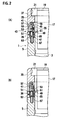
- lock mechanisms 43 capable of fixing the adaptor 35 to the punch guide 5 are provided in multiple locations on the outer periphery of the front end portion of the punch guide 5, respectively. More specifically, a first concave part 45 and a second concave part 47 both being open outward in a radial direction (outward in a radius direction) are provided in each of the multiple locations on the outer periphery of the front end portion of the punch guide 5 in a way that the first concave part 45 and the second concave part 47 keep away from each other in the longitudinal direction of the punch guide 5.
- the first concave part 45 is located closer to the front end side of the punch guide 5 than the second concave part 47.
- a long hole 51 elongated in the radial direction (in the radius direction) penetrates a partition wall 49 for demarcating the first concave part 45 and the second concave part 47.
- a lock piece 53 engageable with and detachable from (capable of being locked to and being detached from) its corresponding lock hole 41 is installed movable in a radial direction (a radius direction).
- This lock piece 53 is always biased outward in the radial direction by biasing means (biasing module) 55, such as a coil spring, which is set resiliently in the first concave part 45.
- biasing means biasing module
- a come-out prevention pin 57 is provided to the lock piece 53.
- a front end portion of this come-out prevention pin 57 movably engages with a long hole 58 elongated in the radial direction (a radius direction), the hole being formed in the punch guide 5.
- a lock-holding piece 63 is installed inside the second concave part 47.
- the lock-holding piece 63 is movable along the second concave part 47 in a radial direction (in the radius direction), as well as is movable in directions in which the lock-holding piece 63 approaches the lock piece 53, and in which the lock-holding piece 63 is detached from the lock piece 53.
- This lock-holding piece 63 includes an engagement pin 65 as a convex part which is engageable with and detachable from the engagement concave part 61 provided to the lock piece 53 while penetrating the long hole 51.
- the lock-holding piece 63 is always biased to the side of the lock piece 53 by biasing means 67, such as a coil spring, which is set resiliently in the second concave part 47. Moreover, when the lock piece 53 and the lock-holding piece 63 are both moved outward in the radial direction, the lock-holding piece 63 is in the state of protruding slightly more outward than the lock piece 53.
- biasing means 67 such as a coil spring
- the present invention is not limited to the foregoing descriptions for the embodiment of the present invention.
- the present invention can be carried out in various modes by modifying the present invention depending on the necessity.
Landscapes
- Engineering & Computer Science (AREA)
- Mechanical Engineering (AREA)
- Life Sciences & Earth Sciences (AREA)
- Forests & Forestry (AREA)
- Punching Or Piercing (AREA)
- Perforating, Stamping-Out Or Severing By Means Other Than Cutting (AREA)
- Mounting, Exchange, And Manufacturing Of Dies (AREA)
Applications Claiming Priority (2)
| Application Number | Priority Date | Filing Date | Title |
|---|---|---|---|
| JP2006048600A JP4871609B2 (ja) | 2006-02-24 | 2006-02-24 | ストリッパープレート装着装置 |
| PCT/JP2007/052989 WO2007097291A1 (ja) | 2006-02-24 | 2007-02-19 | ストリッパープレート装着装置 |
Publications (3)
| Publication Number | Publication Date |
|---|---|
| EP1995000A1 true EP1995000A1 (de) | 2008-11-26 |
| EP1995000A4 EP1995000A4 (de) | 2011-06-01 |
| EP1995000B1 EP1995000B1 (de) | 2012-10-31 |
Family
ID=38437331
Family Applications (1)
| Application Number | Title | Priority Date | Filing Date |
|---|---|---|---|
| EP20070714515 Not-in-force EP1995000B1 (de) | 2006-02-24 | 2007-02-19 | Befestigungsvorrichtung für abstreiferplatte |
Country Status (7)
| Country | Link |
|---|---|
| US (1) | US8037793B2 (de) |
| EP (1) | EP1995000B1 (de) |
| JP (1) | JP4871609B2 (de) |
| KR (1) | KR101032357B1 (de) |
| CN (1) | CN101389422B (de) |
| TW (1) | TWI307294B (de) |
| WO (1) | WO2007097291A1 (de) |
Families Citing this family (3)
| Publication number | Priority date | Publication date | Assignee | Title |
|---|---|---|---|---|
| US9186717B2 (en) * | 2012-10-19 | 2015-11-17 | Mate Precision Tooling, Inc. | Punch assembly with separate adjustable punch guiding shim block |
| JP6769606B2 (ja) * | 2016-08-19 | 2020-10-14 | 株式会社コニック | パンチ金型 |
| WO2018151337A1 (ko) * | 2017-02-14 | 2018-08-23 | 이윤선 | 프레스 금형용 스트리핑 장치 |
Family Cites Families (12)
| Publication number | Priority date | Publication date | Assignee | Title |
|---|---|---|---|---|
| US4248111A (en) * | 1979-07-16 | 1981-02-03 | Wilson Tool Company | Punch guide assembly |
| US5081891A (en) * | 1988-08-19 | 1992-01-21 | Mate Punch & Die Co. | Punch assembly |
| US5127293A (en) * | 1990-07-26 | 1992-07-07 | Strippit, Inc. | Stripper plate retaining ring |
| JPH04167934A (ja) | 1990-11-01 | 1992-06-16 | Mate Punch & Die Co | 打抜き機組立体 |
| JP2810634B2 (ja) * | 1995-03-30 | 1998-10-15 | 株式会社アマダメトレックス | パンチング金型 |
| US6082516A (en) * | 1998-01-22 | 2000-07-04 | Amada Engineering & Service Co., Inc. | Variable height adjustable punch assembly having quick release stripper plate |
| US6276247B1 (en) * | 2000-03-03 | 2001-08-21 | Strippit, Inc. | Adjustable punch assembly with releasable locking |
| JP4349762B2 (ja) * | 2000-10-26 | 2009-10-21 | 株式会社アマダ | 上型装置 |
| US6895849B2 (en) * | 2002-06-07 | 2005-05-24 | Wilson Tool International, Inc. | Stripper plate retention system |
| US7479004B2 (en) * | 2002-06-18 | 2009-01-20 | Amada Company, Limited | Die and die device |
| JP2006048600A (ja) | 2004-08-09 | 2006-02-16 | Hiroyuki Iwanami | 娯楽利用者支援方法 |
| WO2006054694A1 (ja) * | 2004-11-19 | 2006-05-26 | Amada Company, Limited | パンチ金型 |
-
2006
- 2006-02-24 JP JP2006048600A patent/JP4871609B2/ja not_active Expired - Fee Related
-
2007
- 2007-02-19 KR KR1020087020620A patent/KR101032357B1/ko not_active Expired - Fee Related
- 2007-02-19 CN CN2007800064783A patent/CN101389422B/zh not_active Expired - Fee Related
- 2007-02-19 WO PCT/JP2007/052989 patent/WO2007097291A1/ja not_active Ceased
- 2007-02-19 EP EP20070714515 patent/EP1995000B1/de not_active Not-in-force
- 2007-02-19 US US12/280,058 patent/US8037793B2/en not_active Expired - Fee Related
- 2007-02-26 TW TW96106360A patent/TWI307294B/zh not_active IP Right Cessation
Non-Patent Citations (2)
| Title |
|---|
| No further relevant documents disclosed * |
| See also references of WO2007097291A1 * |
Also Published As
| Publication number | Publication date |
|---|---|
| EP1995000A4 (de) | 2011-06-01 |
| CN101389422B (zh) | 2010-11-17 |
| TW200734080A (en) | 2007-09-16 |
| US8037793B2 (en) | 2011-10-18 |
| JP4871609B2 (ja) | 2012-02-08 |
| JP2007222917A (ja) | 2007-09-06 |
| EP1995000B1 (de) | 2012-10-31 |
| WO2007097291A1 (ja) | 2007-08-30 |
| KR101032357B1 (ko) | 2011-05-03 |
| KR20080098502A (ko) | 2008-11-10 |
| US20100162866A1 (en) | 2010-07-01 |
| CN101389422A (zh) | 2009-03-18 |
| TWI307294B (en) | 2009-03-11 |
Similar Documents
| Publication | Publication Date | Title |
|---|---|---|
| US7658134B2 (en) | Punch with self-contained punch recess adjustment indexing | |
| EP1799410B1 (de) | Vorspannanordnung für eine stanzvorrichtung | |
| EP3256271B1 (de) | Stanzanordnung mit ersetzbarer stanzspitze | |
| JP6041189B2 (ja) | スナップリングの装着冶具 | |
| EP2674233A1 (de) | Gussform-ladevorrichtung für numerisch gesteuerte stempel | |
| JP4602761B2 (ja) | 改良されたストリッパ・プレート保持システム | |
| US8037793B2 (en) | Stripper plate mounting apparatus | |
| JP2011110699A (ja) | 工具ホルダの補助的な保持システム | |
| US7802506B2 (en) | Upper tool device and punch therefor | |
| EP0980724A2 (de) | Stanzführungsanordnung | |
| US20050217343A1 (en) | Punch press die | |
| KR101725473B1 (ko) | 펀치 금형 | |
| WO2010106902A1 (ja) | ダイホルダ取付構造 | |
| JP5650494B2 (ja) | パンチ金型 | |
| US9755687B2 (en) | Housing mounting mechanism for portable electronic device | |
| JP2011073053A (ja) | パンチ金型 | |
| JP6842251B2 (ja) | 操作装置、回転装置 | |
| JP6717416B2 (ja) | パンチ金型 | |
| JP2002282963A (ja) | パンチ金型 | |
| KR101716700B1 (ko) | 펀치 금형 | |
| US7163135B1 (en) | Driving device of cartridge of nail driver | |
| JP2000246559A (ja) | ナットランナー用ソケット交換装置及び交換方法 | |
| KR100902427B1 (ko) | 체결용 공구의 이탈방지 구조물 | |
| JP2009034703A (ja) | ポンチ取付構造 | |
| US20240383123A1 (en) | Trigger switch and electric device |
Legal Events
| Date | Code | Title | Description |
|---|---|---|---|
| PUAI | Public reference made under article 153(3) epc to a published international application that has entered the european phase |
Free format text: ORIGINAL CODE: 0009012 |
|
| 17P | Request for examination filed |
Effective date: 20080923 |
|
| AK | Designated contracting states |
Kind code of ref document: A1 Designated state(s): AT BE BG CH CY CZ DE DK EE ES FI FR GB GR HU IE IS IT LI LT LU LV MC NL PL PT RO SE SI SK TR |
|
| RIN1 | Information on inventor provided before grant (corrected) |
Inventor name: NAKAI, HIROSHIC/O AMADA COMPANY, LIMITED |
|
| A4 | Supplementary search report drawn up and despatched |
Effective date: 20110502 |
|
| 17Q | First examination report despatched |
Effective date: 20111122 |
|
| GRAP | Despatch of communication of intention to grant a patent |
Free format text: ORIGINAL CODE: EPIDOSNIGR1 |
|
| DAX | Request for extension of the european patent (deleted) | ||
| RIN1 | Information on inventor provided before grant (corrected) |
Inventor name: NAKAI, HIROSHI |
|
| GRAS | Grant fee paid |
Free format text: ORIGINAL CODE: EPIDOSNIGR3 |
|
| GRAA | (expected) grant |
Free format text: ORIGINAL CODE: 0009210 |
|
| AK | Designated contracting states |
Kind code of ref document: B1 Designated state(s): AT BE BG CH CY CZ DE DK EE ES FI FR GB GR HU IE IS IT LI LT LU LV MC NL PL PT RO SE SI SK TR |
|
| REG | Reference to a national code |
Ref country code: GB Ref legal event code: FG4D Ref country code: CH Ref legal event code: EP |
|
| REG | Reference to a national code |
Ref country code: AT Ref legal event code: REF Ref document number: 581697 Country of ref document: AT Kind code of ref document: T Effective date: 20121115 |
|
| REG | Reference to a national code |
Ref country code: IE Ref legal event code: FG4D |
|
| REG | Reference to a national code |
Ref country code: DE Ref legal event code: R096 Ref document number: 602007026389 Country of ref document: DE Effective date: 20121227 |
|
| REG | Reference to a national code |
Ref country code: AT Ref legal event code: MK05 Ref document number: 581697 Country of ref document: AT Kind code of ref document: T Effective date: 20121031 |
|
| REG | Reference to a national code |
Ref country code: LT Ref legal event code: MG4D |
|
| REG | Reference to a national code |
Ref country code: NL Ref legal event code: VDEP Effective date: 20121031 |
|
| PG25 | Lapsed in a contracting state [announced via postgrant information from national office to epo] |
Ref country code: LT Free format text: LAPSE BECAUSE OF FAILURE TO SUBMIT A TRANSLATION OF THE DESCRIPTION OR TO PAY THE FEE WITHIN THE PRESCRIBED TIME-LIMIT Effective date: 20121031 Ref country code: SE Free format text: LAPSE BECAUSE OF FAILURE TO SUBMIT A TRANSLATION OF THE DESCRIPTION OR TO PAY THE FEE WITHIN THE PRESCRIBED TIME-LIMIT Effective date: 20121031 Ref country code: FI Free format text: LAPSE BECAUSE OF FAILURE TO SUBMIT A TRANSLATION OF THE DESCRIPTION OR TO PAY THE FEE WITHIN THE PRESCRIBED TIME-LIMIT Effective date: 20121031 Ref country code: NL Free format text: LAPSE BECAUSE OF FAILURE TO SUBMIT A TRANSLATION OF THE DESCRIPTION OR TO PAY THE FEE WITHIN THE PRESCRIBED TIME-LIMIT Effective date: 20121031 Ref country code: IS Free format text: LAPSE BECAUSE OF FAILURE TO SUBMIT A TRANSLATION OF THE DESCRIPTION OR TO PAY THE FEE WITHIN THE PRESCRIBED TIME-LIMIT Effective date: 20130228 Ref country code: ES Free format text: LAPSE BECAUSE OF FAILURE TO SUBMIT A TRANSLATION OF THE DESCRIPTION OR TO PAY THE FEE WITHIN THE PRESCRIBED TIME-LIMIT Effective date: 20130211 |
|
| PG25 | Lapsed in a contracting state [announced via postgrant information from national office to epo] |
Ref country code: SI Free format text: LAPSE BECAUSE OF FAILURE TO SUBMIT A TRANSLATION OF THE DESCRIPTION OR TO PAY THE FEE WITHIN THE PRESCRIBED TIME-LIMIT Effective date: 20121031 Ref country code: PT Free format text: LAPSE BECAUSE OF FAILURE TO SUBMIT A TRANSLATION OF THE DESCRIPTION OR TO PAY THE FEE WITHIN THE PRESCRIBED TIME-LIMIT Effective date: 20130228 Ref country code: BE Free format text: LAPSE BECAUSE OF FAILURE TO SUBMIT A TRANSLATION OF THE DESCRIPTION OR TO PAY THE FEE WITHIN THE PRESCRIBED TIME-LIMIT Effective date: 20121031 Ref country code: PL Free format text: LAPSE BECAUSE OF FAILURE TO SUBMIT A TRANSLATION OF THE DESCRIPTION OR TO PAY THE FEE WITHIN THE PRESCRIBED TIME-LIMIT Effective date: 20121031 Ref country code: CY Free format text: LAPSE BECAUSE OF FAILURE TO SUBMIT A TRANSLATION OF THE DESCRIPTION OR TO PAY THE FEE WITHIN THE PRESCRIBED TIME-LIMIT Effective date: 20121031 Ref country code: LV Free format text: LAPSE BECAUSE OF FAILURE TO SUBMIT A TRANSLATION OF THE DESCRIPTION OR TO PAY THE FEE WITHIN THE PRESCRIBED TIME-LIMIT Effective date: 20121031 Ref country code: GR Free format text: LAPSE BECAUSE OF FAILURE TO SUBMIT A TRANSLATION OF THE DESCRIPTION OR TO PAY THE FEE WITHIN THE PRESCRIBED TIME-LIMIT Effective date: 20130201 |
|
| PG25 | Lapsed in a contracting state [announced via postgrant information from national office to epo] |
Ref country code: AT Free format text: LAPSE BECAUSE OF FAILURE TO SUBMIT A TRANSLATION OF THE DESCRIPTION OR TO PAY THE FEE WITHIN THE PRESCRIBED TIME-LIMIT Effective date: 20121031 |
|
| PG25 | Lapsed in a contracting state [announced via postgrant information from national office to epo] |
Ref country code: SK Free format text: LAPSE BECAUSE OF FAILURE TO SUBMIT A TRANSLATION OF THE DESCRIPTION OR TO PAY THE FEE WITHIN THE PRESCRIBED TIME-LIMIT Effective date: 20121031 Ref country code: BG Free format text: LAPSE BECAUSE OF FAILURE TO SUBMIT A TRANSLATION OF THE DESCRIPTION OR TO PAY THE FEE WITHIN THE PRESCRIBED TIME-LIMIT Effective date: 20130131 Ref country code: EE Free format text: LAPSE BECAUSE OF FAILURE TO SUBMIT A TRANSLATION OF THE DESCRIPTION OR TO PAY THE FEE WITHIN THE PRESCRIBED TIME-LIMIT Effective date: 20121031 Ref country code: CZ Free format text: LAPSE BECAUSE OF FAILURE TO SUBMIT A TRANSLATION OF THE DESCRIPTION OR TO PAY THE FEE WITHIN THE PRESCRIBED TIME-LIMIT Effective date: 20121031 Ref country code: DK Free format text: LAPSE BECAUSE OF FAILURE TO SUBMIT A TRANSLATION OF THE DESCRIPTION OR TO PAY THE FEE WITHIN THE PRESCRIBED TIME-LIMIT Effective date: 20121031 |
|
| PG25 | Lapsed in a contracting state [announced via postgrant information from national office to epo] |
Ref country code: RO Free format text: LAPSE BECAUSE OF FAILURE TO SUBMIT A TRANSLATION OF THE DESCRIPTION OR TO PAY THE FEE WITHIN THE PRESCRIBED TIME-LIMIT Effective date: 20121031 |
|
| PLBE | No opposition filed within time limit |
Free format text: ORIGINAL CODE: 0009261 |
|
| STAA | Information on the status of an ep patent application or granted ep patent |
Free format text: STATUS: NO OPPOSITION FILED WITHIN TIME LIMIT |
|
| PG25 | Lapsed in a contracting state [announced via postgrant information from national office to epo] |
Ref country code: MC Free format text: LAPSE BECAUSE OF NON-PAYMENT OF DUE FEES Effective date: 20130228 |
|
| REG | Reference to a national code |
Ref country code: CH Ref legal event code: PL |
|
| 26N | No opposition filed |
Effective date: 20130801 |
|
| PG25 | Lapsed in a contracting state [announced via postgrant information from national office to epo] |
Ref country code: CH Free format text: LAPSE BECAUSE OF NON-PAYMENT OF DUE FEES Effective date: 20130228 Ref country code: LI Free format text: LAPSE BECAUSE OF NON-PAYMENT OF DUE FEES Effective date: 20130228 |
|
| REG | Reference to a national code |
Ref country code: DE Ref legal event code: R097 Ref document number: 602007026389 Country of ref document: DE Effective date: 20130801 |
|
| REG | Reference to a national code |
Ref country code: IE Ref legal event code: MM4A |
|
| PG25 | Lapsed in a contracting state [announced via postgrant information from national office to epo] |
Ref country code: IE Free format text: LAPSE BECAUSE OF NON-PAYMENT OF DUE FEES Effective date: 20130219 |
|
| PG25 | Lapsed in a contracting state [announced via postgrant information from national office to epo] |
Ref country code: TR Free format text: LAPSE BECAUSE OF FAILURE TO SUBMIT A TRANSLATION OF THE DESCRIPTION OR TO PAY THE FEE WITHIN THE PRESCRIBED TIME-LIMIT Effective date: 20121031 |
|
| PG25 | Lapsed in a contracting state [announced via postgrant information from national office to epo] |
Ref country code: HU Free format text: LAPSE BECAUSE OF FAILURE TO SUBMIT A TRANSLATION OF THE DESCRIPTION OR TO PAY THE FEE WITHIN THE PRESCRIBED TIME-LIMIT; INVALID AB INITIO Effective date: 20070219 Ref country code: LU Free format text: LAPSE BECAUSE OF NON-PAYMENT OF DUE FEES Effective date: 20130219 |
|
| REG | Reference to a national code |
Ref country code: FR Ref legal event code: PLFP Year of fee payment: 10 |
|
| REG | Reference to a national code |
Ref country code: FR Ref legal event code: PLFP Year of fee payment: 11 |
|
| REG | Reference to a national code |
Ref country code: FR Ref legal event code: PLFP Year of fee payment: 12 |
|
| PGFP | Annual fee paid to national office [announced via postgrant information from national office to epo] |
Ref country code: GB Payment date: 20220223 Year of fee payment: 16 Ref country code: DE Payment date: 20220217 Year of fee payment: 16 |
|
| PGFP | Annual fee paid to national office [announced via postgrant information from national office to epo] |
Ref country code: IT Payment date: 20220218 Year of fee payment: 16 Ref country code: FR Payment date: 20220216 Year of fee payment: 16 |
|
| REG | Reference to a national code |
Ref country code: DE Ref legal event code: R119 Ref document number: 602007026389 Country of ref document: DE |
|
| GBPC | Gb: european patent ceased through non-payment of renewal fee |
Effective date: 20230219 |
|
| PG25 | Lapsed in a contracting state [announced via postgrant information from national office to epo] |
Ref country code: GB Free format text: LAPSE BECAUSE OF NON-PAYMENT OF DUE FEES Effective date: 20230219 |
|
| PG25 | Lapsed in a contracting state [announced via postgrant information from national office to epo] |
Ref country code: IT Free format text: LAPSE BECAUSE OF NON-PAYMENT OF DUE FEES Effective date: 20230219 Ref country code: GB Free format text: LAPSE BECAUSE OF NON-PAYMENT OF DUE FEES Effective date: 20230219 Ref country code: FR Free format text: LAPSE BECAUSE OF NON-PAYMENT OF DUE FEES Effective date: 20230228 Ref country code: DE Free format text: LAPSE BECAUSE OF NON-PAYMENT OF DUE FEES Effective date: 20230901 |