EP1995018A2 - Axe électrique - Google Patents
Axe électrique Download PDFInfo
- Publication number
- EP1995018A2 EP1995018A2 EP08156118A EP08156118A EP1995018A2 EP 1995018 A2 EP1995018 A2 EP 1995018A2 EP 08156118 A EP08156118 A EP 08156118A EP 08156118 A EP08156118 A EP 08156118A EP 1995018 A2 EP1995018 A2 EP 1995018A2
- Authority
- EP
- European Patent Office
- Prior art keywords
- electric spindle
- detection device
- operating parameter
- electric
- spindle
- Prior art date
- Legal status (The legal status is an assumption and is not a legal conclusion. Google has not performed a legal analysis and makes no representation as to the accuracy of the status listed.)
- Withdrawn
Links
Images
Classifications
-
- G—PHYSICS
- G05—CONTROLLING; REGULATING
- G05B—CONTROL OR REGULATING SYSTEMS IN GENERAL; FUNCTIONAL ELEMENTS OF SUCH SYSTEMS; MONITORING OR TESTING ARRANGEMENTS FOR SUCH SYSTEMS OR ELEMENTS
- G05B19/00—Program-control systems
- G05B19/02—Program-control systems electric
- G05B19/18—Numerical control [NC], i.e. automatically operating machines, in particular machine tools, e.g. in a manufacturing environment, so as to execute positioning, movement or co-ordinated operations by means of program data in numerical form
- G05B19/401—Numerical control [NC], i.e. automatically operating machines, in particular machine tools, e.g. in a manufacturing environment, so as to execute positioning, movement or co-ordinated operations by means of program data in numerical form characterised by control arrangements for measuring, e.g. calibration and initialisation, measuring workpiece for machining purposes
-
- B—PERFORMING OPERATIONS; TRANSPORTING
- B23—MACHINE TOOLS; METAL-WORKING NOT OTHERWISE PROVIDED FOR
- B23Q—DETAILS, COMPONENTS, OR ACCESSORIES FOR MACHINE TOOLS, e.g. ARRANGEMENTS FOR COPYING OR CONTROLLING; MACHINE TOOLS IN GENERAL CHARACTERISED BY THE CONSTRUCTION OF PARTICULAR DETAILS OR COMPONENTS; COMBINATIONS OR ASSOCIATIONS OF METAL-WORKING MACHINES, NOT DIRECTED TO A PARTICULAR RESULT
- B23Q1/00—Members which are comprised in the general build-up of a form of machine, particularly relatively large fixed members
- B23Q1/70—Stationary or movable members for carrying working-spindles for attachment of tools or work
-
- B—PERFORMING OPERATIONS; TRANSPORTING
- B23—MACHINE TOOLS; METAL-WORKING NOT OTHERWISE PROVIDED FOR
- B23Q—DETAILS, COMPONENTS, OR ACCESSORIES FOR MACHINE TOOLS, e.g. ARRANGEMENTS FOR COPYING OR CONTROLLING; MACHINE TOOLS IN GENERAL CHARACTERISED BY THE CONSTRUCTION OF PARTICULAR DETAILS OR COMPONENTS; COMBINATIONS OR ASSOCIATIONS OF METAL-WORKING MACHINES, NOT DIRECTED TO A PARTICULAR RESULT
- B23Q11/00—Accessories fitted to machine tools for keeping tools or parts of the machine in good working condition or for cooling work; Safety devices specially combined with or arranged in, or specially adapted for use in connection with, machine tools
-
- B—PERFORMING OPERATIONS; TRANSPORTING
- B23—MACHINE TOOLS; METAL-WORKING NOT OTHERWISE PROVIDED FOR
- B23Q—DETAILS, COMPONENTS, OR ACCESSORIES FOR MACHINE TOOLS, e.g. ARRANGEMENTS FOR COPYING OR CONTROLLING; MACHINE TOOLS IN GENERAL CHARACTERISED BY THE CONSTRUCTION OF PARTICULAR DETAILS OR COMPONENTS; COMBINATIONS OR ASSOCIATIONS OF METAL-WORKING MACHINES, NOT DIRECTED TO A PARTICULAR RESULT
- B23Q5/00—Driving or feeding mechanisms; Control arrangements therefor
- B23Q5/02—Driving main working members
- B23Q5/04—Driving main working members rotary shafts, e.g. working-spindles
- B23Q5/10—Driving main working members rotary shafts, e.g. working-spindles driven essentially by electrical means
-
- G—PHYSICS
- G05—CONTROLLING; REGULATING
- G05B—CONTROL OR REGULATING SYSTEMS IN GENERAL; FUNCTIONAL ELEMENTS OF SUCH SYSTEMS; MONITORING OR TESTING ARRANGEMENTS FOR SUCH SYSTEMS OR ELEMENTS
- G05B2219/00—Program-control systems
- G05B2219/30—Nc systems
- G05B2219/33—Director till display
- G05B2219/33119—Servo parameters in memory, configuration of control parameters
-
- G—PHYSICS
- G05—CONTROLLING; REGULATING
- G05B—CONTROL OR REGULATING SYSTEMS IN GENERAL; FUNCTIONAL ELEMENTS OF SUCH SYSTEMS; MONITORING OR TESTING ARRANGEMENTS FOR SUCH SYSTEMS OR ELEMENTS
- G05B2219/00—Program-control systems
- G05B2219/30—Nc systems
- G05B2219/37—Measurements
- G05B2219/37027—Sensor integrated with tool or machine
Definitions
- the present invention relates to an electric spindle.
- the present invention relates to an electric spindle of the type comprising: an electric motor provided with an output shaft defining a tool-holder spindle; and an attachment device associated to the spindle for axially locking a tool on the spindle.
- the present invention moreover relates to a machine tool provided with an electric spindle.
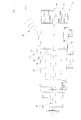
- a machine tool provided with an electric spindle 2, which has a given longitudinal axis 3, is made to advance in a known way in three directions substantially orthogonal to one another according to the machining operations to be carried out and the dimensions and shapes of the articles to be machined, and comprises a containment body 4, which extends around the axis 3 and houses inside an electric motor 5 provided with an output shaft 6 on which a tool (known and not illustrated) can be fitted.
- the tool (not illustrated) is clamped on the shaft 6 via a coupling device (known and not illustrated) shaped for imparting on the tool (not illustrated) a rotary motion about the axis 3.
- a coupling device known and not illustrated
- the electric spindle 2 is moreover provided with a detection device 7 comprising, in the case in point, at least one sensor 8 housed inside the body 4 for detecting in real time at least one operating parameter of the electric spindle 2 chosen in the set constituted by: instantaneous or maximum speed of the shaft 6; instantaneous or maximum acceleration of the shaft 6; time of use of the electric spindle 2; instantaneous or maximum temperature of the electric spindle 2; vibrations of the electric spindle 2; electrical current absorbed by the electric spindle 2; acceleration of the electric spindle 2 in the aforesaid three directions of advance; and position of the aforesaid coupling member (not illustrated) along the axis 3 and/or around the axis 3 itself.
- a detection device 7 comprising, in the case in point, at least one sensor 8 housed inside the body 4 for detecting in real time at least one operating parameter of the electric spindle 2 chosen in the set constituted by: instantaneous or maximum speed of the shaft 6;
- the data acquired by the sensor 8 are stored in a memory 9 provided with an interface 10 designed to enable the operator to download the data acquired by the sensor 8 from the memory 9.
- the electric spindle 2 is provided with a display for displaying the operating parameter detected by the sensor 8.
- the machine tool 1 further comprises an electronic control unit 11 connected, in the case in point, to the electric spindle 2 via a transmission device 12, in the case in point a radio-signal transmission device, which can be alternative or auxiliary to the memory 9 and enables transmission of the data acquired by the sensor 8 to the control unit 11 itself.
- a transmission device 12 in the case in point a radio-signal transmission device, which can be alternative or auxiliary to the memory 9 and enables transmission of the data acquired by the sensor 8 to the control unit 11 itself.
- the instantaneous value of the operating parameter detected in real time by the sensor 8 is transmitted to the control unit 11 to enable feedback control by the device 12 of operation of the electric spindle 2 when the instantaneous value detected by the sensor 8 differs from a reference value stored in the control unit 11 and to prevent, for example, overstepping of a given threshold value and, hence, stoppage of the machine 1 for the consequent maintenance operations.
- the presence of the detection device 7 moreover enables the manufacturer of the electric spindle 2 to control operation of the electric spindle 2 and establish with certainty whether the failure of the electric spindle 2 is caused by normal wear deriving from proper use of the electric spindle 2, by an improper use of the electric spindle 2, or by a defect of fabrication of the electric spindle 2 itself.
- the manufacturer of the electric spindle 2 can establish with certainty whether to apply the period of warranty or not.
Landscapes
- Engineering & Computer Science (AREA)
- Mechanical Engineering (AREA)
- Human Computer Interaction (AREA)
- Manufacturing & Machinery (AREA)
- Physics & Mathematics (AREA)
- General Physics & Mathematics (AREA)
- Automation & Control Theory (AREA)
- Machine Tool Sensing Apparatuses (AREA)
- Numerical Control (AREA)
Applications Claiming Priority (1)
| Application Number | Priority Date | Filing Date | Title |
|---|---|---|---|
| ITBO20070355 ITBO20070355A1 (it) | 2007-05-14 | 2007-05-14 | Elettromandrino |
Publications (2)
| Publication Number | Publication Date |
|---|---|
| EP1995018A2 true EP1995018A2 (fr) | 2008-11-26 |
| EP1995018A3 EP1995018A3 (fr) | 2011-08-24 |
Family
ID=39712179
Family Applications (1)
| Application Number | Title | Priority Date | Filing Date |
|---|---|---|---|
| EP08156118A Withdrawn EP1995018A3 (fr) | 2007-05-14 | 2008-05-13 | Axe électrique |
Country Status (2)
| Country | Link |
|---|---|
| EP (1) | EP1995018A3 (fr) |
| IT (1) | ITBO20070355A1 (fr) |
Cited By (3)
| Publication number | Priority date | Publication date | Assignee | Title |
|---|---|---|---|---|
| CN109759898A (zh) * | 2019-03-22 | 2019-05-17 | 陕西宝光真空电器股份有限公司 | 精雕机用电主轴故障测试诊断系统及其诊断方法 |
| WO2020049449A1 (fr) * | 2018-09-03 | 2020-03-12 | Hsd S.P.A. | Dispositif d'actionnement destiné à une machine-outil |
| DE102018007905A1 (de) * | 2018-10-08 | 2020-04-09 | Günther Zimmer | Arbeitsspindel mit Sensoren und Verfahren zur Erfassung und Überwachung ihrer Historie |
Family Cites Families (2)
| Publication number | Priority date | Publication date | Assignee | Title |
|---|---|---|---|---|
| DE10007126B4 (de) * | 2000-02-17 | 2006-06-22 | Paul Müller GmbH & Co. KG Unternehmensbeteiligungen | Spindel mit einem Datenspeicherelement |
| US6808345B2 (en) * | 2001-10-16 | 2004-10-26 | Toshiba Kikai Kabushiki Kaisha | Tool, tool holder, and machine tool |
-
2007
- 2007-05-14 IT ITBO20070355 patent/ITBO20070355A1/it unknown
-
2008
- 2008-05-13 EP EP08156118A patent/EP1995018A3/fr not_active Withdrawn
Cited By (8)
| Publication number | Priority date | Publication date | Assignee | Title |
|---|---|---|---|---|
| WO2020049449A1 (fr) * | 2018-09-03 | 2020-03-12 | Hsd S.P.A. | Dispositif d'actionnement destiné à une machine-outil |
| CN112997124A (zh) * | 2018-09-03 | 2021-06-18 | Hsd 股份有限公司 | 用于机床的操作装置 |
| US11782405B2 (en) | 2018-09-03 | 2023-10-10 | Hsd S.P.A. | Operating device for a machine tool |
| TWI850251B (zh) * | 2018-09-03 | 2024-08-01 | 義大利商Hsd股份公司 | 工具機、用於工具機的操作裝置、以及收集工具機的操作資料的系統及方法 |
| DE102018007905A1 (de) * | 2018-10-08 | 2020-04-09 | Günther Zimmer | Arbeitsspindel mit Sensoren und Verfahren zur Erfassung und Überwachung ihrer Historie |
| EP3636385B1 (fr) | 2018-10-08 | 2023-09-20 | Günther Zimmer | Broche de travail pourvue de capteurs et procédé de détection et de surveillance de son historique |
| CN109759898A (zh) * | 2019-03-22 | 2019-05-17 | 陕西宝光真空电器股份有限公司 | 精雕机用电主轴故障测试诊断系统及其诊断方法 |
| CN109759898B (zh) * | 2019-03-22 | 2024-02-27 | 陕西宝光真空电器股份有限公司 | 精雕机用电主轴故障测试诊断系统及其诊断方法 |
Also Published As
| Publication number | Publication date |
|---|---|
| EP1995018A3 (fr) | 2011-08-24 |
| ITBO20070355A1 (it) | 2008-11-15 |
Similar Documents
| Publication | Publication Date | Title |
|---|---|---|
| US9069347B2 (en) | Machine tool comprising a device for collision monitoring | |
| CN107685315B (zh) | 电动工具 | |
| US9007007B2 (en) | Handheld machine tool | |
| US9289892B2 (en) | Hand-held power tool | |
| RU2588971C2 (ru) | Угловая шлифовальная машина с датчиком скорости вращения для измерения вращения корпуса | |
| US20140216773A1 (en) | Electric machine tool and method for controlling the electric machine tool | |
| US9612595B2 (en) | Chatter vibration suppressing method and machine tool | |
| US20150030405A1 (en) | Control method of machine tool and machine tool | |
| CN111002088B (zh) | 机床 | |
| EP1878535A1 (fr) | Système de capteur pour machines-outils | |
| EP1995018A2 (fr) | Axe électrique | |
| US20010051841A1 (en) | Processing machine with abnormal-load detecting function | |
| JP2016074072A (ja) | 自動工具交換装置を備えた工作機械の制御装置 | |
| CN106452264A (zh) | 电动机控制系统 | |
| CN112743392B (zh) | 机床中的主轴转速的监视装置及监视方法、机床 | |
| KR20180002692A (ko) | 마이크로 윤활 시스템 | |
| WO2019137818A1 (fr) | Outil à entraînement électrique comprenant au moins un actionneur de freinage intelligent, et procédé servant à faire fonctionner un outil | |
| KR20200022423A (ko) | 전동 공구와 전동 공구의 이벤트 및/또는 상태를 식별하기 위한 방법 | |
| US9808919B2 (en) | Handheld screwing apparatus | |
| KR101212880B1 (ko) | 공작기계의 진동 모니터링 시스템 | |
| JPH11170142A (ja) | 主軸異常監視装置 | |
| JP6442223B2 (ja) | 作業機 | |
| KR101314444B1 (ko) | 공작기계의 윤활유 제어 장치 및 그의 구동방법 | |
| CN108942806B (zh) | 手持电动工具及其控制方法、控制装置 | |
| JP6329875B2 (ja) | 作業機用加速度検出システム |
Legal Events
| Date | Code | Title | Description |
|---|---|---|---|
| PUAI | Public reference made under article 153(3) epc to a published international application that has entered the european phase |
Free format text: ORIGINAL CODE: 0009012 |
|
| AK | Designated contracting states |
Kind code of ref document: A2 Designated state(s): AT BE BG CH CY CZ DE DK EE ES FI FR GB GR HR HU IE IS IT LI LT LU LV MC MT NL NO PL PT RO SE SI SK TR |
|
| AX | Request for extension of the european patent |
Extension state: AL BA MK RS |
|
| PUAL | Search report despatched |
Free format text: ORIGINAL CODE: 0009013 |
|
| AK | Designated contracting states |
Kind code of ref document: A3 Designated state(s): AT BE BG CH CY CZ DE DK EE ES FI FR GB GR HR HU IE IS IT LI LT LU LV MC MT NL NO PL PT RO SE SI SK TR |
|
| AX | Request for extension of the european patent |
Extension state: AL BA MK RS |
|
| RIC1 | Information provided on ipc code assigned before grant |
Ipc: B23Q 5/10 20060101ALI20110721BHEP Ipc: G05D 27/00 20060101ALI20110721BHEP Ipc: B23Q 15/00 20060101AFI20110721BHEP |
|
| AKY | No designation fees paid | ||
| REG | Reference to a national code |
Ref country code: DE Ref legal event code: R108 Effective date: 20120502 |
|
| STAA | Information on the status of an ep patent application or granted ep patent |
Free format text: STATUS: THE APPLICATION IS DEEMED TO BE WITHDRAWN |
|
| 18D | Application deemed to be withdrawn |
Effective date: 20120225 |