EP1995019A2 - Défonceuse - Google Patents
Défonceuse Download PDFInfo
- Publication number
- EP1995019A2 EP1995019A2 EP08004316A EP08004316A EP1995019A2 EP 1995019 A2 EP1995019 A2 EP 1995019A2 EP 08004316 A EP08004316 A EP 08004316A EP 08004316 A EP08004316 A EP 08004316A EP 1995019 A2 EP1995019 A2 EP 1995019A2
- Authority
- EP
- European Patent Office
- Prior art keywords
- stop
- clamping
- support table
- router according
- clamping element
- Prior art date
- Legal status (The legal status is an assumption and is not a legal conclusion. Google has not performed a legal analysis and makes no representation as to the accuracy of the status listed.)
- Granted
Links
- 238000003801 milling Methods 0.000 claims abstract description 65
- 230000000630 rising effect Effects 0.000 claims description 2
- 230000002093 peripheral effect Effects 0.000 description 2
- 238000000034 method Methods 0.000 description 1
- 230000007704 transition Effects 0.000 description 1
Images



Classifications
-
- B—PERFORMING OPERATIONS; TRANSPORTING
- B27—WORKING OR PRESERVING WOOD OR SIMILAR MATERIAL; NAILING OR STAPLING MACHINES IN GENERAL
- B27C—PLANING, DRILLING, MILLING, TURNING OR UNIVERSAL MACHINES FOR WOOD OR SIMILAR MATERIAL
- B27C5/00—Machines designed for producing special profiles or shaped work, e.g. by rotary cutters; Equipment therefor
- B27C5/10—Portable hand-operated wood-milling machines; Routers
Definitions
- the invention relates to a router with a Kirfan monocyte on a workpiece, a Jerusalem Bachsaus fundamentalung having support table, stand up from the guide columns on which a milling head with a drive unit for a downwardly projecting, milling the cross-recess cross-cutting tool guided in column longitudinal direction and displaceable in the longitudinal direction respective longitudinal position can be determined, wherein the milling head is arranged parallel to the columns, adjustable by means of a fine adjustment in its longitudinal position relative to the milling head stop rod, which is clamped by a clamping element with a stop element arranged on a movable on the top of the support table stop carrier is.
- the milling depth must be set as accurately as possible. This applies, for example, when milling a workpiece edge, which should be rounded off and pass without offset into the workpiece surface.
- the stop carrier is rotatably mounted on the support table and has even more stop elements, which can be rotated with non-braced stop rod under respective latching the stop carrier with the support table below the stop bar and other milling work, in which the milling head performs a milling movement in the column longitudinal direction, serve as a depth stop.
- the rotatable and latching mounting of the stop carrier inevitably brings a certain amount of play between the stop carrier and the support table with it.
- the resulting work result is not always satisfactory and may be subject to a tolerance in the extent of existing between the stop carrier and the support table game.
- the resulting inaccuracy depends on the forces acting on the milling head parallel to the column longitudinal direction. These are in particular the spring force applied to the milling head in the usual routers in the direction away from the support table and the force exerted by the user when holding the router to the support table. The resultant of these forces acts on the stop carrier, which can move in the extent of said game, so that the mentioned tolerances can result.
- the present invention is therefore an object of the invention to provide a router of the type mentioned, with the possible tolerance-free adjustment of the milling depth is possible.
- clamping element during clamping on the one hand acts on the stop rod to the stop element out and on the other hand supported in the opposite direction to a clearance on the support table arranged abutment element.
- the stop bar remains free of play relative to the support table regardless of the forces occurring in place, so that the desired depth of cut can be adjusted by means of fine adjustment and permanently maintained unchanged. This applies regardless of whether the milling head is moved toward or away from the support table during the fine adjustment.
- the abutment element is formed by a radial projection which protrudes in the radial direction of a play-free arranged on the support table holding part.
- the holding part is expediently one of the support table upstanding retaining bolt and the abutment member formed by a head piece of the retaining bolt.
- the retaining bolt is preferably screwed into the support table.
- the retaining bolt forms a bearing axis for the stop carrier rotatably mounted on the support table.
- the clamping element can be rotatably mounted about an axis of rotation parallel to the longitudinal direction of the column and have a clamping surface which points in the direction of the axis of rotation and which rises in the circumferential direction.
- the clamping element is mounted rotatably supported on the stop rod and supported in the axial direction to the support table, wherein the clamping surface is arranged on the upper side of the clamping element facing away from the support table and engages under the abutment element during clamping.
- the clamping element is rotatably mounted on the retaining bolt and supported in the axial direction away from the support table against the abutment element, wherein the clamping surface is arranged on the support table facing the underside of the clamping element and engages over a loading surface on the stop rod during bracing.
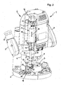
- a hand tool in the form of a router 1 shows that in a usual manner on a milled workpiece (not shown) auf complexityden support table 2 with a für Stammsaus principleung 3, two from the support table 2 at a distance parallel to each other upstanding guide columns 4, 5 and a has on the guide columns 4, 5 slidably guided and lockable in the respective longitudinal position milling head.
- the milling head 6 includes a motor drive unit for rotatably driving a mounted on the support table 2 facing bottom of the milling head 6 interchangeable, in FIG. 1 dash-dotted lines indicated milling tool 29 which protrudes from the milling head 6 downwards and passes through the through-passage 3 of the support table 2 to the workpiece during milling.
- two lateral handles 7, 8 are arranged, where the milling head can be taken.
- the handle 7, a knob 9 is arranged, with which the milling head 6 fixed to the guide columns 4, 5 and can be solved by the guide columns 4, 5.
- the rotary knob 9 is connected via a arranged in the interior of the handle 7 deflection gear with a cooperating with the guide columns 4, 5 clamping device, as for example in the DE 201 18 117 U1 is described.
- the milling head 6 is clamped to the guide columns 4, 5 or the clamping is canceled, so that the milling head 6 can be moved.
- a stop rod 10 is further arranged, which extends parallel to the guide columns 4, 5.
- the stop rod 10 is adjustable by means of a fine adjustment 11 in its longitudinal position relative to the milling head 6.
- the stop bar 10 in the embodiment of two parts (in principle, it could also be one piece) and consists of a connected to the milling head 6 via the fine adjustment 11 upper bar section 12 and a telescopically extendable and retractable connected to the upper bar section 12 lower rod section 13, the 2 facing the support table.
- the lower rod section 13 can be fixed in its respective longitudinal position by means of a rotary handle 14, for example in the form of a clamping lever on the upper rod section 12.
- a rotary handle 14 When turning the rotary handle 14 in the clamping direction, a non-rotatably connected with her threaded shank screws in the wall of the upper rod section 12 against the lower rod section 13, so that the two rod sections 12, 13 are clamped together.
- the clamping screw moves away from the lower rod section 13, so that it can be moved.
- the upper rod section 12 dives from below into the milling head 6 and expediently into a lateral housing extension 15 of the milling head 6. Its longitudinal position relative to the milling head 6 can be adjusted by means of the fine adjustment device 11 already mentioned.
- the adjustment to the support table 2 out (down) or away from the support table 2 (upward) by twisting in one or the other direction of a rotatably mounted on the milling head, expediently arranged in the embodiment of the lower rod section 13 upper end of the housing extension 15, knob-like rotary member 16 which is fixedly connected in the longitudinal direction 18 with the milling head 6.
- the fine adjustment device 11 may for example contain a spindle drive. An example of such a spindle drive is in FIG. 2 indicated by dashed lines.
- He has a rotatably connected to the rotary member 16 threaded spindle 17, which is in threaded engagement with the upper rod section 12.
- the upper rod section 12 is rotatably mounted so that it is displaced parallel to the column longitudinal direction 18 during rotation of the rotary member 16.
- a stop support 19 is arranged, which is rotatably mounted about a parallel to the guide columns 4, 5 bearing axis 20.
- a plurality of spaced about the bearing axis 20 around stop elements 21, 22, 23 are arranged, which stand at different heights.
- the stop carrier 19 is locked to the support table 2, for example, by means of a planer toothing and under the action of a spring arrangement 26 provided between the stop carrier 19 and the support table 2.
- stop elements 22, 23 are screwed in upstanding sleeves 24, 25 of the stop member 19 screws so that the stop elements 22, 23 can be adjusted in height.
- the stop element 21, however, is not adjustable fixedly arranged on the stop carrier 19.
- the stop elements 21, 22, 23 can be used as selectively interacting with the stop bar 10 depth stops, if you want to move the milling head 6 to a desired depth of cut down.
- the stop bar 10 is preset in its longitudinal position so that it only hits the respective stop element 21, 22, 23 at the desired cutting depth. This setting of the stop bar 10 takes place by appropriately setting the lower bar section 13 on the upper bar section 12.
- the present case is concerned that the milling head 6 is fixed before milling at a certain distance from the support table 2.
- the workpiece edge has a special profile, for example a profile with a curve that merges into the workpiece surface, then the correspondingly shaped milling tool must be positioned as precisely as possible so that no shoulder occurs at the transition of the rounding into the workpiece surface. Therefore, the distance between the milling head and thus the milling head tool on the one hand and the support table 2 on the other hand must be able to be set very accurately. This is practically impossible with the described clamping of the milling head 6 on the guide columns 4, 5. Hereby, only a coarse adjustment of the milling depth can be achieved.
- the stop bar 10 with one of the stop elements, with the immutable stop element 21 (in principle, it could also be another stop element) is firmly clamped by a clamping element 27 during clamping on the one hand the stop rod 10 to the stop member 21 down and on the other hand in the opposite direction, ie away in the direction of the support table, in a longitudinal direction 18th play free on the support table 2 arranged abutment element 28 is supported.
- the stop bar 10 is not only pressed firmly against the stop element 21 but also the stop element 21 and with this the stop carrier 19 firmly against the support table 2, so that play-free conditions are present.
- the procedure is such that the milling depth is initially roughly adjusted by displacing the milling head 6 when the milling head 6 permits rotating position of the rotary knob 6 so far that the milling tool 29 is approximately at the correct height. Then, the milling head 6 is fixed by means of the rotary knob 9 to the guide columns 4, 5 and the lower rod portion 13 of the stop bar 10 is lowered onto the stop element 21 ( FIG. 2 ). For this purpose, the rotary handle 14 is rotated accordingly, so that the lower rod section 13 can be moved relative to the upper rod section 12. Subsequently, one brings the clamping element 27 in its clamping position ( FIG.
- a length scale 30 may be arranged on the outside of the milling head 6, which is assigned a read-out pointer 31 in the longitudinal direction of a holding rod 33 connected to its lower end via a connecting member 32 fixed to the stop bar 10 and thereby with its lower bar section 13 18 is slidably mounted and lockable.
- the abutment element 28 is expediently formed by a radial projection 34 which projects in the radial direction from a holding part 35 arranged without play on the support table 2.
- the holding part 35 can be formed by a support pin 36 standing up from the support table 2 and the abutment element 28 by a head piece 37 of the retaining bolt 36.
- the retaining bolt 36 is suitably screwed fixed in the support table 2.
- the retaining bolt 36 is used as a bearing axis 20 for the rotatably mounted on the support table 2 stop support 19.
- the stop carrier 19 accordingly has a through-hole 38 penetrated by the retaining bolt 36.
- a stop carrier 19 is arranged with a rotational play against the support table 2 retaining collar 39 which can be formed for example by a bearing ring.
- the clamping element 27 is rotatably mounted about an axis parallel to the longitudinal axis 18 axis of rotation, which in the case of the embodiment of the FIGS. 1 to 5 from the stop bar 10 and in the case of the alternative embodiment FIG. 6 is formed by the retaining bolt 36.
- the clamping element 27 thus on the stop bar 10 and thereby on the lower rod section 13 and in the case of the embodiment according to FIG. 6 rotatably mounted on the retaining bolt 36.
- the clamping element 27 is supported in both cases to the support table 2 out.
- a fixed support ring 40 is arranged at the bottom of the stop bar 10, via which the clamping element 27 transmits the clamping force on the stop rod 10 during clamping.
- FIG. 6 is on the retaining pin 36 below the clamping element 27, a retaining ring 41 is arranged, which holds the clamping element 27 in height.
- the clamping element 27 has an in the axial direction of the stop rod 10 and the retaining pin 36 formed axis of rotation facing, rising in the circumferential direction clamping surface 42.
- the clamping surface 42 is arranged on the upper side of the clamping element 27 facing away from the support table 2 and engages under tensioning the abutment element 28, which is formed here by the head piece 37 of the retaining bolt 36.
- FIG. 6 is the clamping surface 42 disposed on the support table 2 facing the underside of the clamping element 27 and engages during clamping a arranged on the stop bar 10 Beaufschlagungs makeup 43.
- the respective clamping element 27 has a sleeve-shaped bearing portion 45, with which the clamping element 27 is rotatably mounted on the stop bar 10 and on the retaining bolt 36.
- the respective Clamping element 27 further has a clamping part 46 which is arranged on the outside of the sleeve-shaped bearing part 45 and forms the clamping surface 42. The tensioning part 46 projects radially outward from the bearing part 45.
- the arrangement is expediently made such that the tensioning part 46 extends over a smaller circumferential angle than 360 °, so that the tensioning element 27 has a peripheral region 47 which is free of the tensioning part 46.
- the free peripheral region 47 is so large that the clamping element 27, it is mounted on the stop bar 10, the abutment member 28 and, if it is mounted on the retaining pin 36, the stop rod 10 can be moved past. This is necessary so that you can lower the previously arranged above holding rod 10 on the stop element 21.
- the clamping element 27 has a protruding from him handle 48, where the user can take the clamping element 27 to rotate.
- associated stop member 21 may have a centering mandrel 49 on its upper side facing the stop bar 10, which is associated with a corresponding centering on the stop bar 10. In this way, the stop bar 10 is exactly centered during clamping.
- FIGS. 1 and 3 show with respect to the embodiment of the FIGS. 1 to 5 the situation in which the stop bar 10 is lowered onto the stop element 21, the tensioning element 27, however, still occupies its release position remote from the abutment element 28.
- the tensioning element 27 Upon rotation of the clamping element 27 whose clamping surface 42 passes under the abutment member 28, such as FIG. 4 shows.
- FIG. 6 shows the local clamping element 27 in its release position. If the local tensioning element 27 is twisted, its tensioning part 46 passes into the engagement recess 44 of the stopper rod 10 and presses against its loading surface 43. The tensioning element 27 is supported on the abutment element 28 formed by the head piece 37 of the retaining bolt 36.
Landscapes
- Life Sciences & Earth Sciences (AREA)
- Engineering & Computer Science (AREA)
- Mechanical Engineering (AREA)
- Wood Science & Technology (AREA)
- Forests & Forestry (AREA)
- Milling, Drilling, And Turning Of Wood (AREA)
Applications Claiming Priority (1)
| Application Number | Priority Date | Filing Date | Title |
|---|---|---|---|
| DE200710023783 DE102007023783B3 (de) | 2007-05-22 | 2007-05-22 | Oberfräse |
Publications (3)
| Publication Number | Publication Date |
|---|---|
| EP1995019A2 true EP1995019A2 (fr) | 2008-11-26 |
| EP1995019A3 EP1995019A3 (fr) | 2013-06-12 |
| EP1995019B1 EP1995019B1 (fr) | 2014-01-15 |
Family
ID=39531110
Family Applications (1)
| Application Number | Title | Priority Date | Filing Date |
|---|---|---|---|
| EP20080004316 Active EP1995019B1 (fr) | 2007-05-22 | 2008-03-08 | Défonceuse |
Country Status (2)
| Country | Link |
|---|---|
| EP (1) | EP1995019B1 (fr) |
| DE (1) | DE102007023783B3 (fr) |
Citations (2)
| Publication number | Priority date | Publication date | Assignee | Title |
|---|---|---|---|---|
| DE3347764A1 (de) | 1983-04-21 | 1985-02-28 | Festo-Maschinenfabrik Gottlieb Stoll, 7300 Esslingen | Oberfraese |
| DE20118117U1 (de) | 2001-11-07 | 2002-01-10 | Festool GmbH, 73240 Wendlingen | Werkzeugmaschine mit zwei Säulen und einer Feststelleinrichtung |
Family Cites Families (4)
| Publication number | Priority date | Publication date | Assignee | Title |
|---|---|---|---|---|
| DE1770357U (de) * | 1957-06-18 | 1958-07-17 | Rudolf Nitzsche | Fraestiefen-feststelleinrichtung fuer elektrische handfraesmaschinen. |
| DE7415327U (de) * | 1974-05-02 | 1974-08-01 | Lutz E Kg | Vorrichtung zur Schnittiefeneinstellung von Hand-Oberfräsen |
| DE3314419C2 (de) * | 1983-04-21 | 1985-09-12 | Festo-Maschinenfabrik Gottlieb Stoll, 7300 Esslingen | Oberfräse mit Staubabsaugung |
| US6488455B1 (en) * | 2000-07-28 | 2002-12-03 | S-B Power Tool Company | Plunge base router |
-
2007
- 2007-05-22 DE DE200710023783 patent/DE102007023783B3/de not_active Expired - Fee Related
-
2008
- 2008-03-08 EP EP20080004316 patent/EP1995019B1/fr active Active
Patent Citations (2)
| Publication number | Priority date | Publication date | Assignee | Title |
|---|---|---|---|---|
| DE3347764A1 (de) | 1983-04-21 | 1985-02-28 | Festo-Maschinenfabrik Gottlieb Stoll, 7300 Esslingen | Oberfraese |
| DE20118117U1 (de) | 2001-11-07 | 2002-01-10 | Festool GmbH, 73240 Wendlingen | Werkzeugmaschine mit zwei Säulen und einer Feststelleinrichtung |
Also Published As
| Publication number | Publication date |
|---|---|
| EP1995019A3 (fr) | 2013-06-12 |
| DE102007023783B3 (de) | 2008-07-24 |
| EP1995019B1 (fr) | 2014-01-15 |
Similar Documents
| Publication | Publication Date | Title |
|---|---|---|
| DE3824200C1 (fr) | ||
| DE2167082B1 (de) | Bohrkopf mit einer Vorrichtung zum Verschieben mindestens eines Schneideinsatzes in einem drehbaren Schneidwerkzeugtraeger | |
| EP3311693A1 (fr) | Châssis réglable en hauteur comprenant des éléments de jambage rabattables | |
| DE19949743C1 (de) | Zerspanungs-Werkzeug für die Hochgeschwindigkeitsbearbeitung | |
| DE20301042U1 (de) | Bohrständer | |
| WO2019179789A1 (fr) | Adaptateur de fraisage pour une table de travail | |
| DE102010042951B4 (de) | Bearbeitungsmaschine in Ständerbauart, insbesondere Ständerbohrmaschine | |
| DE102013210951A1 (de) | Bearbeitungsmaschine in Ständerbauart | |
| DE3736757C1 (de) | Tischfraeseinrichtung | |
| EP0824998B1 (fr) | Outil pour la manutention d'une machine-outil | |
| EP1995019B1 (fr) | Défonceuse | |
| DE3606795A1 (de) | Vorrichtung zum verstellen eines werkstueckanschlags oder dergleichen fuer eine holzbearbeitungsmaschine | |
| DE3040651C2 (de) | Arbeitsständer für Bohrmaschinen | |
| WO1999002292A1 (fr) | Ensemble de scie d'entree avec dispositif d'ejection | |
| DE2910642C2 (de) | Vorrichtung zum Ausschneiden kreisförmiger Werkstücke | |
| DE102004035263B3 (de) | Werkzeughalter einer Werkzeugmaschine | |
| DE4016012C2 (fr) | ||
| DE874549C (de) | Vorrichtung fuer die Herstellung von regelmaessigen Vielkanten, z. B. von vielkantigen Loechern oder Zapfen | |
| DE29717694U1 (de) | Lochsägeeinrichtung mit Auswerfereinrichtung | |
| DE3316364A1 (de) | Vorrichtung zum sichern des stoessels einer werkzeugmaschine, insbesondere einer grosspresse | |
| AT165334B (de) | Vorrichtung zur Herstellung von regelmäßigen Vielkanten z. B. von vielkantigen Löchern oder Zapfen | |
| DE102004015697B4 (de) | Messvorrichtung | |
| DE941646C (de) | Einrichtung fuer einen auf dem Schlitten einer Werkzeugmaschine verschiebbaren Tisch | |
| DD145607A1 (de) | Bohrstaender mit einem elektro-haftmagneten | |
| DE9014066U1 (de) | Schraubstock |
Legal Events
| Date | Code | Title | Description |
|---|---|---|---|
| PUAI | Public reference made under article 153(3) epc to a published international application that has entered the european phase |
Free format text: ORIGINAL CODE: 0009012 |
|
| AK | Designated contracting states |
Kind code of ref document: A2 Designated state(s): AT BE BG CH CY CZ DE DK EE ES FI FR GB GR HR HU IE IS IT LI LT LU LV MC MT NL NO PL PT RO SE SI SK TR |
|
| AX | Request for extension of the european patent |
Extension state: AL BA MK RS |
|
| RAP1 | Party data changed (applicant data changed or rights of an application transferred) |
Owner name: FESTOOL GROUP GMBH & CO. KG |
|
| PUAL | Search report despatched |
Free format text: ORIGINAL CODE: 0009013 |
|
| AK | Designated contracting states |
Kind code of ref document: A3 Designated state(s): AT BE BG CH CY CZ DE DK EE ES FI FR GB GR HR HU IE IS IT LI LT LU LV MC MT NL NO PL PT RO SE SI SK TR |
|
| AX | Request for extension of the european patent |
Extension state: AL BA MK RS |
|
| RIC1 | Information provided on ipc code assigned before grant |
Ipc: B27C 5/10 20060101ALI20130508BHEP Ipc: B23Q 16/00 20060101AFI20130508BHEP |
|
| GRAP | Despatch of communication of intention to grant a patent |
Free format text: ORIGINAL CODE: EPIDOSNIGR1 |
|
| 17P | Request for examination filed |
Effective date: 20130608 |
|
| RBV | Designated contracting states (corrected) |
Designated state(s): AT BE BG CH CY CZ DE DK EE ES FI FR GB GR HR HU IE IS IT LI LT LU LV MC MT NL NO PL PT RO SE SI SK TR |
|
| INTG | Intention to grant announced |
Effective date: 20130719 |
|
| GRAS | Grant fee paid |
Free format text: ORIGINAL CODE: EPIDOSNIGR3 |
|
| GRAA | (expected) grant |
Free format text: ORIGINAL CODE: 0009210 |
|
| AK | Designated contracting states |
Kind code of ref document: B1 Designated state(s): DE FR GB |
|
| REG | Reference to a national code |
Ref country code: GB Ref legal event code: FG4D Free format text: NOT ENGLISH |
|
| AKX | Designation fees paid |
Designated state(s): DE FR GB |
|
| REG | Reference to a national code |
Ref country code: DE Ref legal event code: R096 Ref document number: 502008011217 Country of ref document: DE Effective date: 20140227 |
|
| REG | Reference to a national code |
Ref country code: DE Ref legal event code: R082 Ref document number: 502008011217 Country of ref document: DE Representative=s name: BREGENZER, MICHAEL, DIPL.-ING., DE |
|
| RAP2 | Party data changed (patent owner data changed or rights of a patent transferred) |
Owner name: FESTOOL GMBH |
|
| REG | Reference to a national code |
Ref country code: DE Ref legal event code: R097 Ref document number: 502008011217 Country of ref document: DE |
|
| REG | Reference to a national code |
Ref country code: DE Ref legal event code: R082 Ref document number: 502008011217 Country of ref document: DE Representative=s name: BREGENZER, MICHAEL, DIPL.-ING., DE Effective date: 20140918 Ref country code: DE Ref legal event code: R081 Ref document number: 502008011217 Country of ref document: DE Owner name: FESTOOL GMBH, DE Free format text: FORMER OWNER: FESTOOL GROUP GMBH & CO. KG, 73240 WENDLINGEN, DE Effective date: 20140918 Ref country code: DE Ref legal event code: R082 Ref document number: 502008011217 Country of ref document: DE Representative=s name: PATENTANWAELTE BREGENZER UND REULE PARTNERSCHA, DE Effective date: 20140918 |
|
| PLBE | No opposition filed within time limit |
Free format text: ORIGINAL CODE: 0009261 |
|
| STAA | Information on the status of an ep patent application or granted ep patent |
Free format text: STATUS: NO OPPOSITION FILED WITHIN TIME LIMIT |
|
| REG | Reference to a national code |
Ref country code: DE Ref legal event code: R082 Ref document number: 502008011217 Country of ref document: DE Representative=s name: PATENTANWAELTE BREGENZER UND REULE PARTNERSCHA, DE |
|
| 26N | No opposition filed |
Effective date: 20141016 |
|
| REG | Reference to a national code |
Ref country code: DE Ref legal event code: R097 Ref document number: 502008011217 Country of ref document: DE Effective date: 20141016 |
|
| REG | Reference to a national code |
Ref country code: FR Ref legal event code: PLFP Year of fee payment: 9 |
|
| REG | Reference to a national code |
Ref country code: FR Ref legal event code: PLFP Year of fee payment: 10 |
|
| REG | Reference to a national code |
Ref country code: FR Ref legal event code: PLFP Year of fee payment: 11 |
|
| P01 | Opt-out of the competence of the unified patent court (upc) registered |
Effective date: 20230517 |
|
| PGFP | Annual fee paid to national office [announced via postgrant information from national office to epo] |
Ref country code: DE Payment date: 20250212 Year of fee payment: 18 |
|
| PGFP | Annual fee paid to national office [announced via postgrant information from national office to epo] |
Ref country code: FR Payment date: 20250218 Year of fee payment: 18 |
|
| PGFP | Annual fee paid to national office [announced via postgrant information from national office to epo] |
Ref country code: GB Payment date: 20250218 Year of fee payment: 18 |