EP1995072A2 - Bildgebendes Gerät mit einem Element zur Detektion fehlender Düsen - Google Patents
Bildgebendes Gerät mit einem Element zur Detektion fehlender Düsen Download PDFInfo
- Publication number
- EP1995072A2 EP1995072A2 EP08100670A EP08100670A EP1995072A2 EP 1995072 A2 EP1995072 A2 EP 1995072A2 EP 08100670 A EP08100670 A EP 08100670A EP 08100670 A EP08100670 A EP 08100670A EP 1995072 A2 EP1995072 A2 EP 1995072A2
- Authority
- EP
- European Patent Office
- Prior art keywords
- image
- image forming
- unit
- print medium
- path
- Prior art date
- Legal status (The legal status is an assumption and is not a legal conclusion. Google has not performed a legal analysis and makes no representation as to the accuracy of the status listed.)
- Withdrawn
Links
Images



Classifications
-
- B—PERFORMING OPERATIONS; TRANSPORTING
- B41—PRINTING; LINING MACHINES; TYPEWRITERS; STAMPS
- B41J—TYPEWRITERS; SELECTIVE PRINTING MECHANISMS, i.e. MECHANISMS PRINTING OTHERWISE THAN FROM A FORME; CORRECTION OF TYPOGRAPHICAL ERRORS
- B41J13/00—Devices or arrangements of selective printing mechanisms, e.g. ink-jet printers or thermal printers, specially adapted for supporting or handling copy material in short lengths, e.g. sheets
- B41J13/0009—Devices or arrangements of selective printing mechanisms, e.g. ink-jet printers or thermal printers, specially adapted for supporting or handling copy material in short lengths, e.g. sheets control of the transport of the copy material
- B41J13/0045—Devices or arrangements of selective printing mechanisms, e.g. ink-jet printers or thermal printers, specially adapted for supporting or handling copy material in short lengths, e.g. sheets control of the transport of the copy material concerning sheet refeed sections of automatic paper handling systems, e.g. intermediate stackers
-
- B—PERFORMING OPERATIONS; TRANSPORTING
- B41—PRINTING; LINING MACHINES; TYPEWRITERS; STAMPS
- B41J—TYPEWRITERS; SELECTIVE PRINTING MECHANISMS, i.e. MECHANISMS PRINTING OTHERWISE THAN FROM A FORME; CORRECTION OF TYPOGRAPHICAL ERRORS
- B41J11/00—Devices or arrangements of selective printing mechanisms, e.g. ink-jet printers or thermal printers, for supporting or handling copy material in sheet or web form
- B41J11/0045—Guides for printing material
-
- B—PERFORMING OPERATIONS; TRANSPORTING
- B41—PRINTING; LINING MACHINES; TYPEWRITERS; STAMPS
- B41J—TYPEWRITERS; SELECTIVE PRINTING MECHANISMS, i.e. MECHANISMS PRINTING OTHERWISE THAN FROM A FORME; CORRECTION OF TYPOGRAPHICAL ERRORS
- B41J2/00—Typewriters or selective printing mechanisms characterised by the printing or marking process for which they are designed
- B41J2/005—Typewriters or selective printing mechanisms characterised by the printing or marking process for which they are designed characterised by bringing liquid or particles selectively into contact with a printing material
- B41J2/01—Ink jet
- B41J2/21—Ink jet for multi-colour printing
- B41J2/2132—Print quality control characterised by dot disposition, e.g. for reducing white stripes or banding
- B41J2/2142—Detection of malfunctioning nozzles
-
- B—PERFORMING OPERATIONS; TRANSPORTING
- B41—PRINTING; LINING MACHINES; TYPEWRITERS; STAMPS
- B41J—TYPEWRITERS; SELECTIVE PRINTING MECHANISMS, i.e. MECHANISMS PRINTING OTHERWISE THAN FROM A FORME; CORRECTION OF TYPOGRAPHICAL ERRORS
- B41J29/00—Details of, or accessories for, typewriters or selective printing mechanisms not otherwise provided for
- B41J29/38—Drives, motors, controls or automatic cut-off devices for the entire printing mechanism
- B41J29/393—Devices for controlling or analysing the entire machine ; Controlling or analysing mechanical parameters involving printing of test patterns
Definitions
- the present invention relates to an image forming apparatus comprising an image forming unit configured to form a test image on a print medium according to data corresponding to a desired image, and an image scanning unit having a scanning unit to scan documents including the print medium.
- an inkjet image forming apparatus forms images on a print medium by ejecting ink from a printhead which moves backward and forward in a direction perpendicular to a moving direction of a print medium, that is, in the width direction of the print medium.
- a printhead is generally referred to as a shuttle type printhead.
- an array inkjet printhead having a nozzle unit with a length corresponding to the width of a print medium has been suggested instead of the printhead that moves backward and forward in the width direction of the print medium.
- an array inkjet printhead is fixed and only the print medium moves. Accordingly, a driving device that drives the inkjet printhead of the inkjet image forming apparatus is simple and high speed printing can be realized.
- the array inkjet printhead is fixed and has a size corresponding to the width of the print medium, if there is a defect in a nozzle of the fixed printhead, a portion of an image corresponding to the nozzle including the defect cannot be formed.
- the image forming apparatus is automatically corrected or the nozzle including the defect is changed with another neighboring nozzle.
- the inkjet image forming apparatus including the array inkjet printhead needs to have a missing nozzle detection unit to detect nozzles including defects.
- the present invention is characterised by a conveying means disposed between the image forming unit and the image scanning unit to feed the print medium from the image forming unit to the image scanning unit to scan the test image from the print medium to detect defects in the image forming unit.
- an image forming apparatus including an image forming unit formed above a printing path along which an image is formed on a print medium, including a plurality of nozzles to eject ink, an image scanning unit formed adjacent the image forming unit and having a scanning unit formed on a document reading path transferring the document to read the document, and a missing nozzle detection unit including a missing nozzle detection path that connects the printing path and the document reading path, and transports a print medium, on which a test image is formed by the image forming unit, to the document reading path via the missing nozzle detection path to scan the test image using the image scanning unit, wherein the image scanning unit and the missing nozzle detection unit share the scanning unit.
- the image forming unit includes a plurality of nozzles to eject ink to form the test image, and the scanning of the test image detects whether one or more of the nozzles is defective.
- the conveying means includes guide members defining a feed path for the print medium to be fed from the image forming unit to the image scanning unit.
- the conveying means includes a plurality of feed rollers to feed the print medium along the feed path.
- the image forming apparatus may further include a controlling unit to compare the test image with the data corresponding to the desired image to detect whether one or more of the plurality of nozzles is defective.
- the controlling unit may further be configured to perform a correction operation to the or each corresponding defective nozzle.
- the image forming apparatus may further include a rotatable guide unit and rotatable first and second transporting rollers to guide the print medium toward the plurality of nozzles in a first direction to form a test image thereon.
- the second transporting roller and the guide unit may be configured to rotate in a second direction to guide the print medium with the test image formed thereon in a second direction towards a feed path of the conveying means.
- the second transporting roller may further align the print medium according to the feed path to transport the print medium along the feed path.
- the image scanning unit may include a first group of transporting rollers to transport documents along a document reading path to be scanned by the scanning unit.
- the first group of transporting rollers may be formed along the document reading path. Additionally, the first group of transporting rollers and the feed rollers may be simultaneously actuated by a driving source.
- a first end of the feed path may connect to the document reading path and a second end of the feed path may be disposed near the guide unit.
- the image scanning unit may further include a glass panel disposed above the scanning unit and a pressing unit disposed above the glass panel. Additionally, the first group of transporting rollers may transport the plurality of documents one by one onto the glass panel and accordingly the pressing unit secures each of the documents to the glass panel when the document is scanned by the scanning unit.
- the first group of transporting rollers may be meshed with a driving gear and the driving gear may be meshed with the driving source via a first intermediate gear.
- the feed rollers may be meshed with the driving gear and the driving gear may be meshed with the driving source via a second intermediate gear.
- the first group of transporting rollers may be rotated to transport the one or more documents along the document reading path, and the feed rollers may be rotated to transport the print medium with a test image formed thereon along the feed path.
- the present invention also provides a method of deleting a defect in an image forming apparatus having an image forming unit, and an image scanning unit, comprising the steps of the image forming unit forming a test image on a print medium according to data corresponding to a desired image, conveying the print medium to the image scanning unit via conveying means, scanning the test image using the image scanning unit and comparing the scanned test image with data corresponding to a desired image to determine whether the image forming unit is defective.
- the image forming unit comprises a plurality of nozzles to eject ink and the step of determining whether the image forming unit is defective comprises determining whether one or more of the nozzles is defective.
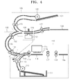
- the multi-functional peripheral device 100 includes an image printing unit 110 to print images, an image scanning unit 120 which is formed above the image printing unit 110 to read documents, and a missing nozzle detection unit 130 which is formed between the image printing unit 110 and the image scanning unit 120 and which scans a print medium on which test images are formed.
- the image printing unit 110 forms an image on a print medium P, and includes a cassette 111, a plurality of transporting rollers 113 and 114, an array inkjet printhead 115 having a plurality of nozzles 115a, a fusing unit 117, and a discharge roller 118 all being located sequentially (i.e. consecutively) along a printing path S1.
- the cassette 111 loads a plurality of print media P, and a pickup roller 112 which picks up the print media P sheet by sheet, is installed above the cassette 111.
- the transporting rollers 113 and 114 transport the print medium P that is picked up by the pickup roller 112 along the printing path S1 and guide the print medium P toward the array inkjet printhead 115.
- the transporting roller 114 may further have a registration function of aligning the print medium P with respect to the printing path S1, prior to transporting the print medium P along the printing path S1.
- the registration function of the transporting roller 114 may preferably rotate the print medium P clockwise or counter clockwise in order to successfully transport the print medium P on which the test image T is printed toward a missing nozzle detection path S3 of the missing nozzle detection unit 130, which will be described in further detail below.
- the array inkjet printhead 115 has a length corresponding to the width of the print medium P, and includes a plurality of nozzles 115a to eject ink.
- a supporting plate 116 to support the print medium P is formed below the array inkjet printhead 115.
- the array inkjet printhead 115 is fixed, and as the print medium P passes below the array inkjet printhead 115, an image is formed on the print medium P by the ink ejected from the plurality of nozzles 115a.
- the fusing unit 117 fuses (i.e. fixes) an image formed by the plurality of nozzles to the print medium P by applying heat and pressure to the image.
- the fusing unit 117 includes a heating roller and a pressurizing roller facing that contact each other, and as the print medium P passes from the array inkjet 115 along the printing path S1 through the fusing unit 117, a combination of heat and pressure is applied to the print medium P that fixes the image to the print medium P.
- the discharge roller 118 discharges the print medium P which has passed through the fusing unit 117 to the outside of the image printing unit and loads the print medium P to a discharge plate 118a.
- the image scanning unit 110 further includes a rotatable guide unit 119 that rotates clockwise to direct the print medium toward array inkjet printhead 115 and after a test image T is formed by the array inkjet printhead 115 on the print medium P, the guide unit rotates counter-clockwise to guide the print medium P on which a test image T is formed to the missing nozzle detection unit 130.
- a rotatable guide unit 119 that rotates clockwise to direct the print medium toward array inkjet printhead 115 and after a test image T is formed by the array inkjet printhead 115 on the print medium P, the guide unit rotates counter-clockwise to guide the print medium P on which a test image T is formed to the missing nozzle detection unit 130.
- the guide unit may rotate in opposing directions to that as describe above.
- the image scanning unit 120 reads a document M and includes a document loading plate 121, first transporting rollers 123, a scanning unit 124, second transporting rollers 127, and a document discharge plate 128 all being located sequentially along a document reading path S2.
- the document loading plate 121 loads a plurality of documents M and a pickup roller 122 that picks up the documents M one by one, is disposed above the document loading plate 121.
- the first transporting rollers 123 are formed of a pair of rollers contacting and facing each other, and are disposed between the document loading plate 121 and the scanning unit 124 to transport the document M that is picked up by the pickup roller 122 in a direction toward the scanning unit 124.
- the first transporting rollers 123 transport the document M onto a glass panel 125 whereby the scanning unit 124 scans and reads the document M.
- the glass panel 125 is disposed above the scanning unit 124 and a pressing unit 126is disposed above the glass panel 125.
- the document M is secured to the glass panel 125 by the pressing unit 126 during the scanning of the document M by the scanning unit 124 can.
- the second transporting rollers 127 are formed of a pair of rollers contacting and facing each other and are disposed between the scanning unit 124 and a document discharge plate 128.
- the document discharge plate 128 receives the document M after it is transported by the second transporting rollers 127 to the scanning unit 124 to scan the document M.
- the missing nozzle detection unit 130 scans test images T and compares the scanned test images T to data corresponding to a desired predetermined image. According to the compared result, if there are any missing portions (i.e., defects) within the test image T, the respective nozzle causing the missing portion may be detected. In other words, nozzles including defects that prohibit the nozzles from forming the test image that corresponds to the desired predetermined image are detected.
- the missing nozzle detection unit 130 also includes a pair of third transporting rollers 131 and a pair of fourth transporting rollers 132 that are disposed sequentially from the printing path S1 to the document reading path S2 along a missing nozzle detection path S3. Thus, the nozzle detection path S3 connects the printing path S1 and the document reading path S2.
- the third transporting rollers 131 and the fourth transporting rollers 132 are respectively formed of a pair of rollers contacting and facing each other.
- the missing nozzle detection unit 130 shares the scanning unit 124 of the image scanning unit 120 to scan the test image T, which is but one distinguishing feature of the present invention.
- the scanning unit 124 is shared by the missing nozzle detection unit 130 and the image scanning unit 120 so that either a test image T can be scanned or a document M can be read by the scanning unit 124. Accordingly, the scanning unit 124 can read the document M and scan the test image T to detect a missing nozzle of the plurality of nozzles of the array inkjet printhead as described above.
- the image scanning unit 120 and the missing nozzle detection unit 130 share the scanning unit 124, the structure can be simplified and the overall size of the multi-functional peripheral device can be reduced.
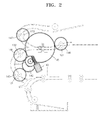
- the first transporting rollers 123, the second transporting rollers 127, the third transporting rollers 131, and the fourth transporting rollers 132 are all connected to one driving source 140 via a row of gears, and thus when the driving source 140 is actuated, each of the first, second, third, and fourth transporting rollers 123, 127, 131, and 132 are driven simultaneously.
- first transporting rollers 123 and the second transporting rollers 127 are referred to as transporting rollers of a first group
- the third transporting rollers 131 and the fourth transporting rollers 132 are referred as transporting rollers of a second group.
- the transporting rollers of the first group are meshed (i.e. interlocked) via a first intermediate gear 145 with a driving gear 141 is meshed with a driving source 140.
- the transporting rollers of the second group are meshed via a second intermediate gear 142 with the driving gear 141 that is meshed with the driving source 140.
- each of the transporting rollers of the first group are identical. Additionally, each of the transporting rollers of the first group are meshed with the intermediate gear 145 and thus are rotated at the same rotation speed. Also, the diameters of each of the transporting rollers of the second group are identical and the transporting rollers of the second group are meshed with the intermediate gear 142 and thus are rotated at the same rotation speed.
- the transporting rollers of a first group are rotated in a direction to transport the document M along the document reading path S2. Additionally, the transporting rollers of a second group are rotated in a direction to transport the print medium P on which a test image T is printed along the missing nozzle detection path S3.
- a driving force may be selectively applied to the transporting rollers of a first group using a conventional clutch as the driving force, thereby not actuating the transporting rollers of a second group.
- a driving force may be selectively applied to the transporting rollers of a second group, thereby not actuating the transporting rollers of a first group.
- An image or test image T is printed on the print medium P along the printing path S1 and the document M is read along the document reading path S2. Since an image printing operation and document reading operation are well known in the art, description thereof will be omitted.
- a print medium P loaded in the cassette 111 is picked up using the pickup roller 112 and is passed through the lower portion of the array inkjet printhead 115, in a forward direction, to form a test image T that corresponds to data associated with a desired image on the print medium P.
- a test image T is formed on the print medium P
- an end of the print medium P on which the test image T is printed should be meshed with the transporting roller 114 in order to transport the print medium P, on which the test image T is formed, in a reverse direction.
- the transporting rollers 114 are rotated in the opposite direction as compared to the direction illustrated in Figure 3 , and transport the print medium P, on which the test image T is printed, in a reverse direction, such that the print medium P with the test image T is fed from the printing path S1 toward the missing nozzle detection path S3.
- the guide unit 119 is then rotated clockwise with respect to Figure 4 and guides the print medium P, on which the test image T is printed, toward the missing nozzle detection path S3.
- the first transporting roller 123 and the second transporting roller 127 are rotated at the same time according to the driving relationship illustrated in Figure 2 and discussed above. Accordingly, the print medium P on which the test image T is printed is transported along the missing nozzle detection path S3.
- the print medium P on which the test image T is printed enters the document reading path S2 and passes through the scanning unit 124 and thus the test image T is scanned or read.
- the print medium P from which the test image T is read is loaded on the document discharge plate 128 by the second transporting roller 127.
- a controlling unit 100a compares the scanned test image T with data corresponding to a desired predetermined image, detects missing portions of the test image T that is read by the scanning unit 124 and accordingly determines if there are any missing nozzles or identifies any nozzle that may have defects as a result of the comparison.
- the nozzle defects are compensated for by performing a correction operation to solve the test image T defects.
- a conventional correction operation may be used as the correction operation of the present embodiment according to the detection of the missing or defective nozzles.
- the multi-functional peripheral device according to the present invention has many advantages, as listed below, including:
- the structure of the multi-functional peripheral device can be simplified and the overall volume thereof can be reduced.
Landscapes
- Engineering & Computer Science (AREA)
- Quality & Reliability (AREA)
- Ink Jet (AREA)
Applications Claiming Priority (1)
| Application Number | Priority Date | Filing Date | Title |
|---|---|---|---|
| KR1020070050269A KR20080103233A (ko) | 2007-05-23 | 2007-05-23 | 미싱노즐검지부를 구비하는 복합기 |
Publications (2)
| Publication Number | Publication Date |
|---|---|
| EP1995072A2 true EP1995072A2 (de) | 2008-11-26 |
| EP1995072A3 EP1995072A3 (de) | 2009-07-22 |
Family
ID=39496123
Family Applications (1)
| Application Number | Title | Priority Date | Filing Date |
|---|---|---|---|
| EP08100670A Withdrawn EP1995072A3 (de) | 2007-05-23 | 2008-01-18 | Bildgebendes Gerät mit einem Element zur Detektion fehlender Düsen |
Country Status (4)
| Country | Link |
|---|---|
| US (1) | US20080291230A1 (de) |
| EP (1) | EP1995072A3 (de) |
| KR (1) | KR20080103233A (de) |
| CN (1) | CN101310984A (de) |
Cited By (3)
| Publication number | Priority date | Publication date | Assignee | Title |
|---|---|---|---|---|
| EP2065205A3 (de) * | 2007-11-30 | 2009-12-23 | Brother Kogyo Kabushiki Kaisha | Bildaufzeichnungsvorrichtung |
| CN103786448A (zh) * | 2012-10-26 | 2014-05-14 | 日本冲信息株式会社 | 图像形成装置 |
| CN115447277A (zh) * | 2021-05-20 | 2022-12-09 | 深圳市汉森软件有限公司 | 自动检测的Onepass打印设备和Onepass打印方法 |
Families Citing this family (5)
| Publication number | Priority date | Publication date | Assignee | Title |
|---|---|---|---|---|
| JP5942568B2 (ja) * | 2012-04-23 | 2016-06-29 | ブラザー工業株式会社 | 画像記録装置 |
| CN104968502B (zh) * | 2012-12-28 | 2018-09-07 | 深圳普赢创新科技股份有限公司 | 多功能打印机 |
| CN108682018B (zh) * | 2018-05-26 | 2019-05-07 | 上海尚雍电子技术工程有限公司 | 设备缺失状况即时检测平台 |
| JP2023151842A (ja) | 2022-04-01 | 2023-10-16 | セイコーエプソン株式会社 | 記録装置 |
| JP2023151829A (ja) * | 2022-04-01 | 2023-10-16 | セイコーエプソン株式会社 | 記録装置 |
Family Cites Families (3)
| Publication number | Priority date | Publication date | Assignee | Title |
|---|---|---|---|---|
| US6412902B2 (en) * | 2000-06-26 | 2002-07-02 | Fuji Photo Film Co., Ltd. | Printing head inspecting device and method for printer |
| GB2384931B (en) * | 2002-01-30 | 2005-06-29 | Hewlett Packard Co | Printer device and method |
| US20060284905A1 (en) * | 2005-06-21 | 2006-12-21 | Xerox Corporation | Dual mode printer output spectrophotometer and input document scanning system |
-
2007
- 2007-05-23 KR KR1020070050269A patent/KR20080103233A/ko not_active Ceased
- 2007-10-23 US US11/876,973 patent/US20080291230A1/en not_active Abandoned
-
2008
- 2008-01-18 EP EP08100670A patent/EP1995072A3/de not_active Withdrawn
- 2008-01-18 CN CNA200810002191XA patent/CN101310984A/zh active Pending
Non-Patent Citations (1)
| Title |
|---|
| None |
Cited By (4)
| Publication number | Priority date | Publication date | Assignee | Title |
|---|---|---|---|---|
| EP2065205A3 (de) * | 2007-11-30 | 2009-12-23 | Brother Kogyo Kabushiki Kaisha | Bildaufzeichnungsvorrichtung |
| CN103786448A (zh) * | 2012-10-26 | 2014-05-14 | 日本冲信息株式会社 | 图像形成装置 |
| CN103786448B (zh) * | 2012-10-26 | 2017-07-14 | 日本冲信息株式会社 | 图像形成装置 |
| CN115447277A (zh) * | 2021-05-20 | 2022-12-09 | 深圳市汉森软件有限公司 | 自动检测的Onepass打印设备和Onepass打印方法 |
Also Published As
| Publication number | Publication date |
|---|---|
| CN101310984A (zh) | 2008-11-26 |
| KR20080103233A (ko) | 2008-11-27 |
| US20080291230A1 (en) | 2008-11-27 |
| EP1995072A3 (de) | 2009-07-22 |
Similar Documents
| Publication | Publication Date | Title |
|---|---|---|
| EP1995072A2 (de) | Bildgebendes Gerät mit einem Element zur Detektion fehlender Düsen | |
| US7762549B2 (en) | Recording apparatus | |
| KR101366257B1 (ko) | 잉크젯 화상형성장치 | |
| JP2024046491A (ja) | 画像形成装置 | |
| US7083245B2 (en) | Recording apparatus | |
| JPH09284478A (ja) | 画像読取装置及び画像形成装置 | |
| JP7667949B2 (ja) | 画像形成装置 | |
| US7236736B2 (en) | Image recording apparatus | |
| JP2024046488A (ja) | 画像形成装置 | |
| JP2006282349A (ja) | 画像形成装置 | |
| JP2004085668A (ja) | 画像形成装置 | |
| JP4572489B2 (ja) | 複合処理装置及びその制御方法 | |
| JP7737615B2 (ja) | 画像形成装置 | |
| US20050206074A1 (en) | Sheet conveyer and image recording apparatus | |
| JPH1134403A (ja) | 記録装置及び記録方法 | |
| JP2024077531A (ja) | 搬送装置、印刷装置 | |
| JP2024123915A (ja) | 画像形成装置 | |
| JP2024176938A (ja) | 媒体処理装置 | |
| JP2024131854A (ja) | 画像形成装置 | |
| JP4590316B2 (ja) | 画像記録装置の仕分け装置、及びその仕分け装置における仕分け方法 | |
| JP2025119271A (ja) | 画像形成装置 | |
| JP2011051796A (ja) | 用紙処理装置、用紙処理方法、画像形成装置、画像形成システム、画像形成方法、プログラム及び記録媒体 | |
| JP2023048314A (ja) | 画像形成装置 | |
| JP2006175777A (ja) | サーマルプリンタ装置 | |
| JP2023064222A (ja) | 画像形成装置 |
Legal Events
| Date | Code | Title | Description |
|---|---|---|---|
| PUAI | Public reference made under article 153(3) epc to a published international application that has entered the european phase |
Free format text: ORIGINAL CODE: 0009012 |
|
| AK | Designated contracting states |
Kind code of ref document: A2 Designated state(s): AT BE BG CH CY CZ DE DK EE ES FI FR GB GR HR HU IE IS IT LI LT LU LV MC MT NL NO PL PT RO SE SI SK TR |
|
| AX | Request for extension of the european patent |
Extension state: AL BA MK RS |
|
| PUAL | Search report despatched |
Free format text: ORIGINAL CODE: 0009013 |
|
| AK | Designated contracting states |
Kind code of ref document: A3 Designated state(s): AT BE BG CH CY CZ DE DK EE ES FI FR GB GR HR HU IE IS IT LI LT LU LV MC MT NL NO PL PT RO SE SI SK TR |
|
| AX | Request for extension of the european patent |
Extension state: AL BA MK RS |
|
| 17P | Request for examination filed |
Effective date: 20100120 |
|
| 17Q | First examination report despatched |
Effective date: 20100212 |
|
| AKX | Designation fees paid |
Designated state(s): DE FR GB NL |
|
| STAA | Information on the status of an ep patent application or granted ep patent |
Free format text: STATUS: THE APPLICATION IS DEEMED TO BE WITHDRAWN |
|
| 18D | Application deemed to be withdrawn |
Effective date: 20110301 |