EP1995084A1 - Niederhalter - Google Patents
Niederhalter Download PDFInfo
- Publication number
- EP1995084A1 EP1995084A1 EP08450049A EP08450049A EP1995084A1 EP 1995084 A1 EP1995084 A1 EP 1995084A1 EP 08450049 A EP08450049 A EP 08450049A EP 08450049 A EP08450049 A EP 08450049A EP 1995084 A1 EP1995084 A1 EP 1995084A1
- Authority
- EP
- European Patent Office
- Prior art keywords
- hold
- contact element
- spherical
- down device
- holding
- Prior art date
- Legal status (The legal status is an assumption and is not a legal conclusion. Google has not performed a legal analysis and makes no representation as to the accuracy of the status listed.)
- Granted
Links
Images

Classifications
-
- B—PERFORMING OPERATIONS; TRANSPORTING
- B60—VEHICLES IN GENERAL
- B60D—VEHICLE CONNECTIONS
- B60D1/00—Traction couplings; Hitches; Draw-gear; Towing devices
- B60D1/01—Traction couplings or hitches characterised by their type
- B60D1/06—Ball-and-socket hitches
- B60D1/065—Ball-and-socket hitches characterised by the hitch mechanism
-
- B—PERFORMING OPERATIONS; TRANSPORTING
- B60—VEHICLES IN GENERAL
- B60D—VEHICLE CONNECTIONS
- B60D1/00—Traction couplings; Hitches; Draw-gear; Towing devices
- B60D1/24—Traction couplings; Hitches; Draw-gear; Towing devices characterised by arrangements for particular functions
- B60D1/28—Traction couplings; Hitches; Draw-gear; Towing devices characterised by arrangements for particular functions for preventing unwanted disengagement, e.g. safety appliances
-
- B—PERFORMING OPERATIONS; TRANSPORTING
- B60—VEHICLES IN GENERAL
- B60D—VEHICLE CONNECTIONS
- B60D1/00—Traction couplings; Hitches; Draw-gear; Towing devices
- B60D1/58—Auxiliary devices
- B60D1/583—Holding-down means, e.g. holding-down retainers
-
- B—PERFORMING OPERATIONS; TRANSPORTING
- B60—VEHICLES IN GENERAL
- B60D—VEHICLE CONNECTIONS
- B60D1/00—Traction couplings; Hitches; Draw-gear; Towing devices
- B60D1/58—Auxiliary devices
- B60D1/586—Lubrication means
Definitions
- the invention relates to a hold-down according to the preamble of claim 1.
- the object of the invention is to provide a hold-down device of the type mentioned, with which the mentioned disadvantages avoided and with which the wear of the blank holder can be kept low, a secure hold of the drawbar eye can be ensured on the coupling ball, and easy and inexpensive to produce is.
- the contact element Due to the pivotable arrangement of the contact element in the hold-down housing dimensional inaccuracies can be compensated, whereby a flat support of the contact element is ensured on the towing eye.
- the contact element When changing the drawbar, the contact element is in each case to the currently used towing eye, whereby a largely flat contact of the contact element is achieved on the towing eye.
- a flat support provides a good grip of the drawbar eye on the coupling ball, in particular when a holding force is exerted on the towing eye by means of the contact element.
- the stresses in the contact element can be kept low, as a result of which a low probability of failure and a high service life of the parts are achieved.
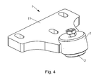
- Fig. 1 to 4 show embodiments of a hold-down 1 for holding a arranged on a coupling ball drawbar, with a contact element 3 for cooperation with the towing eye.
- Such hold-down device 1 are used in couplings with a coupling ball, on the one hand the coupling ball and the hold-down 1 and on the other hand, the drawbar eye is mounted on a vehicle or trailer.
- the coupling ball and the hold-1 are mounted on the towing vehicle.
- the hold-down device 1 comprises a hold-down housing 2 with an open-edged recess 21, wherein the open-edged recess 21 has an opening 22 for receiving the contact element 3.
- the contact element 3 is arranged pivotably in the open-edged recess 21.
- the drawbar eye is in contact with the contact element 3.
- the contact element 3 may be formed as a wear part, which preferably has a lower strength than the surface of the towing eye. This can ensure that the towing eye remains largely undamaged in the event of material erosion.
- the contact element 3 may comprise a lubricant and / or lubrication openings, whereby a good lubricity of the contact element 3 can be achieved on the drawbar.
- the contact element 3 can automatically align so that the largest possible surface contact between the contact element 3 and the drawbar is formed, which in particular Hersellungstoleranzen or other deviations can be compensated. In particular, can be dispensed with a readjustment in a change of the towing eye.
- the contact element 3 has a contact surface 31, which is provided for contact with the drawbar eye.
- the contact surface 31 may be formed opposite to the towing eye. In this case, the contact surface 31 usually has an inwardly curved surface.
- the open-edged recess 21 may be arranged in the coupled state in the vicinity of the drawbar eye and form a protection of the contact element 3.
- the hold-down housing 2 contribute to the stability of the blank holder 1 in this area. It can further be ensured that essentially only compressive and shear stresses are to be absorbed by the contact element 3.
- a first spherical portion 23 may be formed at the opening 22 opposite wall of the open-edged recess 21 at the opening 22 opposite wall of the open-edged recess 21, a first spherical portion 23 may be formed. With the first spherical portion 23, a pivotable arrangement of the contact element 3 can be achieved in a simple manner, wherein a rotationally symmetrical pivotability can be provided.
- the contact element 3 may have a region which is opposite to the first spherical region 23 and which cooperates with the first spherical region 23.
- the first spherical portion 23 gegentechnisches intermediate piece 4 is arranged, wherein the first intermediate piece 4 is arranged pivotably relative to the hold-down housing 2 and the contact element 3 is connected to the intermediate piece 4.
- the contact element 3 can be made particularly simple, whereby a cost-effective replacement is made possible.
- the intermediate piece 4 usually remains in the hold-down housing 2 and can be manufactured with small tolerances.
- the hold-down housing 2 made of metal and the intermediate piece 4 is made of a plastic material.
- the force required for pivoting the contact element 3 can be kept low. If necessary, then the intermediate piece 4 can be easily replaced, with damage to the hold-down housing during operation can be largely avoided.
- the intermediate piece 4 can essentially perform a sliding movement in the open-edged recess 21.
- a cylindrical area 24 may be formed, wherein the contact element 3 is arranged substantially in the cylindrical area 24.
- a through-opening 25 may be formed to an outer side 26 of the hold-down housing 2 opposite the first spherical region 23, wherein the outer side 26 is formed as a second spherical region 27 in the region of the through-opening 25 and wherein the first spherical region 23 and the second spherical portion 27 are substantially concentric.
- a holding element 5 connected to the contact element 3 can be supported by means of a supporting element 51, wherein the supporting element 51 is displaceably arranged on the second spherical area 27.
- the holding element 5 may have a lubricating opening.
- it may have a continuous lubrication channel, whereby a lubricant can be brought into the contact area between the contact element 3 and the towing eye in a simple manner.
- the contact element 3 can be easily supported on the hold-down housing 2, wherein the concentric configuration of the first spherical portion 23 and the second spherical portion 27 substantially allows a rigid body movement of the contact element 3 and the holding member 5 about the common center.
- the pivotability of the contact element 3 relative to the hold-down housing 2 may be determined essentially by the size of the through-opening 25.
- the second spherical portion 27 is disposed in operation on a side remote from the drawbar eye of the hold-down housing 2. If the towing eye has encrustations of dirt or the like, which are removed by the relative movement of the drawbar eye relative to the contact element 3, damage to the second spherical region can largely be avoided due to the protected arrangement of the second spherical region 27.
- the support member 51 may be detachably connected to the holding member 5. Thereby, a particularly simple replacement of the contact element 3 are made possible, it being possible for the support element 51 to be provided after the contact element 3 has been removed from the open-edged recess 21 through the passage opening 25.
- the holding element 51 can be detached from the contact element 3 and replaced by a new contact element 3.
- a damping element 6 may be arranged, wherein the damping element 6 is preferably formed as a spring element and / or as an elastomeric element.
- the contact element 3 can be sprung in the hold-down housing 21 are arranged and exercised in the placement of the contact element 3 on the towing eye a holding force on the drawbar eye in the direction of the coupling ball.
- a particularly smooth driving behavior can be achieved, wherein the unloaded drawbar eye is always held firmly on the coupling ball.
- impacts in the direction of the hold-down device 1 are received by the hold-down housing 2.
- the hold-down 1 is particularly suitable for use in a pick-up hitch, which has a mounting bracket and a swivel bracket pivotally mounted relative to the mounting bracket.
- a carriage element may be performed in the swivel bracket.
- the coupling ball is connected to the carriage element or with the swivel bracket and the hold-down 1 with the mounting bracket.
- the relative movement between the coupling ball and the hold-down is carried out by the movement of the pivoting console and the carriage element, whereby a firm connection of the coupling ball can be provided with the carriage member and the blank holder 1 with the mounting bracket.
- the hold-down device may have a flange plate 11 with which the hold-down housing 2 is connected via a web element 12.
- the hold-down 1 may be attached to a base plate, wherein the coupling ball is connected to the base plate.
- the hold-down device 1 can be arranged pivotably and / or displaceably relative to the base plate.
- the coupling ball relative to the base plate can be arranged pivotably and / or displaceably.
Landscapes
- Engineering & Computer Science (AREA)
- Transportation (AREA)
- Mechanical Engineering (AREA)
- Pivots And Pivotal Connections (AREA)
- Polishing Bodies And Polishing Tools (AREA)
- Mechanical Treatment Of Semiconductor (AREA)
- Electromechanical Clocks (AREA)
- Connector Housings Or Holding Contact Members (AREA)
Abstract
Description
- Die Erfindung betrifft einen Niederhalter gemäß dem Oberbegriff des Patentanspruches 1.
- Es ist bekannt bei Kupplungen mit einer Kupplungskugel einen Niederhalter vorzusehen, der ein Abheben einer auf die Kupplungskugel aufgesetzten Zugöse verhindert. Durch die Relativbewegung zwischen der Zugöse und dem Niederhalter tritt bei dem Niederhalter ein Verschleiß auf. Insbesondere bei dem Einsatz mehrerer Zugösen kann es zu einem vermehrten Verschleiß kommen.
- Aufgabe der Erfindung ist es, einen Niederhalter der eingangs genannten Art anzugeben, mit welchem die genannten Nachteile vermieden und mit welchem der Verschleiß des Niederhalters gering gehalten werden kann, ein sicherer Halt der Zugöse auf der Kupplungskugel sichergestellt werden kann, und der einfach und kostengünstig herstellbar ist.
- Erfindungsgemäß wird dies durch die Merkmale des Patentanspruches 1 erreicht.
- Durch die verschwenkbare Anordnung des Kontaktelementes in dem Niederhaltergehäuse können Maßungenauigkeiten ausgeglichen werden, wodurch eine flächige Auflage des Kontaktelementes auf der Zugöse sichergestellt wird. Bei einem Wechsel der Zugöse stellt sich das Kontaktelement jeweils an die derzeit verwendete Zugöse ein, wodurch eine weitgehend flächige Auflage des Kontaktelementes auf der Zugöse erreicht wird. Eine flächige Auflage bietet einen guten Halt der Zugöse auf der Kupplungskugel, insbesondere wenn mittels des Kontaktelementes eine Haltekraft auf die Zugöse ausgeübt wird. Weiters können bei einer flächigen Auflage die Spannungen in dem Kontaktelement gering gehalten werden, wodurch eine geringe Ausfallswahrscheinlichkeit und eine hohe Lebensdauer der Teile erreicht wird.
- Die Unteransprüche, welche ebenso wie der Patentanspruch 1 gleichzeitig einen Teil der Beschreibung bilden, betreffen weitere vorteilhafte Ausgestaltungen der Erfindung.
- Die Erfindung wird unter Bezugnahme auf die beigeschlossenen Zeichnungen, in welchen lediglich bevorzugte Ausführungsformen beispielhaft dargestellt sind, näher beschrieben. Dabei zeigt:
-
Fig. 1 eine Seitenansicht auf eine Ausführungsform eines erfindungsgemäßen Niederhalters; -
Fig. 2 und 3 jeweils eine Seitenansicht auf den Niederhalter gemäßFig. 1 , mit einem verschwenkten Kontaktelement; und -
Fig. 4 eine weitere Ausführungsform des erfindungsgemäßen Niederhalters im Schrägriss. - Die
Fig. 1 bis 4 zeigen Ausführungsformen eines Niederhalters 1 zum Halten einer auf einer Kupplungskugel angeordneten Zugöse, mit einem Kontaktelement 3 zum Zusammenwirken mit der Zugöse. - Derartige Niederhalter 1 werden bei Kupplungen mit einer Kupplungskugel eingesetzt, wobei einerseits die Kupplungskugel und der Niederhalter 1 und andererseits die Zugöse auf einem Fahrzeug bzw. Anhänger montiert ist. Üblicherweise sind die Kupplungskugel und der Niederhalter 1 am Zugfahrzeug montiert.
- Während des Kuppelvorgangs tritt eine Relativbewegung zwischen dem Niederhalter 1 und die Kupplungskugel auf, wobei im gekuppelten Zustand die Zugöse mit der Kupplungskugel und dem Niederhalter 1 in Kontakt ist und in einem offenen Zustand der Niederhalter 1 so weit von der Kupplungskugel entfernt ist, dass die Zugöse von der Kupplungskugel genommen werden kann.
- Der Niederhalter 1 umfasst ein Niederhaltergehäuse 2 mit einer randoffenen Ausnehmung 21, wobei die randoffene Ausnehmung 21 eine Öffnung 22 zur Aufnahme des Kontaktelementes 3 aufweist. Das Kontaktelement 3 ist verschwenkbar in der randoffenen Ausnehmung 21 angeordnet.
- Im gekuppelten Zustand ist die Zugöse mit dem Kontaktelement 3 in Kontakt. Dabei kann das Kontaktelement 3 als Verschleißteil ausgebildet sein, welches vorzugsweise eine geringere Festigkeit als die Oberfläche der Zugöse aufweist. Dadurch kann sichergestellt werden, dass bei dem Auftreten von Materialabtragungen die Zugöse weitgehend unbeschädigt bleibt.
- Das Kontaktelement 3 kann ein Gleitmittel und/oder Schmieröffnungen umfassen, wodurch eine gute Gleitfähigkeit des Kontaktelementes 3 auf der Zugöse erreichbar ist.
- Durch die verschwenkbare Anordnung des Kontaktelementes 3 in dem Niederhaltergehäuse 2 kann sich das Kontaktelement 3 selbsttätig so ausrichten, dass eine möglichst großflächige Auflage zwischen dem Kontaktelement 3 und der Zugöse ausgebildet wird, wodurch insbesondere Hersellungstoleranzen oder sonstige Maßabweichungen ausgeglichen werden können. Insbesondere kann auf eine Nachjustierung bei einem Wechsel der Zugöse verzichtet werden.
- Das Kontaktelement 3 weist eine Kontaktfläche 31 auf, die zum Kontakt mit der Zugöse vorgesehen ist. Die Kontaktfläche 31 kann gegengleich zur Zugöse ausgebildet sein. Dabei weist die Kontaktfläche 31 üblicherweise eine nach innen gekrümmte Oberfläche auf.
- Die randoffene Ausnehmung 21 kann im gekuppelten Zustand in der Nähe der Zugöse angeordnet sein und einen Schutz des Kontaktelementes 3 ausbilden. Dabei kann das Niederhaltergehäuse 2 in diesem Bereich zur Stabilität des Niederhalters 1 beitragen. Es kann weiters sichergestellt werden, dass von dem Kontaktelement 3 im Wesentlichen lediglich Druck- und Scherbeanspruchungen aufzunehmen sind.
- An der der Öffnung 22 gegenüberliegenden Wandung der randoffenen Ausnehmung 21 kann ein erster kugelförmiger Bereich 23 ausgebildet sein. Mit dem ersten kugelförmigen Bereich 23 kann auf einfache Weise eine verschwenkbare Anordnung des Kontaktelementes 3 erreicht werden, wobei eine rotationssymmetrische Verschwenkbarkeit bereitgestellt werden kann.
- Das Kontaktelement 3 kann einen dem ersten kugelförmigen Bereich 23 gegengleichen Bereich aufweisen, der mit dem ersten kugelförmigen Bereich 23 zusammenwirkt.
- Es kann auch vorgesehen sein, dass in dem ersten kugelförmigen Bereich 23 ein dem ersten kugelförmigen Bereich 23 gegengleiches Zwischenstück 4 angeordnet ist, wobei das erste Zwischenstück 4 gegenüber dem Niederhaltergehäuse 2 verschwenkbar angeordnet ist und das Kontaktelement 3 mit dem Zwischenstück 4 verbunden ist. Dadurch kann auf einfache Weise eine unterschiedliche Materialkombination für das Ausbilden der verschwenkbaren Anordnung des Kontaktelementes 3 im Niederhaltergehäuse 2 und dem Zusammenwirken des Kontaktelementes 3 mit der Zugöse bereitgestellt werden. Weiters kann das Kontaktelement 3 besonders einfach ausgebildet werden, wodurch ein kostengünstiger Austausch ermöglicht wird.
- Das Zwischenstück 4 verbleibt üblicherweise in dem Niederhaltergehäuse 2 und kann mit geringen Toleranzen hergestellt werden. Insbesondere kann vorgesehen sein, dass das Niederhaltergehäuse 2 aus Metall und das Zwischenstück 4 aus einem Kunststoffmaterial ist. Dadurch kann die erforderliche Kraft zum Verschwenken des Kontaktelementes 3 gering gehalten werden. Bei Bedarf kann dann das Zwischenstück 4 einfach ausgetauscht werden, wobei eine Beschädigung des Niederhaltergehäuses während des Betriebs weitgehend vermieden werden kann.
- Bei der Verschwenkbewegung des Kontaktelementes 3 kann das Zwischenstück 4 im Wesentlichen eine Gleitbewegung in der randoffenen Ausnehmung 21 ausführen.
- Zwischen der Öffnung 22 und dem ersten kugelförmigen Bereich 23 kann ein zylindrischer Bereich 24 ausgebildet sein, wobei das Kontaktelement 3 im Wesentlichen in dem zylindrischen Bereich 24 angeordnet ist.
- In dem ersten kugelförmigen Bereich 23 kann eine Durchgangsöffnung 25 zu einer dem ersten kugelförmigen Bereich 23 gegenüberliegende Außenseite 26 des Niederhaltergehäuses 2 ausgebildet sein, wobei die Außenseite 26 im Bereich der Durchgangsöffnung 25 als zweiter kugelförmiger Bereich 27 ausgebildet ist und wobei der erste kugelförmige Bereich 23 und der zweite kugelförmige Bereich 27 im Wesentlichen konzentrisch sind.
- An dem zweiten kugelförmigen Bereich 27 kann ein mit dem Kontaktelement 3 verbundenes Halteelement 5 mittels eines Abstützelementes 51 abgestützt sein, wobei das Abstützelement 51 auf dem zweiten kugelförmigen Bereich 27 verschiebbar angeordnet ist.
- Das Halteelement 5 kann eine Schmieröffnung aufweisen. Insbesondere kann es einen durchgehenden Schmierkanal aufweisen, wodurch auf einfache Weise ein Schmiermittel in den Kontaktbereich zwischen dem Kontaktelement 3 und der Zugöse gebracht werden kann.
- Auf diese Weise kann das Kontaktelement 3 einfach an dem Niederhaltergehäuse 2 abgestützt werden, wobei die konzentrische Ausgestaltung des ersten kugelförmigen Bereiches 23 und des zweiten kugelförmigen Bereiches 27 im Wesentlichen eine Starrkörperbewegung des Kontaktelementes 3 und des Halteelementes 5 um den gemeinsamen Mittelpunkt ermöglicht.
- Die Verschwenkbarkeit des Kontaktelementes 3 gegenüber dem Niederhaltergehäuse 2 kann im Wesentlichen durch die Größe der Durchgangsöffnung 25 bestimmt sein.
- Der zweite kugelförmige Bereich 27 ist im Betrieb auf einer der Zugöse abgewandten Seite des Niederhaltergehäuses 2 angeordnet. Weist die Zugöse Verkrustungen von Schmutz od. dgl. auf, welche durch die Relativbewegung der Zugöse gegenüber dem Kontaktelement 3 entfernt werden, so kann aufgrund der geschützten Anordnung des zweiten kugelförmigen Bereiches 27 eine Beschädigung des zweiten kugelförmigen Bereiches weitgehend vermieden werden.
- Die Ablösung von weiter abstehenden Verkrustungen od. dgl. kann durch das in der Nähe der Zugöse angeordnete Niederhaltergehäuse 2 erfolgen.
- Das Abstützelement 51 kann lösbar mit dem Halteelement 5 verbunden sein. Dadurch kann ein besonders einfaches Austauschen des Kontaktelementes 3 ermöglicht werden, wobei nach Lösen des Abstützelementes 51 vorgesehen sein kann, dass das Halteelement bei dem Herausnehmen des Kontaktelementes 3 aus der randoffenen Ausnehmung 21 durch die Durchgangsöffnung 25 geführt wird.
- Anschließend kann vorgesehen sein, dass das Halteelement 51 von dem Kontaktelement 3 gelöst und durch ein neues Kontaktelement 3 ersetzt werden kann.
- Zwischen dem Zwischenstück 4 und dem Kontaktelement 3 kann ein Dämpfungselement 6 angeordnet sein, wobei das Dämpfungselement 6 vorzugsweise als Federelement und/oder als Elastomerelement ausgebildet ist. Auf diese Weise kann das Kontaktelement 3 gefedert in dem Niederhaltergehäuse 21 angeordnet werden und bei dem Aufsetzen des Kontaktelementes 3 auf die Zugöse eine Haltekraft auf die Zugöse in Richtung der Kupplungskugel ausgeübt werden. Dadurch kann ein besonders ruhiges Fahrverhalten erreicht werden, wobei die unbelastete Zugöse immer fest auf der Kupplungskugel gehalten wird. Im Betrieb kann vorgesehen sein, dass Stöße in Richtung des Niederhalters 1 von dem Niederhaltergehäuse 2 aufgenommen werden.
- Bei einer Kupplung mit einem oben beschriebenen Niederhalter 1 können oben beschriebenen Vorteile für die Kupplung bereitgestellt werden.
- Der erfindungsgemäße Niederhalter 1 eignet sich insbesondere für den Einsatz bei einer Pick-Up-Hitch, welche eine Anbaukonsole und eine gegenüber der Anbaukonsole verschwenkbar gelagerte Schwenkkonsole aufweist. In der Schwenkkonsole kann ein Schlittenelement geführt sein. Dabei ist die Kupplungskugel mit dem Schlittenelement bzw. mit der Schwenkkonsole verbunden und der Niederhalter 1 mit der Anbaukonsole. Die Relativbewegung zwischen der Kupplungskugel und dem Niederhalter wird durch die Bewegung der Schwenkkonsole und des Schlittenelementes durchgeführt, wodurch eine feste Anbindung der Kupplungskugel mit dem Schlittenelement und des Niederhalters 1 mit der Anbaukonsole vorgesehen sein kann.
- Für die Befestigung an der Anbaukonsole kann der Niederhalter eine Flanschplatte 11 aufweisen, mit der über ein Stegelement 12 das Niederhaltergehäuse 2 verbunden ist.
- Bei der Ausführungsform gemäß
Fig. 4 ist das Niederhaltergehäuse 2 unmittelbar mit der Flanschplatte 11 verbunden. - Bei anderen Ausführungsformen kann der Niederhalter 1 an einer Grundplatte befestigt sein, wobei auch die Kupplungskugel mit der Grundplatte verbunden ist. Dabei kann der Niederhalter 1 gegenüber der Grundplatte verschwenkbar und/oder verschiebbar angeordnet sein. Bei wieder anderen Ausführungsformen kann auch die Kupplungskugel gegenüber der Grundplatte verschwenkbar und/oder verschiebbar angeordnet sein.
- Weitere erfindungsgemäße Ausführungsformen weisen lediglich einen Teil der beschriebenen Merkmale auf, wobei jede Merkmalskombination, insbesondere auch von verschiedenen beschriebenen Ausführungsformen, vorgesehen sein kann.
Claims (8)
- Niederhalter (1) zum Halten einer auf einer Kupplungskugel angeordneten Zugöse, mit einem Kontaktelement (3) zum Zusammenwirken mit der Zugöse dadurch gekennzeichnet, dass der Niederhalter (1) ein Niederhaltergehäuse (2) mit einer randoffenen Ausnehmung (21) umfasst, wobei die randoffene Ausnehmung (21) eine Öffnung (22) zur Aufnahme des Kontaktelementes (3) aufweist, und dass das Kontaktelement (3) verschwenkbar in der randoffenen Ausnehmung (21) angeordnet ist.
- Niederhalter nach Anspruch 1, dadurch gekennzeichnet, dass an der der Öffnung (22) gegenüberliegenden Wandung der randoffenen Ausnehmung (21) ein erster kugelförmiger Bereich (23) ausgebildet ist.
- Niederhalter nach Anspruch 2, dadurch gekennzeichnet, dass in dem ersten kugelförmigen Bereich (23) ein dem ersten kugelförmigen Bereich (23) gegengleiches Zwischenstück (4) angeordnet ist, wobei das erste Zwischenstück (4) gegenüber dem Niederhaltergehäuse (2) verschwenkbar angeordnet ist und das Kontaktelement (3) mit dem Zwischenstück (4) verbunden ist.
- Niederhalter nach Anspruch 2 oder 3, dadurch gekennzeichnet, dass in dem ersten kugelförmigen Bereich (23) eine Durchgangsöffnung (25) zu einer dem ersten kugelförmigen Bereich (23) gegenüberliegenden Außenseite (26) des Niederhaltergehäuses (2) ausgebildet ist und die Außenseite (26) im Bereich der Durchgangsöffnung (25) als zweiter kugelförmiger Bereich (27) ausgebildet ist, wobei der erste kugelförmige Bereich (23) und der zweite kugelförmige Bereich (27) im Wesentlichen konzentrisch sind.
- Niederhalter nach Anspruch 4, dadurch gekennzeichnet, dass ein mit dem Kontaktelement (3) verbundenes Halteelement (5) an dem zweiten kugelförmigen Bereich (27) mittels eines Abstützelementes (51) abgestützt ist, wobei das Abstützelement (51) auf dem zweiten kugelförmigen Bereich (27) verschiebbar angeordnet ist.
- Niederhalter nach Anspruch 5, dadurch gekennzeichnet, dass das Abstützelement (51) lösbar mit dem Halteelement (5) verbunden ist.
- Niederhalter nach einem der Ansprüche 3 bis 6, dadurch gekennzeichnet, dass zwischen dem Zwischenstück (4) und dem Kontaktelement (3) ein Dämpfungselement (6) angeordnet ist, wobei das Dämpfungselement (6) vorzugsweise als Federelement und/oder als Elastomerelement ausgebildet ist.
- Kupplung mit einer Kupplungskugel und einem Niederhalter (1) gemäß einem der Ansprüche 1 bis 7.
Applications Claiming Priority (1)
| Application Number | Priority Date | Filing Date | Title |
|---|---|---|---|
| AT0079907A AT504477B1 (de) | 2007-05-22 | 2007-05-22 | Niederhalter |
Publications (2)
| Publication Number | Publication Date |
|---|---|
| EP1995084A1 true EP1995084A1 (de) | 2008-11-26 |
| EP1995084B1 EP1995084B1 (de) | 2010-06-09 |
Family
ID=39494767
Family Applications (1)
| Application Number | Title | Priority Date | Filing Date |
|---|---|---|---|
| EP08450049A Not-in-force EP1995084B1 (de) | 2007-05-22 | 2008-04-01 | Niederhalter |
Country Status (3)
| Country | Link |
|---|---|
| EP (1) | EP1995084B1 (de) |
| AT (2) | AT504477B1 (de) |
| DE (1) | DE502008000762D1 (de) |
Cited By (1)
| Publication number | Priority date | Publication date | Assignee | Title |
|---|---|---|---|---|
| EP2596967A1 (de) * | 2011-10-07 | 2013-05-29 | AGCO International GmbH | Kupplungskopplungsvorrichtung |
Citations (3)
| Publication number | Priority date | Publication date | Assignee | Title |
|---|---|---|---|---|
| BE429538A (de) * | ||||
| US5683094A (en) * | 1996-12-13 | 1997-11-04 | Jeffrey Gullickson | Universal, energy-absorbent trailer hitch |
| EP1437241A1 (de) * | 2002-12-20 | 2004-07-14 | Josef Scharmüller | Pick-up-hitch Anhängerkupplung |
-
2007
- 2007-05-22 AT AT0079907A patent/AT504477B1/de not_active IP Right Cessation
-
2008
- 2008-04-01 EP EP08450049A patent/EP1995084B1/de not_active Not-in-force
- 2008-04-01 DE DE502008000762T patent/DE502008000762D1/de active Active
- 2008-04-01 AT AT08450049T patent/ATE470584T1/de active
Patent Citations (3)
| Publication number | Priority date | Publication date | Assignee | Title |
|---|---|---|---|---|
| BE429538A (de) * | ||||
| US5683094A (en) * | 1996-12-13 | 1997-11-04 | Jeffrey Gullickson | Universal, energy-absorbent trailer hitch |
| EP1437241A1 (de) * | 2002-12-20 | 2004-07-14 | Josef Scharmüller | Pick-up-hitch Anhängerkupplung |
Cited By (1)
| Publication number | Priority date | Publication date | Assignee | Title |
|---|---|---|---|---|
| EP2596967A1 (de) * | 2011-10-07 | 2013-05-29 | AGCO International GmbH | Kupplungskopplungsvorrichtung |
Also Published As
| Publication number | Publication date |
|---|---|
| AT504477A4 (de) | 2008-06-15 |
| DE502008000762D1 (de) | 2010-07-22 |
| ATE470584T1 (de) | 2010-06-15 |
| EP1995084B1 (de) | 2010-06-09 |
| AT504477B1 (de) | 2008-06-15 |
Similar Documents
| Publication | Publication Date | Title |
|---|---|---|
| EP1554068B1 (de) | Abstreifeinrichtung | |
| DE102013221440A1 (de) | Scheibenwischer vom Typ eines Flachwischerblatts mit verbesserterEndkappen-Struktur | |
| DE102006008837A1 (de) | Anhängerkupplung für Kraftfahrzeuge | |
| EP1995084B1 (de) | Niederhalter | |
| DE102009045653B4 (de) | Schiene einer Längsführung mit einem Lagerbock und einer schwenkbaren Klappe | |
| EP2356009B1 (de) | Kupplungseinheit | |
| EP2524752B1 (de) | Entgratwerkzeughalter | |
| DE212006000058U1 (de) | Handhabungswerkzeug für Verglasungen | |
| DE3314404C2 (de) | Fahrkabinen-Kippsystem | |
| DE102020110855A1 (de) | Antriebsbit mit gefederter Buchse | |
| AT504478B1 (de) | Niederhalter | |
| DE102018206889A1 (de) | Zerspanungswerkzeug mit Tiefenanschlag | |
| DE102015213438A1 (de) | Stanznietvorrichtung und Fertigungsvorrichtung | |
| WO2005058546A1 (de) | Festwalzrollenkopf für split-pin-kurbelwellen | |
| EP3123052B1 (de) | Spindelhalterung für eine nachstelleinrichtung | |
| DE10303844A1 (de) | Montagewerkzeug und geeignete Handhabungseinrichtung | |
| DE10317345B4 (de) | Schnellspannsystem mit Zentriervorrichtung | |
| DE112013005789B4 (de) | Wischerkopplungsadapter und Wischeranordnung, welche denselbigen enthält | |
| EP2692554B1 (de) | Anhängekupplung mit einer Verriegelungseinrichtung | |
| DE10125151B4 (de) | Biegevorrichtung | |
| DE102020120993B4 (de) | Vorrichtung zum Bearbeiten einer Oberfläche | |
| DE102010051152A1 (de) | Deckelfeste Ausrückvorrichtung für Fahrzeugkupplungen | |
| DE102013108896A1 (de) | Schälgerät zur schälenden Bearbeitung des Außen- oder Innenumfangs rohrförmiger Gegenstände | |
| DE102011050680A1 (de) | Verstelleinheit, insbesondere zur Ausrichtung von Bauteilen im Fahrzeugbau, sowie Verfahren zum Einstellen einer derartigen Verstelleinheit | |
| DE102007055890A1 (de) | Rakeleinrichtung |
Legal Events
| Date | Code | Title | Description |
|---|---|---|---|
| PUAI | Public reference made under article 153(3) epc to a published international application that has entered the european phase |
Free format text: ORIGINAL CODE: 0009012 |
|
| AK | Designated contracting states |
Kind code of ref document: A1 Designated state(s): AT BE BG CH CY CZ DE DK EE ES FI FR GB GR HR HU IE IS IT LI LT LU LV MC MT NL NO PL PT RO SE SI SK TR |
|
| AX | Request for extension of the european patent |
Extension state: AL BA MK RS |
|
| 17P | Request for examination filed |
Effective date: 20090526 |
|
| AKX | Designation fees paid |
Designated state(s): AT BE BG CH CY CZ DE DK EE ES FI FR GB GR HR HU IE IS IT LI LT LU LV MC MT NL NO PL PT RO SE SI SK TR |
|
| GRAP | Despatch of communication of intention to grant a patent |
Free format text: ORIGINAL CODE: EPIDOSNIGR1 |
|
| GRAS | Grant fee paid |
Free format text: ORIGINAL CODE: EPIDOSNIGR3 |
|
| GRAA | (expected) grant |
Free format text: ORIGINAL CODE: 0009210 |
|
| AK | Designated contracting states |
Kind code of ref document: B1 Designated state(s): AT BE BG CH CY CZ DE DK EE ES FI FR GB GR HR HU IE IS IT LI LT LU LV MC MT NL NO PL PT RO SE SI SK TR |
|
| REG | Reference to a national code |
Ref country code: CH Ref legal event code: EP |
|
| REG | Reference to a national code |
Ref country code: IE Ref legal event code: FG4D Free format text: LANGUAGE OF EP DOCUMENT: GERMAN |
|
| REF | Corresponds to: |
Ref document number: 502008000762 Country of ref document: DE Date of ref document: 20100722 Kind code of ref document: P |
|
| REG | Reference to a national code |
Ref country code: NL Ref legal event code: VDEP Effective date: 20100609 |
|
| PG25 | Lapsed in a contracting state [announced via postgrant information from national office to epo] |
Ref country code: LT Free format text: LAPSE BECAUSE OF FAILURE TO SUBMIT A TRANSLATION OF THE DESCRIPTION OR TO PAY THE FEE WITHIN THE PRESCRIBED TIME-LIMIT Effective date: 20100609 Ref country code: NO Free format text: LAPSE BECAUSE OF FAILURE TO SUBMIT A TRANSLATION OF THE DESCRIPTION OR TO PAY THE FEE WITHIN THE PRESCRIBED TIME-LIMIT Effective date: 20100909 Ref country code: SE Free format text: LAPSE BECAUSE OF FAILURE TO SUBMIT A TRANSLATION OF THE DESCRIPTION OR TO PAY THE FEE WITHIN THE PRESCRIBED TIME-LIMIT Effective date: 20100609 |
|
| LTIE | Lt: invalidation of european patent or patent extension |
Effective date: 20100609 |
|
| PG25 | Lapsed in a contracting state [announced via postgrant information from national office to epo] |
Ref country code: LV Free format text: LAPSE BECAUSE OF FAILURE TO SUBMIT A TRANSLATION OF THE DESCRIPTION OR TO PAY THE FEE WITHIN THE PRESCRIBED TIME-LIMIT Effective date: 20100609 Ref country code: SI Free format text: LAPSE BECAUSE OF FAILURE TO SUBMIT A TRANSLATION OF THE DESCRIPTION OR TO PAY THE FEE WITHIN THE PRESCRIBED TIME-LIMIT Effective date: 20100609 Ref country code: HR Free format text: LAPSE BECAUSE OF FAILURE TO SUBMIT A TRANSLATION OF THE DESCRIPTION OR TO PAY THE FEE WITHIN THE PRESCRIBED TIME-LIMIT Effective date: 20100609 Ref country code: FI Free format text: LAPSE BECAUSE OF FAILURE TO SUBMIT A TRANSLATION OF THE DESCRIPTION OR TO PAY THE FEE WITHIN THE PRESCRIBED TIME-LIMIT Effective date: 20100609 |
|
| PG25 | Lapsed in a contracting state [announced via postgrant information from national office to epo] |
Ref country code: PL Free format text: LAPSE BECAUSE OF FAILURE TO SUBMIT A TRANSLATION OF THE DESCRIPTION OR TO PAY THE FEE WITHIN THE PRESCRIBED TIME-LIMIT Effective date: 20100609 Ref country code: CY Free format text: LAPSE BECAUSE OF FAILURE TO SUBMIT A TRANSLATION OF THE DESCRIPTION OR TO PAY THE FEE WITHIN THE PRESCRIBED TIME-LIMIT Effective date: 20100609 |
|
| REG | Reference to a national code |
Ref country code: IE Ref legal event code: FD4D |
|
| PG25 | Lapsed in a contracting state [announced via postgrant information from national office to epo] |
Ref country code: IE Free format text: LAPSE BECAUSE OF FAILURE TO SUBMIT A TRANSLATION OF THE DESCRIPTION OR TO PAY THE FEE WITHIN THE PRESCRIBED TIME-LIMIT Effective date: 20100609 Ref country code: NL Free format text: LAPSE BECAUSE OF FAILURE TO SUBMIT A TRANSLATION OF THE DESCRIPTION OR TO PAY THE FEE WITHIN THE PRESCRIBED TIME-LIMIT Effective date: 20100609 Ref country code: EE Free format text: LAPSE BECAUSE OF FAILURE TO SUBMIT A TRANSLATION OF THE DESCRIPTION OR TO PAY THE FEE WITHIN THE PRESCRIBED TIME-LIMIT Effective date: 20100609 |
|
| PG25 | Lapsed in a contracting state [announced via postgrant information from national office to epo] |
Ref country code: CZ Free format text: LAPSE BECAUSE OF FAILURE TO SUBMIT A TRANSLATION OF THE DESCRIPTION OR TO PAY THE FEE WITHIN THE PRESCRIBED TIME-LIMIT Effective date: 20100609 Ref country code: IS Free format text: LAPSE BECAUSE OF FAILURE TO SUBMIT A TRANSLATION OF THE DESCRIPTION OR TO PAY THE FEE WITHIN THE PRESCRIBED TIME-LIMIT Effective date: 20101009 Ref country code: RO Free format text: LAPSE BECAUSE OF FAILURE TO SUBMIT A TRANSLATION OF THE DESCRIPTION OR TO PAY THE FEE WITHIN THE PRESCRIBED TIME-LIMIT Effective date: 20100609 Ref country code: SK Free format text: LAPSE BECAUSE OF FAILURE TO SUBMIT A TRANSLATION OF THE DESCRIPTION OR TO PAY THE FEE WITHIN THE PRESCRIBED TIME-LIMIT Effective date: 20100609 |
|
| PG25 | Lapsed in a contracting state [announced via postgrant information from national office to epo] |
Ref country code: IT Free format text: LAPSE BECAUSE OF FAILURE TO SUBMIT A TRANSLATION OF THE DESCRIPTION OR TO PAY THE FEE WITHIN THE PRESCRIBED TIME-LIMIT Effective date: 20100609 |
|
| PLBE | No opposition filed within time limit |
Free format text: ORIGINAL CODE: 0009261 |
|
| STAA | Information on the status of an ep patent application or granted ep patent |
Free format text: STATUS: NO OPPOSITION FILED WITHIN TIME LIMIT |
|
| PG25 | Lapsed in a contracting state [announced via postgrant information from national office to epo] |
Ref country code: DK Free format text: LAPSE BECAUSE OF FAILURE TO SUBMIT A TRANSLATION OF THE DESCRIPTION OR TO PAY THE FEE WITHIN THE PRESCRIBED TIME-LIMIT Effective date: 20100609 |
|
| PG25 | Lapsed in a contracting state [announced via postgrant information from national office to epo] |
Ref country code: GR Free format text: LAPSE BECAUSE OF FAILURE TO SUBMIT A TRANSLATION OF THE DESCRIPTION OR TO PAY THE FEE WITHIN THE PRESCRIBED TIME-LIMIT Effective date: 20100910 |
|
| REG | Reference to a national code |
Ref country code: DE Ref legal event code: R097 Ref document number: 502008000762 Country of ref document: DE Effective date: 20110309 |
|
| BERE | Be: lapsed |
Owner name: SCHARMULLER, ERIKA Effective date: 20110430 |
|
| PG25 | Lapsed in a contracting state [announced via postgrant information from national office to epo] |
Ref country code: MC Free format text: LAPSE BECAUSE OF NON-PAYMENT OF DUE FEES Effective date: 20110430 |
|
| PG25 | Lapsed in a contracting state [announced via postgrant information from national office to epo] |
Ref country code: MT Free format text: LAPSE BECAUSE OF FAILURE TO SUBMIT A TRANSLATION OF THE DESCRIPTION OR TO PAY THE FEE WITHIN THE PRESCRIBED TIME-LIMIT Effective date: 20100609 |
|
| REG | Reference to a national code |
Ref country code: FR Ref legal event code: ST Effective date: 20111230 |
|
| PG25 | Lapsed in a contracting state [announced via postgrant information from national office to epo] |
Ref country code: FR Free format text: LAPSE BECAUSE OF NON-PAYMENT OF DUE FEES Effective date: 20110502 Ref country code: BE Free format text: LAPSE BECAUSE OF NON-PAYMENT OF DUE FEES Effective date: 20110430 |
|
| REG | Reference to a national code |
Ref country code: CH Ref legal event code: PL |
|
| PG25 | Lapsed in a contracting state [announced via postgrant information from national office to epo] |
Ref country code: LI Free format text: LAPSE BECAUSE OF NON-PAYMENT OF DUE FEES Effective date: 20120430 Ref country code: CH Free format text: LAPSE BECAUSE OF NON-PAYMENT OF DUE FEES Effective date: 20120430 |
|
| PG25 | Lapsed in a contracting state [announced via postgrant information from national office to epo] |
Ref country code: LU Free format text: LAPSE BECAUSE OF NON-PAYMENT OF DUE FEES Effective date: 20110401 |
|
| PG25 | Lapsed in a contracting state [announced via postgrant information from national office to epo] |
Ref country code: PT Free format text: LAPSE BECAUSE OF NON-PAYMENT OF DUE FEES Effective date: 20100609 |
|
| PG25 | Lapsed in a contracting state [announced via postgrant information from national office to epo] |
Ref country code: TR Free format text: LAPSE BECAUSE OF FAILURE TO SUBMIT A TRANSLATION OF THE DESCRIPTION OR TO PAY THE FEE WITHIN THE PRESCRIBED TIME-LIMIT Effective date: 20100609 Ref country code: BG Free format text: LAPSE BECAUSE OF FAILURE TO SUBMIT A TRANSLATION OF THE DESCRIPTION OR TO PAY THE FEE WITHIN THE PRESCRIBED TIME-LIMIT Effective date: 20100909 |
|
| PG25 | Lapsed in a contracting state [announced via postgrant information from national office to epo] |
Ref country code: ES Free format text: LAPSE BECAUSE OF FAILURE TO SUBMIT A TRANSLATION OF THE DESCRIPTION OR TO PAY THE FEE WITHIN THE PRESCRIBED TIME-LIMIT Effective date: 20100920 Ref country code: HU Free format text: LAPSE BECAUSE OF FAILURE TO SUBMIT A TRANSLATION OF THE DESCRIPTION OR TO PAY THE FEE WITHIN THE PRESCRIBED TIME-LIMIT Effective date: 20100609 |
|
| REG | Reference to a national code |
Ref country code: AT Ref legal event code: MM01 Ref document number: 470584 Country of ref document: AT Kind code of ref document: T Effective date: 20130401 |
|
| PG25 | Lapsed in a contracting state [announced via postgrant information from national office to epo] |
Ref country code: AT Free format text: LAPSE BECAUSE OF NON-PAYMENT OF DUE FEES Effective date: 20130401 |
|
| PGFP | Annual fee paid to national office [announced via postgrant information from national office to epo] |
Ref country code: DE Payment date: 20150422 Year of fee payment: 8 |
|
| REG | Reference to a national code |
Ref country code: DE Ref legal event code: R119 Ref document number: 502008000762 Country of ref document: DE |
|
| PG25 | Lapsed in a contracting state [announced via postgrant information from national office to epo] |
Ref country code: DE Free format text: LAPSE BECAUSE OF NON-PAYMENT OF DUE FEES Effective date: 20161101 |
|
| PGFP | Annual fee paid to national office [announced via postgrant information from national office to epo] |
Ref country code: GB Payment date: 20200423 Year of fee payment: 13 |
|
| GBPC | Gb: european patent ceased through non-payment of renewal fee |
Effective date: 20210401 |
|
| PG25 | Lapsed in a contracting state [announced via postgrant information from national office to epo] |
Ref country code: GB Free format text: LAPSE BECAUSE OF NON-PAYMENT OF DUE FEES Effective date: 20210401 |