EP1995106B1 - Vorrichtung für Kräfteverteilung bei einem Allradfahrzeug - Google Patents
Vorrichtung für Kräfteverteilung bei einem Allradfahrzeug Download PDFInfo
- Publication number
- EP1995106B1 EP1995106B1 EP20070009952 EP07009952A EP1995106B1 EP 1995106 B1 EP1995106 B1 EP 1995106B1 EP 20070009952 EP20070009952 EP 20070009952 EP 07009952 A EP07009952 A EP 07009952A EP 1995106 B1 EP1995106 B1 EP 1995106B1
- Authority
- EP
- European Patent Office
- Prior art keywords
- shift
- drive member
- drive
- control
- starting point
- Prior art date
- Legal status (The legal status is an assumption and is not a legal conclusion. Google has not performed a legal analysis and makes no representation as to the accuracy of the status listed.)
- Ceased
Links
- 230000007246 mechanism Effects 0.000 claims abstract description 130
- 230000005540 biological transmission Effects 0.000 claims abstract description 52
- 230000033001 locomotion Effects 0.000 claims description 9
- 230000002093 peripheral effect Effects 0.000 claims description 7
- 230000000717 retained effect Effects 0.000 claims description 4
- 230000000875 corresponding effect Effects 0.000 description 13
- 230000007935 neutral effect Effects 0.000 description 3
- 230000009467 reduction Effects 0.000 description 3
- 230000002596 correlated effect Effects 0.000 description 2
- 230000008859 change Effects 0.000 description 1
- 210000000078 claw Anatomy 0.000 description 1
- 230000001276 controlling effect Effects 0.000 description 1
- 238000010586 diagram Methods 0.000 description 1
- 238000010348 incorporation Methods 0.000 description 1
- 238000012986 modification Methods 0.000 description 1
- 230000004048 modification Effects 0.000 description 1
Images










Classifications
-
- B—PERFORMING OPERATIONS; TRANSPORTING
- B60—VEHICLES IN GENERAL
- B60K—ARRANGEMENT OR MOUNTING OF PROPULSION UNITS OR OF TRANSMISSIONS IN VEHICLES; ARRANGEMENT OR MOUNTING OF PLURAL DIVERSE PRIME-MOVERS IN VEHICLES; AUXILIARY DRIVES FOR VEHICLES; INSTRUMENTATION OR DASHBOARDS FOR VEHICLES; ARRANGEMENTS IN CONNECTION WITH COOLING, AIR INTAKE, GAS EXHAUST OR FUEL SUPPLY OF PROPULSION UNITS IN VEHICLES
- B60K17/00—Arrangement or mounting of transmissions in vehicles
- B60K17/34—Arrangement or mounting of transmissions in vehicles for driving both front and rear wheels, e.g. four wheel drive vehicles
- B60K17/344—Arrangement or mounting of transmissions in vehicles for driving both front and rear wheels, e.g. four wheel drive vehicles having a transfer gear
- B60K17/346—Arrangement or mounting of transmissions in vehicles for driving both front and rear wheels, e.g. four wheel drive vehicles having a transfer gear the transfer gear being a differential gear
- B60K17/3467—Arrangement or mounting of transmissions in vehicles for driving both front and rear wheels, e.g. four wheel drive vehicles having a transfer gear the transfer gear being a differential gear combined with a change speed gearing, e.g. range gear
-
- B—PERFORMING OPERATIONS; TRANSPORTING
- B60—VEHICLES IN GENERAL
- B60K—ARRANGEMENT OR MOUNTING OF PROPULSION UNITS OR OF TRANSMISSIONS IN VEHICLES; ARRANGEMENT OR MOUNTING OF PLURAL DIVERSE PRIME-MOVERS IN VEHICLES; AUXILIARY DRIVES FOR VEHICLES; INSTRUMENTATION OR DASHBOARDS FOR VEHICLES; ARRANGEMENTS IN CONNECTION WITH COOLING, AIR INTAKE, GAS EXHAUST OR FUEL SUPPLY OF PROPULSION UNITS IN VEHICLES
- B60K23/00—Arrangement or mounting of control devices for vehicle transmissions, or parts thereof, not otherwise provided for
- B60K23/08—Arrangement or mounting of control devices for vehicle transmissions, or parts thereof, not otherwise provided for for changing number of driven wheels, for switching from driving one axle to driving two or more axles
-
- F—MECHANICAL ENGINEERING; LIGHTING; HEATING; WEAPONS; BLASTING
- F16—ENGINEERING ELEMENTS AND UNITS; GENERAL MEASURES FOR PRODUCING AND MAINTAINING EFFECTIVE FUNCTIONING OF MACHINES OR INSTALLATIONS; THERMAL INSULATION IN GENERAL
- F16D—COUPLINGS FOR TRANSMITTING ROTATION; CLUTCHES; BRAKES
- F16D23/00—Details of mechanically-actuated clutches not specific for one distinct type
- F16D23/12—Mechanical clutch-actuating mechanisms arranged outside the clutch as such
-
- F—MECHANICAL ENGINEERING; LIGHTING; HEATING; WEAPONS; BLASTING
- F16—ENGINEERING ELEMENTS AND UNITS; GENERAL MEASURES FOR PRODUCING AND MAINTAINING EFFECTIVE FUNCTIONING OF MACHINES OR INSTALLATIONS; THERMAL INSULATION IN GENERAL
- F16D—COUPLINGS FOR TRANSMITTING ROTATION; CLUTCHES; BRAKES
- F16D23/00—Details of mechanically-actuated clutches not specific for one distinct type
- F16D23/12—Mechanical clutch-actuating mechanisms arranged outside the clutch as such
- F16D2023/123—Clutch actuation by cams, ramps or ball-screw mechanisms
-
- F—MECHANICAL ENGINEERING; LIGHTING; HEATING; WEAPONS; BLASTING
- F16—ENGINEERING ELEMENTS AND UNITS; GENERAL MEASURES FOR PRODUCING AND MAINTAINING EFFECTIVE FUNCTIONING OF MACHINES OR INSTALLATIONS; THERMAL INSULATION IN GENERAL
- F16H—GEARING
- F16H63/00—Control outputs from the control unit to change-speed- or reversing-gearings for conveying rotary motion or to other devices than the final output mechanism
- F16H63/02—Final output mechanisms therefor; Actuating means for the final output mechanisms
- F16H63/30—Constructional features of the final output mechanisms
- F16H63/304—Constructional features of the final output mechanisms the final output mechanisms comprising elements moved by electrical or magnetic force
- F16H2063/3056—Constructional features of the final output mechanisms the final output mechanisms comprising elements moved by electrical or magnetic force using cam or crank gearing
-
- F—MECHANICAL ENGINEERING; LIGHTING; HEATING; WEAPONS; BLASTING
- F16—ENGINEERING ELEMENTS AND UNITS; GENERAL MEASURES FOR PRODUCING AND MAINTAINING EFFECTIVE FUNCTIONING OF MACHINES OR INSTALLATIONS; THERMAL INSULATION IN GENERAL
- F16H—GEARING
- F16H63/00—Control outputs from the control unit to change-speed- or reversing-gearings for conveying rotary motion or to other devices than the final output mechanism
- F16H63/02—Final output mechanisms therefor; Actuating means for the final output mechanisms
- F16H63/30—Constructional features of the final output mechanisms
- F16H63/304—Constructional features of the final output mechanisms the final output mechanisms comprising elements moved by electrical or magnetic force
Definitions
- the present invention relates to a four-wheel-drive-vehicle driving force distribution apparatus for switching an auxiliary transmission mechanism and changing the pressing force of a friction clutch, which transmits motive power to front wheels, in a non-step manner and, particularly, relates to a four-wheel-drive-vehicle driving force distribution apparatus for switching the auxiliary transmission mechanism and changing the pressing force of the friction clutch by one motor.
- a mechanism which switches output directions of a motor by an electromagnetic clutch when switching of an auxiliary transmission mechanism is to be performed or when control of a friction clutch is to be performed is provided so as to perform the switching and control by one motor.
- a mechanism which switches output directions of a motor by an electromagnetic clutch when switching of an auxiliary transmission mechanism is to be performed or when control of a friction clutch is to be performed is provided so as to perform the switching and control by one motor.
- 6,645,109 for a four-wheel-drive vehicle can perform switching of the auxiliary transmission mechanism and control of the friction clutch by one motor without using an electromagnetic clutch.
- switching of the auxiliary transmission mechanism the situation that the meshing phases of clutch gears are misaligned and the shift fork cannot be moved to a predetermined position may occur.
- US Patent No. 6, 645, 109 since the shift fork is directly driven by the cylindrical cam provided on the drive shaft, there is a crucial problem that shifting cannot be performed when the clutch gear meshing phases of the auxiliary transmission mechanism are misaligned.
- the cylindrical cam for shifting and the pinion gear for driving the friction clutch are integrally rotated, the gear for driving the friction clutch is rotated even during a shifting period.
- the drive force distribution apparatus of Japanese Patent Application Laid-Open ( kokai ) 2004-249974 for a four-wheel-drive vehicle has a crucial problem that shifting cannot be performed when the clutch gear meshing phases of the auxiliary transmission mechanism are misaligned since the shift fork is directly driven by the cam followers which are provided on the drive shaft.
- shift control and friction clutch control when the drive angle that is used for obtaining the same control force is increased, the drive torque of the motor can be reduced.
- the structure thereof utilizes cam surfaces provided on shift fork end faces.
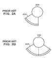
- FIG. 2A shows a drive gear 202 of a ball cam mechanism 200 which changes clutch pressing force merely by rotation toward the H-position side of an auxiliary transmission mechanism.
- FIG. 2B shows a drive gear 204 of a ball cam mechanism 200 which changes clutch pressing force for both the H position and the L position, wherein there is a problem that the size of the gear part and the weight thereof are increased, and cost is also increased. In addition, there is also a problem that the gear part cannot be accommodated in a case.
- a driving force distribution apparatus for a four-wheel-drive vehicle which is capable of independently controlling shift switching control of an auxiliary transmission mechanism and control of pressing force of a friction clutch by one motor without mutual interference therebetween and realizes reduction in size, weight, and cost.
- Te present invention provides a four-wheel-drive-vehicle driving force distribution apparatus. More specifically, in the present invention, a four-wheel-drive-vehicle driving force distribution apparatus having an auxiliary transmission mechanism for switching motive power transmitted to an input shaft at least between two levels, a high speed and a low speed, and transmitting the motive power to a main output shaft and a friction clutch for selectively transmitting the motive power of the main output shaft to an auxiliary output shaft, is characterized by having:
- the clutch control mechanism a drive projection is formed on an end surface of the drive member in the pinion gear-side, a driven projection is formed on an end face of the pinion gear in the drive member-side, the drive projection is caused to abut the driven projection by rotation of the drive member in the first direction from the control starting point and rotate the pinion gear in the first direction, and the pinion gear is rotated to return by reaction force of the friction clutch in return rotation of the drive member to the control starting point.
- the shift control mechanism has a ratchet attached to the drive member and a ratchet groove formed on an end face of the shifting cylindrical cam in the drive member-side; wherein, in forward rotation of the drive member in the second direction, the ratchet is engaged with the ratchet groove so as to rotate the shifting cylindrical cam and switch a current shift position to a next shift position; and, in return rotation, the ratchet is removed from the ratchet groove so as to return the drive member to the control starting point while the shifting cylindrical cam remains at the position.
- the shift control mechanism has a shutter member for housing the ratchet so as to prevent engagement between the ratchet and the ratchet groove when the drive member is rotated in the first direction so as to operate the clutch control mechanism.
- the ratchet groove is provided at N locations at an angle interval of ⁇ which is 360° divided by the number of switching levels N starting from the control starting point, and an outer peripheral cam groove for changing a shift position by the interval angle ⁇ is formed on the outer periphery of the shifting cylindrical cam.
- two ratchet grooves are provided on an end face of the shifting cylindrical cam at an interval of 180° starting from the control starting point, and an outer peripheral cam groove for changing a high-speed shift position and a low-speed shift position is formed on the outer periphery of the shifting cylindrical cam at an interval of 180°.
- Another embodiment of the shift control mechanism has a slide key attached to the drive member and retained at a retracted position by a built-in spring; an engagement groove which is formed on the end face of the shifting cylindrical cam in the drive member-side and to be engaged with the slide key; and a shift control plate for, in forward rotation of the drive member in the second direction, pressing a rear portion of the slide key so as to rotate the shifting cylindrical cam in the state in which a distal end of the key is engaged with the engagement groove so as to switch a current shift position to a next shift position; causing the slide key to return to the retracted position at the next shift position and causing merely the drive member to return to the control starting point in the state in which the slide key is removed from the slide groove; and, when the drive member is to be returned to the control starting point during the forward rotation to the next shift position, causing the shifting cylindrical cam to return to the control starting point in the state in which engagement between the slide key and the engagement groove is maintained.
- the engagement groove is provided at N locations at an angle interval of ⁇ which is 360° divided by the number of switching levels N starting from the control starting point, and an outer peripheral cam groove for changing a shift position by the interval angle ⁇ is formed on the outer periphery of the shifting cylindrical cam.
- the number of switching levels of the auxiliary transmission mechanism is two, high and low, two engagement grooves are provided on an end face of the shifting cylindrical cam at an interval of 180° starting from the control starting point, and an outer peripheral cam groove for changing a high-speed shift position and a low-speed shift position is formed on the outer periphery of the shifting cylindrical cam at an interval of 180°.
- the shift mechanism has a shift waiting mechanism between the shift control mechanism and the shift mechanism.
- switching of the auxiliary transmission mechanism and torque control of the friction clutch can be performed by one motor without using an electrical switching means such as an electromagnetic clutch; therefore, cost can be reduced compared with the cases in which motors are separately provided for shifting of the auxiliary transmission mechanism and torque control of the friction clutch.
- the pressing force of the friction clutch can be changed by the rotation in one direction, for example, clockwise rotation with respect to the control starting point, and high/low switching of the auxiliary transmission mechanism can be performed, for example, by counterclockwise reciprocating rotation. Therefore, even though they are driven by the same motor, the shift control and the torque control of the friction clutch can be independently performed depending on the rotation directions, and optimal control conditions can be individually determined.
- the waiting mechanism is provided in the shift mechanism of the auxiliary transmission mechanism, the shifting operation can be completed even when meshing phases of the clutch gears are misaligned.
- torque of the friction clutch can be controlled by changing the rotation direction, and the driving gear of the ball cam mechanism is always used in the rotation of one direction by the pinion gear. Therefore, reduction in size and weight can be realized, and cost is also reduced.
- third and fourth positions such as neutral and 4WD lock can be readily set.
- FIG. 3 is a cross sectional view showing an embodiment of a four-wheel-drive-vehicle driving force distribution apparatus according to the present invention.
- the four-wheel-drive-vehicle driving force distribution apparatus of the present embodiment has a case 10, an input shaft 12 which inputs motive power from an engine to the left side of the case 10 via an automatic transmission or a manual transmission is provided, and the input shaft 12 is coupled to a rear-wheel output shaft 24, which is coaxially disposed and serving as a main output shaft, via an auxiliary transmission mechanism 14.
- the auxiliary transmission mechanism 14 is a planetary gear mechanism having a sun gear 16, a planetary gear 18 provided on a carrier case 20, and a ring gear 22.
- a clutch gear 54 is provided integrally with the carrier case 20, and, corresponding to that, a shift gear 52 which can perform shift operation is disposed.
- the auxiliary transmission mechanism 14 performs switching between a H position and a L position.
- the shift gear 52 is at the position shown in the drawing, the H position is attained, and the sun gear 16 is directly connected to the rear-wheel output shaft 24.
- the position at which the shift gear 52 is meshed with the clutch gear 54 is the L position, wherein the ring gear 22 is fixed, and the input rotation of the sun gear 16 is transmitted to the rear-wheel output shaft 24 via the clutch gear 54 and then the shift gear 52 as rotation of the carrier case 20 having the planetary gear 18.
- a friction clutch 26 is provided coaxially with the rear-wheel output shaft 24.
- the friction clutch 26 fixes a clutch hub 44 to the rear-wheel output shaft 24 and couples a clutch drum 46 to a sprocket gear 25 which is rotatably provided with respect to the rear-wheel output shaft 24.
- a front-wheel output shaft 30 serving as an auxiliary output shaft which outputs motive power to the other side is provided on the case 10
- a sprocket gear 31 is integrally formed with the front-wheel output shaft 30, and a chain belt 28 is wound around the gear and the sprocket gear 25 of the friction clutch 26 side so as to couple them.
- a multi-plate clutch 48 provided between the clutch hub 44 and the clutch drum 46 of the friction clutch 26 is separated, and the rotation of the input shaft 12 is transmitted to the rear-wheel output shaft 24 via the auxiliary transmission mechanism 14.
- the friction clutch 26 attains a connected state, and the motive power from the input shaft 12 is also transmitted to the front-wheel output shaft 30 via the rear-wheel output shaft 24, the friction clutch 26, the sprocket gear 25, the chain belt 28, and the sprocket gear 31.
- a ball cam mechanism 32 which controls the clutch pressing force (transmitted torque) of the multi-plate clutch 48 provided between the clutch hub 44 and the clutch drum 46 in a non-step manner is provided.
- the ball cam mechanism 32 retains balls 38 sandwiched between ball cam grooves 39 of opposing cam surfaces of a fixed cam plate 34 and a rotating cam plate 36 which are provided coaxially with the rear-wheel output shaft 24.
- the fixed cam plate 34 has an arm portion 37 extended toward a motor output shaft 72, wherein a U-shaped distal end thereof is engaged with the outside of a bearing 77 so as to stop rotation.
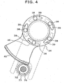
- the rotating cam plate 36 has a drive gear 40 extended toward the motor output shaft 72 and engaged with a pinion gear 76, and the drive gear 40 has a sector-like end face shape.
- a fixed plate 35 is disposed in the right side of the fixed cam plate 34 via a thrust bearing, and a pressing member 42 is disposed in the left side of the rotating cam plate 36 via a thrust bearing.
- a motor 70 is provided as a drive source which controls a shift mechanism 50 of the auxiliary transmission mechanism 14 and the pressing force of the friction clutch 26.
- the motor 70 transmits the rotation generated by a built-in reduction gear to the motor output shaft 72.
- a drive member 74, a pinion gear 76, and a shifting cylindrical cam 78 which constitute the clutch control mechanism of the friction clutch 26 and the shift control mechanism of the auxiliary transmission mechanism 14, which will be elucidated in the below description, are disposed coaxially on the motor output shaft 72.
- the drive member 74 is fixed to the motor output shaft 72, and, with respect that, the pinion gear 76 and the shifting cylindrical cam 78 are relatively-rotatably attached to the motor output shaft 72.
- the drive member 74 is not coupled to the pinion gear 76 and the shifting cylindrical cam 78.
- a shift pin 82 is guided and moved in the axial direction by a shifting cam groove 96 formed on the outer periphery thereof, and, for example, the shift pin 82 is moved from the shown H position in the auxiliary transmission mechanism 14 toward right so as to perform switch to the L position.
- the shift operation which is caused by the rotation of the shifting cylindrical cam 78 along with the counterclockwise rotation of the drive member 74, one shift operation is completed when the drive member 74 is rotated in the opposite direction to return to the control starting point after the switching to the shift position is completed.
- the shifting cylindrical cam 78 Upon the return from the shift position, the shifting cylindrical cam 78 remains at the shift switched position, and merely the drive member 74 is rotated to return to the control starting point.
- a waiting mechanism 60 is provided between the shift pin 82, which is shifted in the axial direction by the shifting cylindrical cam 78, and a shift fork 56.
- the waiting mechanism 60 is disposed in the right side of the shift fork 56, which is fixed to a shift rod 58, and a stopper ring 64 is inserted in the right side of a built-in spring 62 so as to fix it.
- the waiting mechanism 60 compresses the spring 62 by a shift operation of the shift pin 82, thereby attaining a waiting state in which the shift fork 56 is energized in the shift direction by the force of the spring 62.
- a shift operation is performed by the force of the spring 62 so that the shift operation per se can be completed even when the gears are not meshed with each other.
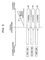
- FIG. 5 is an explanatory diagram of the clutch control and the shift control with respect to the rotation directions of the motor output shaft 72 in the embodiment of FIG. 3 .
- the motor output shaft 72 is positioned at the control starting point as an initial state, and clockwise rotation or counterclockwise rotation is performed with respect to the control starting point.
- the clutch control is performed by rotating the motor output shaft clockwise starting from the control starting point.
- the ball cam mechanism 32 operates, and, as shown by a clutch control characteristic 81, the pressing force of the friction clutch 26 is increased in a non-step manner corresponding to the amount of rotation.
- the motor output shaft 72 is rotated counterclockwise starting from the control starting point.
- control characteristics optimal for each of the control can be readily set.
- the control of the friction clutch 26 can be performed merely by changing the rotation directions to the opposite even when the shift mechanism is either at the L position or the H position, and the control of the friction clutch can be performed by the rotation in merely one direction. Therefore, as shown in FIG. 2A , the size of the drive gear 40 may be that corresponding to one-side shift, and the size and the weight of the drive gear 40 used in the present invention can be reduced compared with the conventional drive gear of FIG. 2B , in which the H position and the L position are determined by the rotation directions and clutch control is respectively performed, thereby reducing the cost.
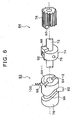
- FIG. 6 is an explanatory drawing showing the shift control mechanism and the clutch control mechanism in the embodiment of FIG. 3 in an exploded manner.
- the clutch control mechanism 84 comprises a drive projection 88 provided on the drive member 74 which is fixed to the motor output shaft 72 by a fixed pin 75 and a driven projection 90 provided on the pinion gear 76 which is rotatably disposed on the motor output shaft 72.
- the driven projection 90 of the pinion gear 76 is in the non-driven state in which the end face thereof is not in contact with that of the drive projection 88 of the drive member 74.
- the shift control mechanism 83 comprises a ratchet 92 provided on the drive member 74 and the shifting cylindrical cam 78 which is rotatably provided on the motor output shaft 72.
- the ratchet 92 provided on the drive member 74 is pushed by a spring and incorporated in an axial-direction groove on the outer peripheral side thereof, and an edge-like claw portion at the distal end thereof protrudes to the outside.
- ratchet grooves 94-1 and 94-2 are formed at two locations on the end face thereof in the drive member 74-side.
- the shifting cam groove 96 is formed on the outer periphery of the shifting cylindrical cam 78.
- the shifting cam groove 96 converts the rotation of the shifting cylindrical cam 78 into linear shift motion in the axial direction of the shift pin 82, which is guided by the shifting cam groove 96.
- a check ball 98 pressed by a spring 100 is provided on the shifting cylindrical cam 78.
- Check grooves in which the check balls 98 are engaged in are provided at two locations which are shift positions determined by the ratchet grooves 94-1 and 94-2, and the switching positions of the H position and the L position are positioned by the engagement of the check ball 98 with the check grooves.
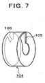
- FIG. 7 is an explanatory drawing of a shutter member which is attached to the shift control mechanism 83 of FIG. 6 .
- the ratchet 92 is projecting due to the spring. Therefore, although there is no problem in the clockwise rotation since the ratchet passes the ratchet grooves 94-1 and 94-2, in counterclockwise rotation in which the drive member 74 is to be returned to the control starting point, if the ratchet 92 is engaged in the ratchet groove 94-1 or 94-2, the shifting cylindrical cam 78 is erroneously rotated.
- the shutter member 104 is provided in order to prevent the engagement of the ratchet 92 with the ratchet grooves 94-1 and 94-2 upon rotation of the drive member 74, which is required in control of the clutch control mechanism.
- the shutter member 104 is attached and fixed to the pinion gear 76 of FIG. 6 and rotatably houses the drive member 74 in the inside thereof.
- the ratchet 92 is moved to the inside of the shutter 106 by the movement during the period in which the drive member 74 is rotated clockwise until the drive projection 88 abuts the driven projection 90 of the pinion gear 76; consequently, the ratchet is pushed to the inside of the drive member 74.
- FIG. 8 is an explanatory drawing of an assembled state of the clutch control mechanism 84 and the shift control mechanism 83 of FIG.6 .
- the axial direction of the motor output shaft 72 is the vertical direction of the sheet, and the pinion gear 76, the drive member 74, and the shifting cylindrical cam 78 are disposed in the axial direction sequentially from the side in which the motor is positioned.
- the drive member 74 is positioned between the pinion gear 76 and the shifting cylindrical cam 78 and fixed to the motor output shaft 72, which is not shown.
- the drive projection 88 is provided on the end face of the drive member 74 in the pinion gear 76-side, and, corresponding to that, the driven projection 90 is provided on the pinion gear 76.
- the shifting cam groove 96 On the outer periphery surface of the shifting cylindrical cam 78, the shifting cam groove 96 is formed, and the shift pin 82 is movably engaged therein.
- the check ball 98 receives the pressing force of the spring 100 and is attached to and engaged with the check groove 102-1 of the shifting cylindrical cam 78.
- the position of the shift pin 82 thereat is the control starting point in the shift control mechanism 86, and the shift position is, for example, at the H position.
- two check grooves 102-2 positioned on both sides of the check groove 102-1 is originally the same one, they are separately shown as a developed drawing.
- the shutter member 104 is fixed by engaging an engagement notch 105 with the driven projection 90 of the pinion gear 76 as shown in FIG.7 , and the member is disposed and fixed so that, at the shown position of the control starting point, the shutter 106 formed on the end face that is in the opposite side of the shutter member 104 is positioned in the right side of the ratchet 92 provided on the drive member.
- FIGs. 9A and 9B are explanatory drawings of clutch control in FIG. 8 .
- FIG. 9A shows the state of the control starting point that is same as FIG. 8 , and the shift pin 82 is, for example, at the H position at this control starting point.
- the motor output shaft is rotated clockwise by the motor.
- the drive member 74 is moved toward the right in the shown development drawing.
- the drive projection 88 abuts the driven projection 90 and rotates the pinion gear 76 clockwise, and the ball cam mechanism 32 is operated via the drive gear 40 shown in FIG. 3 .
- FIG. 9B shows the state of clutch control.
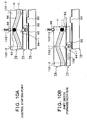
- FIGs. 10A to 10D are explanatory drawings of shift control in the embodiment of FIG. 8 .
- FIG. 10A shows the control starting point, and the shift pin 82 is positioned at the H position in this example.
- the drive member 74 is rotated counterclockwise by the motor output shaft. By the counterclockwise rotation, the drive member 74 is moved toward the left in the shown development drawing.
- FIG. 10B shows forward rotation of shift switching in which the drive member 74 is rotated counterclockwise as shown by an arrow 108, wherein the ratchet 92 provided on the drive member 74 is integrally rotated in the state in which the ratchet is engaged with the ratchet groove 94-1 of the shifting cylindrical cam 78.
- FIG. 10D shows shift switch end, wherein the drive member 74 is returned to the control starting point, and the ratchet 92 of the drive member 74 is engaged with the next ratchet groove 94-2.
- the drive member 74 is rotated forward counterclockwise again as shown in FIG. 10B after the shift switch end of FIG. 10D and subsequently rotated backward as shown in FIG. 10C , it is switched from the L position the original H position and returned to the starting position again in the return rotation.
- the clutch control mechanism and the shift control mechanism of FIG. 8 when the shift operation is stopped and the drive member 74 is returned to the control starting point before the forward rotation for shift switching from the control starting point of FIG. 10A to FIG.
- the shifting cylindrical cam 78 remains at an intermediate position at which the rotation direction is switched and does not return to the control starting point. Therefore, in the present embodiment, for the shift switching performed by counterclockwise rotation of the drive member 74, interlocking has to be mechanically or electrically performed so that shifting can be cancelled when 180° counterclockwise rotation and 180° return rotation thereafter is completed without stopping the rotation in the middle of the range of 180° by motor drive.
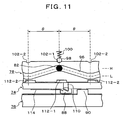
- FIG. 11 is another embodiment of the shift control mechanism and the clutch control mechanism of FIG. 3 , and this embodiment is characterized in that the shifting cylindrical cam 78 is returned to the control starting point when shifting is cancelled during counterclockwise rotation which is caused along with shift control.
- the pinion gear 76 and the shifting cylindrical cam 78 are rotatably disposed in both sides of the drive member 74, which is fixed to the motor output shaft.
- the drive projection 88 is provided on the drive member 74, and, corresponding to that, the driven projection 90 is provided on the pinion gear 76.
- a slide key 110 is provided slidably in the axial direction, and the slide key 110 is retained at a shown initial position by a built-in spring.
- the shifting cam groove 96 is formed on the outer periphery of the shifting cylindrical cam 78, the shift pin 82 is guidably engaged therein, and the check grooves 102-1 and 102-2 are provided at two locations corresponding to the shift positions.
- the check ball 98 is engaged with the check groove 102-1, which is serving as the H position, by the spring 100.
- engagement grooves 112-1 and 112-2 are formed, and the slide key 110 is at a position away from the engagement groove 112-1 at the shown control starting point.
- a shift control plate 114 fixed to the pinion gear 76-side is provided for the drive member 74.
- a portion of the shift control plate 114 is positioned on an end face portion of the drive member 74, and the plate has a structure that can cause the shifting cylindrical cam 78 to return to the control starting point when it is to be returned during a shift operation by guiding the slide key 110 by using the inside and outside of the shift control plate 114 with respect to counterclockwise rotation of the drive member 74 for shift control.
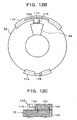
- FIGs. 12A to 12C are explanatory drawings showing details of the slide key 110 and the shift control plate 114.
- FIG. 12A is an enlarged view of the shift slide key 110 of the drive member 74 and the shift control plate 114 provided in the pinion gear 76-side.
- the slide key 110 is retained at a shown neutral position by the built-in spring 120 and is extended or retracted when it is guided by the shift control plate 114.
- a guide portion 122 which is outwardly bent at the distal end of the shown control starting point is provided in the shift control plate 114.
- FIG. 12B shows the end face of the drive member 74 together with a part of the shift control plate 114.
- the slide key 110 is incorporated in a key groove 115 provided on the outer periphery of the drive member 74 so as to be movable in the axial direction.
- the guide portion 122 of the shift control plate 114 is positioned to be outwardly projected in the left side of the slide key 110, and, when the drive member 74 is rotated counterclockwise, the slide key 110 is pushed in along with the guide portion 122.
- FIG. 12C shows a cross sectional structure of the slide key 110 with respect to the drive member 74, wherein an escape groove 118 is formed in the back of the key distal end 116-side in the slide key 110.
- a spring housing portion 124 is formed in the key groove 115-side of the drive member 74, and a spring housing portion 126 is also formed in the slide key 110-side.
- the spring 120 is incorporated in the spring housing portions 124 and 126 formed by a combination of them.
- the slide key 110 is moved when receiving pressing force in the left or right direction; however, by virtue of incorporation of the spring 120, it is returned to the shown initial position determined by the spring 120 when the pressing force is released.
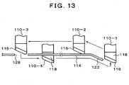
- FIG. 13 is an explanatory drawing showing movement along with the shift control of the slide key 110 with respect to the shift control plate 114 of FIGs. 12A to 12C .
- the drive member 74 is omitted, and movement of the slide key 110 caused along with counterclockwise rotation and return rotation of the drive member 74 is shown separately in four stages of slide keys 110-1 to 110-4.
- the slide key is at the position shown by the slide key 110-1.
- the key distal end 116 abuts the guide portion 122 of the shift control plate 114, and the slide key is moved to the position of the slide key 110-2 along the guide portion 122.
- the slide key 110-1 is pushed into the key groove of the drive member 74, and the other side is engaged in the engagement groove 112-1 of the shifting cylindrical cam 78 shown in FIG. 12A . Furthermore, when the drive member 74 is rotated, the slide key is moved from the position of the slide key 110-2 to that of the slide key 110-3. This position is a shift switched position, and the opening 128 is provided in the shift control plate 114 at the shift switched position; therefore, the slide key 110-3 is caused to return to the initial position same as the slide key 110-1 via the opening 128 by the force of the spring. When the key distal end 116 of the slide key 110-3 is projected through the opening 128, the shift control plate 114 is positioned at the part of the escape groove 118 in the back thereof.
- FIGs. 14A to 14C are explanatory drawings of clutch control in the embodiment of FIG. 11 .
- FIG. 14A shows a control starting point.
- the drive projection 88 of the drive member 74 abuts the driven projection 90 of the pinion gear 76 as shown in FIG. 14B , and the pinion gear 76 is rotated clockwise, thereby increasing the clutch pressing force.
- the clutch pressing force can be increased by clockwise rotation, or the clutch pressing force can be reduced by counterclockwise rotation.
- FIGs. 15A to 15F are explanatory drawings of shift control in the embodiment of FIG. 11 .
- FIG. 15A shows a control starting point, wherein the shift pin 82 is at the H position.
- the drive member 74 is driven counterclockwise in this state, forward rotation is performed like FIG. 15B as shown by an arrow 134.
- the slide key 110 is pushed in by guiding of the shift control plate 114, and the opposite side thereof is engaged with the engagement groove 112-1 of the shifting cylindrical cam 78. Consequently, the shifting cylindrical cam 78 rotated counterclockwise integrally with the drive member 74, and guiding by the shifting cam 96 causes the shift pin 82 to begin to move from the H position to the L position.
- FIG. 15A shows a control starting point, wherein the shift pin 82 is at the H position.
- FIG. 15C shows reach to a shift position, wherein the shift pin 82 is moved to the L position which is determined by attachment and engagement of the check ball 98 with respect to the check groove 102-2.
- the slide key 110 is projected from the opening of the shift control plate 114 and returned to the initial position, wherein engagement with the engagement groove 102-1 is cancelled.
- FIG. 15D when return rotation of return from the shift position to the control starting point is performed like an arrow 136, the slide key 110 returns to the control starting point in the state in which the shift control plate 114 is positioned in the part of the back escape groove 118 as shown by the slide key 110-4 of FIG. 13 .
- 15E shows the state of the return rotation that is during return to the control starting point, wherein the slide key 110 moves over the guide portion 122 (see FIGs. 12A to 12C ), which is formed to be bent at the distal end side of the shift control plate 114 and projects. Then, it returns to the initial position again as shown in FIG. 15F and returns to the state of the control starting point, in other words, the initial position of the slide key same as that of FIG. 15A , wherein the shift pin at this point is switched to the L position.
- FIGs. 16A to 16E are explanatory drawings of shift control of the case in which the drive shaft is returned during shift in the embodiment of FIG. 11 .
- FIG. 16A shows a control starting point.
- the drive member 74 is rotated counterclockwise in this state to perform forward rotation, the state of FIG. 16B is attained.
- the drive member is further rotated, the state of FIG. 16C is attained.
- the shift is cancelled during the forward rotation of FIG.
- the shifting cylindrical cam 78 since the engaged state with the engagement groove 112-1 of the shifting cylindrical cam 78 is maintained by virtue of the push-in of the slide key 110 along the shift control plate 114, the shifting cylindrical cam 78 also returns to the starting position along with the return rotation of the drive member 74, and, via the position immediately before the check ball 98 is engaged with the check groove 102-1 like FIG. 16E , the state of the control starting point of FIG. 16A is attained again. In such embodiment of FIG. 11 , the shifting cylindrical cam can be returned in conjunction with the movement of the drive member 74 even when shifting is cancelled during the shifting.
- shift cancelling control can be appropriately performed by the motor operated in conjunction with a shift cancelling operation during the shift operation.
- the above described embodiments take the two-level switching between the H position and the L position as an example as an auxiliary transmission mechanism.
- switching positions in the auxiliary transmission mechanism furthermore, addition in the positions, for example, a third position and a fourth position such as neutral and 4WD lock may be readily set.
- the clutch control can be independently performed by an arbitrary rotation angle, for example, in clockwise rotation for the clutch control.
- a ratchet key comprising the ratchet 92 and the ratchet grooves 94-1 and 94-2 is provided in the shift control mechanism 86.
- the mechanism may have a structure using a so-called ratchet which is a ratchet rotated by a pin as the ratchet 92 instead of the slide structure.
- ratchet which is a ratchet rotated by a pin as the ratchet 92 instead of the slide structure.
- the present invention includes arbitrary modifications that do not impair the object and advantages thereof and is not limited by the numerical values shown in the above described embodiments.
Landscapes
- Engineering & Computer Science (AREA)
- Mechanical Engineering (AREA)
- Chemical & Material Sciences (AREA)
- Combustion & Propulsion (AREA)
- Transportation (AREA)
- General Engineering & Computer Science (AREA)
- Arrangement And Driving Of Transmission Devices (AREA)
Claims (8)
- Antriebskraftverteilungsvorrichtung für ein Fahrzeug mit Vierradantrieb
mit einem Hilfsübertragungsmechanismus (14) zum Umschalten der an eine Eingangwelle (12) übertragenen Antriebsleistung zwischen wenigstens zwei Stufen, einer hohen Geschwindigkeit und einer niedrigen Geschwindigkeit, und zum Übertragen der Antriebsleistung auf eine Hauptausgangswelle (24) und
mit einer Reibungskupplung (26) zum selektiven Übertragen der Antriebsleistung der Hauptausgangswelle auf eine Hilfsausgangswelle (30),
wobei die Antriebskraftverteilungsvorrichtung für das Fahrzeug mit Vierradantrieb auweist:einen Motor (70),einen Kugelnockenmechanismus (32) zum stufenlosen Ändern der Andruckkaft der Reibungskupplung nach Maßgabe der Drehung eines Zahnritzels (76), das drehbar und koaxial auf einer Ausgangswelle (72) des Motors angeordnet ist,einen Schiebemechanismus (50) zur Umwandlung der Drehung eines verschiebbaren Zylindernockens (78), der drehbar und koaxial auf der Ausgangswelle des Motors angeordnet ist, in eine lineare Schiebebewegung und zum Verschieben des Hilfsübertragungsmechanismus,ein auf der Ausgangswelle des Motors fixiertes Antriebsglied (74),einen zwischen dem Antriebsglied und dem Zahnritzel angeordneten Kupplungssteuerungsmechanismus (84) zum Ändern des von dem Kugelnockenmechanismus erzeugten Kupplungsanpressdrucks nach Maßgabe der in einem Steuerungsstartpunkt beginnenden von dem Motor bewirkten Drehung des Antriebsglieds in einer ersten Richtungund einen zwischen dem Antriebsglied und dem verschiebbaren Zylindernocken angeordneten Schiebesteuerungsmechanismus (83),dadurch gekennzeichnet,dass dieser eine Übertragung des Hilfsübertragungsmechanismus in eine gegebene Verschiebungsposition in einer bestimmten Reihenfolge wiederholt, wenn er von dem Motor in einer Wechselbewegung eine vorbestimmte Anzahl von Malen bis zur Vollendung der Umschaltung in eine Verschiebungsposition in der zweiten Richtung gedreht und in den Steuerungsstartpunkt zurückgeführt wird. - Antriebskraftverteilungsvorrichtung für ein Fahrzeug mit Vierradantrieb nach Anspruch 1, bei dem
in dem Kupplungssteuerungsmechanismus
in einer Stirnfläche des Antriebsglieds auf der Seite des Zahnritzels ein Antriebsvorsprung (88) ausgebildet ist, in einer Stirnfläche des Zahnritzels auf der Seite des Antriebsglieds ein angetriebener Vorsprung (90) ausgebildet ist, der Antriebsvorsprung durch eine von dem Steuerungsstartpunkt aus erfolgende Drehung in der ersten Richtung an dem angetriebenen Vorsprung zum Anschlag gebracht wird und das Zahnritzel bei der Rückwärtsdrehung des Antriebsglieds in den Steuerungsstartpunkt durch die Reaktionskraft der Reibungskupplung zurückgedreht wird. - Antriebskraftverteilungsvorrichtung für ein Fahrzeug mit Vierradantrieb nach Anspruch 1,
bei der Schiebesteuerungsmechanismus aufweist:eine an dem Antriebsglied angebrachte Klinke (92) undeine in einer Stirnfläche des verschiebbaren Zylindernockens auf der Seite des Antriebsglieds ausgebildete Klinkennut (94-1, 94-1), wobeibei Vorwärtsdrehung des Antriebsglieds in der zweiten Richtung die Klinke mit der Klinkennut in Eingriff kommt, so daß sie den verschiebbaren Zylindernocken dreht und eine laufende Verschiebungsposition in eine nächste Verschiebungsposition umschaltet, und bei Rückwärtsdrehung die Klinke aus der Klinkennut entfernt wird, so daß das Antriebsglied in den Steuerungsstartpunkt zurückgeführt wird, während der verschiebbare Zylindernocken in der Position verbleibt. - Antriebskraftverteilungsvorrichtung für ein Fahrzeug mit Vierradantrieb nach Anspruch 1, bei der der Schiebesteuerungsmechanismus ein Verschlußglied (104) für die Aufnahme der Klinke aufweist, um den Eingriff zwischen der Klinke und der Klinkennut zu verhindern, wenn das Antriebsglied in der ersten Richtung gedreht wird, um den Kupplungssteuerungsmechanismus zu betätigen.
- Antriebskraftverteilungsvorrichtung für ein Fahrzeug mit Vierradantrieb nach Anspruch 1, bei der dann, wenn die Zahl der Schaltstufen des Hilfsübertragungsmechanismus gleich N ist, die Klinkennut, beginnend an dem Steuerungsstartpunkt, an dem verschiebbaren Zylindernocken an N Stellen mit einem Winkelabstand θ vorgesehen ist, mit θ gleich 360°, dividiert durch die Zahl N der Schaltstufen, und wobei auf dem Aussenumfang des verschiebbaren Zylindernockens eine äussere periphere Nockennut (96) zur Änderung der Verschiebungsposition um den Winkelabstand θ ausgebildet ist.
- Antriebskraftverteilungsvorrichtung für ein Fahrzeug mit Vierradantrieb nach Anspruch 1, bei der der Schiebesteuerungsmechanismus aufweist:einen Gleitkeil (110), der an dem Antriebsglied angebracht ist und von einer eingebauten Feder (120) in einer zurückgezogenen Stellung gehalten wird,eine Eingriffsnut (112), die in der Stirnfläche des verschiebbaren Zylindernockens auf der Seite des Antriebsglieds ausgebildet ist und mit dem Gleitkeil in Eingriff bringbar ist, undeine Schiebesteuerplatte (114), um bei Vorwärtsdrehung des Antriebsglieds in der zweiten Richtung gegen den hinteren Teil des Gleitkeils zu drücken und den verschiebbaren Zylindernocken in dem Zustand, in welchem das distale Ende des Keils mit der Eingriffsnut in Eingriff steht, zu drehen, um aus einer laufenden Verschiebungsposition in eine nächste Verschiebungsposition umzuschalten, zu bewirken, dass der Gleitkeil in der nächsten Verschiebungsposition in die zurückgezogene Stellung zurückkehrt und zu bewirken, dass in dem Zustand, in dem der Gleitkeil aus der Eingriffsnut entfernt ist, nur das Antriebsglied in den Steuerungsstartpunkt zurückkehrt, und wenn das Antriebsglied während der Vorwärtsdrehung zur nächsten Verschiebungsposition zu dem Steuerungsstartpunkt zurückgeführt werden soll, zu bewirken, dass der verschiebbare Zylindernocken in dem Zustand, in welchem der Eingriff zwischen dem Gleitkeil und der Eingriffsnut beibehalten wird, in den Steuerungsstartpunkt zurückkehrt.
- Antriebskraftverteilungsvorrichtung für ein Fahrzeug mit Vierradantrieb nach Anspruch 6, bei der dann, wenn die Zahl der Schaltstufen des Hilfsübertragungsmechanismus gleich N ist, die Eingriffsnut, beginnend an dem Steuerungsstartpunkt, an dem verschiebbaren Zylindernocken an N Stellen mit einem Winkelabstand θ vorgesehen ist, mit θ gleich 360°, dividiert durch die Zahl N der Schaltstufen, und wobei auf dem Aussenumfang des verschiebbaren Zylindernockens eine äussere periphere Nockennut (96) zur Änderung der Verschiebungsposition um den Winkelabstand θ ausgebildet ist.
- Antriebskraftverteilungsvorrichtung für ein Fahrzeug mit Vierradantrieb nach Anspruch 1, bei der der Schiebemechanismus zwischen dem Schiebesteuerungsmechanismus und dem Schiebemechanismus einen Verschiebungsverzögerungsmechanismus (60) aufweist.
Priority Applications (2)
| Application Number | Priority Date | Filing Date | Title |
|---|---|---|---|
| EP20070009952 EP1995106B1 (de) | 2007-05-18 | 2007-05-18 | Vorrichtung für Kräfteverteilung bei einem Allradfahrzeug |
| DE200760005936 DE602007005936D1 (de) | 2007-05-18 | 2007-05-18 | Vorrichtung für Kräfteverteilung bei einem Allradfahrzeug |
Applications Claiming Priority (1)
| Application Number | Priority Date | Filing Date | Title |
|---|---|---|---|
| EP20070009952 EP1995106B1 (de) | 2007-05-18 | 2007-05-18 | Vorrichtung für Kräfteverteilung bei einem Allradfahrzeug |
Publications (2)
| Publication Number | Publication Date |
|---|---|
| EP1995106A1 EP1995106A1 (de) | 2008-11-26 |
| EP1995106B1 true EP1995106B1 (de) | 2010-04-14 |
Family
ID=38542986
Family Applications (1)
| Application Number | Title | Priority Date | Filing Date |
|---|---|---|---|
| EP20070009952 Ceased EP1995106B1 (de) | 2007-05-18 | 2007-05-18 | Vorrichtung für Kräfteverteilung bei einem Allradfahrzeug |
Country Status (2)
| Country | Link |
|---|---|
| EP (1) | EP1995106B1 (de) |
| DE (1) | DE602007005936D1 (de) |
Families Citing this family (2)
| Publication number | Priority date | Publication date | Assignee | Title |
|---|---|---|---|---|
| DE102012003482A1 (de) * | 2012-02-21 | 2013-08-22 | Audi Ag | Schaltvorrichtung für ein Antriebssystem für allradgetriebene Kraftfahrzeuge |
| EP2837852B1 (de) | 2013-08-01 | 2016-03-23 | GM Global Technology Operations LLC | Schaltanordnung mit einer Kupplungs- und Synchronisierungseinrichtung für ein Getriebe |
Family Cites Families (4)
| Publication number | Priority date | Publication date | Assignee | Title |
|---|---|---|---|---|
| DE10058198A1 (de) | 2000-11-23 | 2002-06-27 | Zahnradfabrik Friedrichshafen | Allradverteilergetriebe für ein Kraftfahrzeug |
| US6645109B2 (en) | 2001-03-27 | 2003-11-11 | New Venture Gear, Inc. | Two-speed transfer case with ball-ramp clutch and single motor activator/shift system |
| US6802794B2 (en) | 2003-02-21 | 2004-10-12 | Borgwarner, Inc. | Single actuator lost motion shift assembly |
| US6929577B2 (en) * | 2003-11-24 | 2005-08-16 | Magna Drivetrain Of America, Inc. | Clutch actuation system for two-speed active transfer case |
-
2007
- 2007-05-18 DE DE200760005936 patent/DE602007005936D1/de active Active
- 2007-05-18 EP EP20070009952 patent/EP1995106B1/de not_active Ceased
Also Published As
| Publication number | Publication date |
|---|---|
| DE602007005936D1 (de) | 2010-05-27 |
| EP1995106A1 (de) | 2008-11-26 |
Similar Documents
| Publication | Publication Date | Title |
|---|---|---|
| US8037984B2 (en) | Four-wheel-drive-vehicle driving force distribution apparatus | |
| US5339908A (en) | Power tool | |
| US20180328487A1 (en) | Shift-drum speed change operation mechanism | |
| EP2447103B1 (de) | Vorrichtung zur verteilung einer antriebskraft | |
| US20110226079A1 (en) | Actuating device with shift carrage lock | |
| US11614165B2 (en) | Shift-drum speed change operation mechanism | |
| JP5549877B2 (ja) | 負荷感応型変速装置 | |
| CN111043262B (zh) | 用于车辆的动力传动系 | |
| WO2019189006A1 (ja) | 変速機構 | |
| JP2011185398A (ja) | 変速機駆動装置 | |
| EP1995106B1 (de) | Vorrichtung für Kräfteverteilung bei einem Allradfahrzeug | |
| EP3992495B1 (de) | Fahrzeuggetriebe | |
| CN111376716B (zh) | 用于车辆的分动器 | |
| JP3694945B2 (ja) | 変速装置 | |
| KR100456916B1 (ko) | 기어드 모터 | |
| US20070221432A1 (en) | Infinitely Variable Power Bypass Transmission With Two Operating Modes for a Motor Vehicle | |
| US11261964B2 (en) | Compliant shifting mechanism and multi-speed power tool having same | |
| JP2012096719A (ja) | 駆動力配分装置 | |
| JP5759326B2 (ja) | 四輪駆動車用駆動力配分装置 | |
| JP3610920B2 (ja) | 自動変速装置 | |
| JP2001349425A (ja) | 変速装置 | |
| JP2522642B2 (ja) | 自動二輪車等における後退装置 | |
| RU2060424C1 (ru) | Механизм переключения ступенчатой коробки передач | |
| KR102184464B1 (ko) | 부변속기 포크 구조 | |
| JPS645158Y2 (de) |
Legal Events
| Date | Code | Title | Description |
|---|---|---|---|
| PUAI | Public reference made under article 153(3) epc to a published international application that has entered the european phase |
Free format text: ORIGINAL CODE: 0009012 |
|
| AK | Designated contracting states |
Kind code of ref document: A1 Designated state(s): AT BE BG CH CY CZ DE DK EE ES FI FR GB GR HU IE IS IT LI LT LU LV MC MT NL PL PT RO SE SI SK TR |
|
| AX | Request for extension of the european patent |
Extension state: AL BA HR MK RS |
|
| 17P | Request for examination filed |
Effective date: 20081127 |
|
| 17Q | First examination report despatched |
Effective date: 20090113 |
|
| AKX | Designation fees paid |
Designated state(s): DE FR GB |
|
| GRAP | Despatch of communication of intention to grant a patent |
Free format text: ORIGINAL CODE: EPIDOSNIGR1 |
|
| GRAS | Grant fee paid |
Free format text: ORIGINAL CODE: EPIDOSNIGR3 |
|
| GRAA | (expected) grant |
Free format text: ORIGINAL CODE: 0009210 |
|
| AK | Designated contracting states |
Kind code of ref document: B1 Designated state(s): DE FR GB |
|
| REG | Reference to a national code |
Ref country code: GB Ref legal event code: FG4D |
|
| REF | Corresponds to: |
Ref document number: 602007005936 Country of ref document: DE Date of ref document: 20100527 Kind code of ref document: P |
|
| PLBE | No opposition filed within time limit |
Free format text: ORIGINAL CODE: 0009261 |
|
| STAA | Information on the status of an ep patent application or granted ep patent |
Free format text: STATUS: NO OPPOSITION FILED WITHIN TIME LIMIT |
|
| 26N | No opposition filed |
Effective date: 20110117 |
|
| REG | Reference to a national code |
Ref country code: FR Ref legal event code: PLFP Year of fee payment: 9 |
|
| REG | Reference to a national code |
Ref country code: FR Ref legal event code: PLFP Year of fee payment: 10 |
|
| REG | Reference to a national code |
Ref country code: FR Ref legal event code: PLFP Year of fee payment: 11 |
|
| REG | Reference to a national code |
Ref country code: FR Ref legal event code: PLFP Year of fee payment: 12 |
|
| PGFP | Annual fee paid to national office [announced via postgrant information from national office to epo] |
Ref country code: FR Payment date: 20210525 Year of fee payment: 15 Ref country code: DE Payment date: 20210520 Year of fee payment: 15 |
|
| PGFP | Annual fee paid to national office [announced via postgrant information from national office to epo] |
Ref country code: GB Payment date: 20210520 Year of fee payment: 15 |
|
| REG | Reference to a national code |
Ref country code: DE Ref legal event code: R119 Ref document number: 602007005936 Country of ref document: DE |
|
| GBPC | Gb: european patent ceased through non-payment of renewal fee |
Effective date: 20220518 |
|
| PG25 | Lapsed in a contracting state [announced via postgrant information from national office to epo] |
Ref country code: FR Free format text: LAPSE BECAUSE OF NON-PAYMENT OF DUE FEES Effective date: 20220531 |
|
| PG25 | Lapsed in a contracting state [announced via postgrant information from national office to epo] |
Ref country code: GB Free format text: LAPSE BECAUSE OF NON-PAYMENT OF DUE FEES Effective date: 20220518 Ref country code: DE Free format text: LAPSE BECAUSE OF NON-PAYMENT OF DUE FEES Effective date: 20221201 |