EP1995157A1 - Procédé et dispositif d'équilibrage longitudinal d'un véhicule agricole - Google Patents
Procédé et dispositif d'équilibrage longitudinal d'un véhicule agricole Download PDFInfo
- Publication number
- EP1995157A1 EP1995157A1 EP08102565A EP08102565A EP1995157A1 EP 1995157 A1 EP1995157 A1 EP 1995157A1 EP 08102565 A EP08102565 A EP 08102565A EP 08102565 A EP08102565 A EP 08102565A EP 1995157 A1 EP1995157 A1 EP 1995157A1
- Authority
- EP
- European Patent Office
- Prior art keywords
- agricultural vehicle
- ballast
- sensor means
- hydraulic
- vehicle
- Prior art date
- Legal status (The legal status is an assumption and is not a legal conclusion. Google has not performed a legal analysis and makes no representation as to the accuracy of the status listed.)
- Withdrawn
Links
- 238000000034 method Methods 0.000 title claims abstract description 15
- 230000000694 effects Effects 0.000 claims description 9
- 239000012530 fluid Substances 0.000 claims 2
- 230000035882 stress Effects 0.000 description 4
- 238000006073 displacement reaction Methods 0.000 description 3
- 238000001514 detection method Methods 0.000 description 2
- 230000000284 resting effect Effects 0.000 description 2
- 230000000087 stabilizing effect Effects 0.000 description 2
- 230000001010 compromised effect Effects 0.000 description 1
- 230000000368 destabilizing effect Effects 0.000 description 1
- 238000010586 diagram Methods 0.000 description 1
- 230000006355 external stress Effects 0.000 description 1
- 230000001771 impaired effect Effects 0.000 description 1
- 230000003068 static effect Effects 0.000 description 1
Images



Classifications
-
- B—PERFORMING OPERATIONS; TRANSPORTING
- B62—LAND VEHICLES FOR TRAVELLING OTHERWISE THAN ON RAILS
- B62D—MOTOR VEHICLES; TRAILERS
- B62D37/00—Stabilising vehicle bodies without controlling suspension arrangements
- B62D37/04—Stabilising vehicle bodies without controlling suspension arrangements by means of movable masses
Definitions
- the present invention relates to a method and device for longitudinally balancing an agricultural vehicle, in particular a tractor.
- loss of longitudinal stability may occur, for example, when a very heavy projecting implement is connected to a lift member of the vehicle.
- the weight of the vehicle alone may not be sufficient to counterbalance the tip-up moment produced when the implement, normally resting on the ground, is lifted off the ground.
- agricultural vehicles are equipped with ballast, connected integrally in a fixed position to the end of the vehicle opposite the implement end, to produce a stabilizing moment by which to counterbalance the tip-up moment produced by lifting the implement.
- the stabilizing moment produced by the ballast is constant and proportional to the weight of the ballast and its distance from the end of the vehicle, the effectiveness of the above known balancing system is seriously impaired by the fact that, for obvious reasons of size, the ballast must project as little as possible from the end of the vehicle, and also, the ballast must not be so heavy as to unnecessarily overload the vehicle in normal operating conditions.
- a device for balancing an agricultural vehicle in particular a tractor, as claimed in claim 10 and, preferably, in any one of the claims depending directly or indirectly on claim 10.
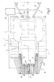
- Number 1 in the accompanying drawings indicates as a whole an agricultural vehicle, in particular a crawler tractor, which has a barycentric longitudinal axis 2, and comprises a frame 3, a body 4, and two known crawler traction devices 5 on opposite sides of axis 2.
- vehicle 1 At the rear longitudinal end, vehicle 1 comprises a known member 6 for attaching and lifting an implement 7 (shown by the dash line).
- member 6 comprises a fork 8 hinged to frame 3 and connectable removably to implement 7; and a known hydraulic cylinder 9 connected to a hydraulic circuit 10 of vehicle 1 and interposed between frame 3 and fork 8 to lift and lower fork 8 and implement 7 with respect to the ground in response to control by the operator.
- hydraulic circuit 10 comprises, in known manner, a pump 11 communicating with an oil tank 12 and for feeding oil to hydraulic cylinder 9 via a valve 13, which is activated by the operator by means of an external control 14.
- the valve 13 and comprises an inlet 15 connected to the delivery of pump 11, an outlet 16 connected to hydraulic cylinder 9, and a drain 17 communicating with tank 12.
- inlet 15 and drain 17 of valve 13 are open, and outlet 16 is closed, so that pump 11, kept running by the engine (not shown) of vehicle 1, keeps oil circulating, in a known manner, through valve 13 with no effect on hydraulic cylinder 9.
- external control 14 closes drain 17 and opens outlet 16 in a known manner, thus feeding oil to hydraulic cylinder 9, raising implement 7, and exerting a longitudinal tip-up moment on vehicle 1.
- vehicle 1 is fitted with a balancing device 18 which, as explained in detail below, provides for automatically and, preferably, adjustably balancing vehicle 1 upon detection of stress affecting the longitudinal attitude of vehicle 1.
- balancing device 18 - being designed in particular, though not exclusively (as will be seen) to compensate disturbance stress produced by lifting implement 7 - is conveniently connected to the opposite end of vehicle 1 to that fitted with member 6, i.e. to the front end of vehicle 1 in the example shown. Should member 6, however, be connected to the front end of vehicle 1, as is sometimes the case, balancing device 18 is, obviously, conveniently connected to the rear end of vehicle 1.
- balancing device 18 comprises a bracket 19 connected rigidly to the front end of frame 3; and ballast 20 fitted in longitudinally sliding manner to bracket 19 by means of four guide rods 21, which are integral with bracket 19, parallel to axis 2, and housed in sliding manner inside respective holes in ballast 20.
- a known double-acting hydraulic actuator 22 is interposed between bracket 19 and ballast 20, is connected to hydraulic circuit 10, and is activated, as explained below, to move ballast 20 longitudinally between a withdrawn position ( Figure 3 ) and an extracted position ( Figure 4 ) in response to disturbance stress producing a tip-up moment capable of rotating vehicle 1 about a horizontal axis crosswise to axis 2.
- hydraulic actuator 22 is a single-acting hydraulic actuator, the piston of which is connected to a return spring.
- balancing device 18 comprises a sensor 23, which, in the example shown, is a pressure sensor located between output 16 of valve 13 and hydraulic cylinder 9, and which supplies a central control unit 24 with a signal proportional to the pressure inside hydraulic cylinder 9.
- Central control unit 24 controls a slide valve 25 forming part of hydraulic circuit 10 and located between hydraulic actuator 22 and pump 11.
- sensor 23 detects an increase in oil pressure in hydraulic circuit 10, and transmits a relative signal to central control unit 24, which, if the value of the signal exceeds a given threshold, opens slide valve 25 to feed oil to hydraulic actuator 22 and so move ballast 20 along rods 21 into the extracted position to counterbalance the destabilizing moment produced by lifting implement 7.
- balancing device 18 also comprises a sensor sensitive to the effects caused by a different type of disturbance, and which, in the example shown, comprises a longitudinal inclinometer 26 integral with vehicle 1 and sensitive to the longitudinal attitude of vehicle 1.
- inclinometer 26 transmits a signal to central control unit 24, which, if the signal exceeds a given threshold, opens slide valve 25 to feed oil to hydraulic actuator 22 and so move ballast 20 along rods 21.
- Operation of hydraulic actuator 22 in response to a signal from inclinometer 26 is made independent of whether or not a load is attached to fork 8 by means of a control valve 27 located between pump 11 and valve 13 to control the delivery of pump 11 and produce, in the absence of a load attached to fork 8, a pressure allowing oil supply to hydraulic actuator 22.
- balancing device 18 comprises, together with or instead of ballast 20, further ballast similar to ballast 20 but located at the rear of vehicle 1 to compensate the effects of external stress having a tendency to tip vehicle 1 longitudinally forwards.
- balancing device 18 may comprise further sensors for determining longitudinal displacement of ballast 20 upon detection of disturbance affecting the stability of vehicle 1.
- inclinometer 26 or any sensor system, e.g. a system of load cells, sensitive to variations in load distribution on the axles of vehicle 1, may be more than sufficient, on its own, to control longitudinal displacement of ballast 20.
- ballast 20 may equal to full travel of the ballast along guide rods 21 (control circuit open) or to a portion of its full travel, proportional to the degree of disturbance which is detected (feedback-closed control circuit).
Landscapes
- Engineering & Computer Science (AREA)
- Chemical & Material Sciences (AREA)
- Combustion & Propulsion (AREA)
- Transportation (AREA)
- Mechanical Engineering (AREA)
- Soil Working Implements (AREA)
- Sowing (AREA)
- Transplanting Machines (AREA)
- Lifting Devices For Agricultural Implements (AREA)
Applications Claiming Priority (1)
| Application Number | Priority Date | Filing Date | Title |
|---|---|---|---|
| ITTO20070365 ITTO20070365A1 (it) | 2007-05-23 | 2007-05-23 | Metodo e dispositivo per il bilanciamento longitudinale di un veicolo agricolo |
Publications (1)
| Publication Number | Publication Date |
|---|---|
| EP1995157A1 true EP1995157A1 (fr) | 2008-11-26 |
Family
ID=39712060
Family Applications (1)
| Application Number | Title | Priority Date | Filing Date |
|---|---|---|---|
| EP08102565A Withdrawn EP1995157A1 (fr) | 2007-05-23 | 2008-03-13 | Procédé et dispositif d'équilibrage longitudinal d'un véhicule agricole |
Country Status (2)
| Country | Link |
|---|---|
| EP (1) | EP1995157A1 (fr) |
| IT (1) | ITTO20070365A1 (fr) |
Cited By (4)
| Publication number | Priority date | Publication date | Assignee | Title |
|---|---|---|---|---|
| EP3798106A1 (fr) * | 2019-09-25 | 2021-03-31 | Dana Italia S.r.L. | Véhicule et procédé de commande d'une répartition de charge d'un véhicule |
| WO2022064386A1 (fr) * | 2020-09-28 | 2022-03-31 | Fravizel - Equipamentos Metalomecânicos, S.A. | Véhicule de carrière à deux sections pour un fonctionnement amélioré dans des surfaces inclinées |
| EP4053000A1 (fr) * | 2021-03-03 | 2022-09-07 | Kubota Corporation | Engin de chantier |
| FR3139428A1 (fr) * | 2022-09-12 | 2024-03-15 | Kuhn Sas | Machine agricole automotrice dont l’équilibre peut être contrôlé et réglé |
Citations (5)
| Publication number | Priority date | Publication date | Assignee | Title |
|---|---|---|---|---|
| US3734326A (en) * | 1971-07-15 | 1973-05-22 | Eaton Corp | Variable capacity lift truck |
| WO1982000815A1 (fr) * | 1980-09-02 | 1982-03-18 | James M V Williams | Appareil de compensation de moments de forces |
| US4322094A (en) * | 1978-07-18 | 1982-03-30 | Jeune Bobard | Tractor load |
| GB2160167A (en) * | 1984-06-04 | 1985-12-18 | Trevor Frederick Spencer | Improvements in or relating to tractors |
| EP0383279A2 (fr) * | 1989-02-13 | 1990-08-22 | ANTON SCHLÜTER MÜNCHEN GMBH & CO. | Tracteur à contrepoids coulissants, notamment pour usage agricole |
-
2007
- 2007-05-23 IT ITTO20070365 patent/ITTO20070365A1/it unknown
-
2008
- 2008-03-13 EP EP08102565A patent/EP1995157A1/fr not_active Withdrawn
Patent Citations (5)
| Publication number | Priority date | Publication date | Assignee | Title |
|---|---|---|---|---|
| US3734326A (en) * | 1971-07-15 | 1973-05-22 | Eaton Corp | Variable capacity lift truck |
| US4322094A (en) * | 1978-07-18 | 1982-03-30 | Jeune Bobard | Tractor load |
| WO1982000815A1 (fr) * | 1980-09-02 | 1982-03-18 | James M V Williams | Appareil de compensation de moments de forces |
| GB2160167A (en) * | 1984-06-04 | 1985-12-18 | Trevor Frederick Spencer | Improvements in or relating to tractors |
| EP0383279A2 (fr) * | 1989-02-13 | 1990-08-22 | ANTON SCHLÜTER MÜNCHEN GMBH & CO. | Tracteur à contrepoids coulissants, notamment pour usage agricole |
Cited By (7)
| Publication number | Priority date | Publication date | Assignee | Title |
|---|---|---|---|---|
| EP3798106A1 (fr) * | 2019-09-25 | 2021-03-31 | Dana Italia S.r.L. | Véhicule et procédé de commande d'une répartition de charge d'un véhicule |
| US11433956B2 (en) | 2019-09-25 | 2022-09-06 | Dana Italia S.R.L. | Vehicle and method of controlling a load distribution of a vehicle |
| WO2022064386A1 (fr) * | 2020-09-28 | 2022-03-31 | Fravizel - Equipamentos Metalomecânicos, S.A. | Véhicule de carrière à deux sections pour un fonctionnement amélioré dans des surfaces inclinées |
| EP4053000A1 (fr) * | 2021-03-03 | 2022-09-07 | Kubota Corporation | Engin de chantier |
| US12024237B2 (en) | 2021-03-03 | 2024-07-02 | Kubota Corporation | Work vehicle |
| FR3139428A1 (fr) * | 2022-09-12 | 2024-03-15 | Kuhn Sas | Machine agricole automotrice dont l’équilibre peut être contrôlé et réglé |
| WO2024056593A1 (fr) * | 2022-09-12 | 2024-03-21 | Kuhn Sas | Machine agricole automotrice dont l'équilibre peut être controlé et réglé |
Also Published As
| Publication number | Publication date |
|---|---|
| ITTO20070365A1 (it) | 2008-11-24 |
Similar Documents
| Publication | Publication Date | Title |
|---|---|---|
| US8131433B2 (en) | Device for longitudinally balancing an agricultural vehicle | |
| US7726665B2 (en) | Suspension system | |
| US7753385B2 (en) | Suspension system | |
| US9133586B2 (en) | Construction machine, more particularly road milling machine, and method for compensating for ground unevenness by means of said construction machine | |
| US8991843B2 (en) | Movable step for a materials handling vehicle | |
| EP1300595B1 (fr) | Système hydraulique avec commande électronique pour abaisser une flèche dans une situation d'urgence | |
| EP2984915B1 (fr) | Systeme de commande de vehicule | |
| CN104246087B (zh) | 用于动力机械的提升臂悬挂系统 | |
| EP1167639B1 (fr) | Dispositif de contrôle de la stabilité dynamique d'un véhicule industriel | |
| US5226675A (en) | Fifth wheel suspension | |
| CN105246818B (zh) | 用于在地面上支承移动装置的装置 | |
| BRPI0713275B1 (pt) | arranjo hidráulico para regulagem de uma engrenagem de elevação de uma máquina agrícola | |
| US20110283673A1 (en) | Agricultural working machine comprising a front attachment | |
| US10494790B2 (en) | Ride control system for power machine | |
| EP1995157A1 (fr) | Procédé et dispositif d'équilibrage longitudinal d'un véhicule agricole | |
| EP2520536A1 (fr) | Véhicule de levage | |
| EP3059104B1 (fr) | Système de vérin hydraulique, agencement de suspension ainsi que dispositif de commande pour un impact, suspension amortissant les vibrations et le bruit d'une cabine d'opérateur | |
| CA1042259A (fr) | Regulateur hydraulique de traction | |
| EP1022166B1 (fr) | Suspension d'absorption des chocs réglable, notamment pour les roues directrices arrières d'un élévateur industriel à trois roues | |
| EP1640512A3 (fr) | Systèmes pour l'amortissement et le contrôle d'un outil. | |
| WO2011142835A1 (fr) | Système de mise à niveau de plate-forme | |
| US4093092A (en) | Load limiting device | |
| JPH05500038A (ja) | 流体作動式ジャッキの制御装置 | |
| EP2885959B1 (fr) | Dispositif de détection d'outil destiné à un tracteur | |
| KR970027554A (ko) | 휠타입 중장비의 전복방지 장치 |
Legal Events
| Date | Code | Title | Description |
|---|---|---|---|
| PUAI | Public reference made under article 153(3) epc to a published international application that has entered the european phase |
Free format text: ORIGINAL CODE: 0009012 |
|
| AK | Designated contracting states |
Kind code of ref document: A1 Designated state(s): AT BE BG CH CY CZ DE DK EE ES FI FR GB GR HR HU IE IS IT LI LT LU LV MC MT NL NO PL PT RO SE SI SK TR |
|
| AX | Request for extension of the european patent |
Extension state: AL BA MK RS |
|
| STAA | Information on the status of an ep patent application or granted ep patent |
Free format text: STATUS: THE APPLICATION HAS BEEN WITHDRAWN |
|
| 18W | Application withdrawn |
Effective date: 20081211 |