EP1995160A1 - Raupenzugvorrichtung - Google Patents
Raupenzugvorrichtung Download PDFInfo
- Publication number
- EP1995160A1 EP1995160A1 EP08154535A EP08154535A EP1995160A1 EP 1995160 A1 EP1995160 A1 EP 1995160A1 EP 08154535 A EP08154535 A EP 08154535A EP 08154535 A EP08154535 A EP 08154535A EP 1995160 A1 EP1995160 A1 EP 1995160A1
- Authority
- EP
- European Patent Office
- Prior art keywords
- axis
- adjusting
- track
- fork
- respect
- Prior art date
- Legal status (The legal status is an assumption and is not a legal conclusion. Google has not performed a legal analysis and makes no representation as to the accuracy of the status listed.)
- Granted
Links
Images




Classifications
-
- B—PERFORMING OPERATIONS; TRANSPORTING
- B62—LAND VEHICLES FOR TRAVELLING OTHERWISE THAN ON RAILS
- B62D—MOTOR VEHICLES; TRAILERS
- B62D55/00—Endless track vehicles
- B62D55/08—Endless track units; Parts thereof
- B62D55/096—Endless track units; Parts thereof with noise reducing means
Definitions
- the present invention relates to a crawler traction device.
- the present invention relates to a crawler traction device for a crawler vehicle, in particular a tractor of the type comprising a frame, a carriage having a longitudinal axis, a rear drive sprocket fitted to the frame to rotate about a first axis crosswise to the longitudinal axis, front idler means fitted to the carriage to rotate about a second axis parallel to the first axis, a track looped about the drive sprocket and the front idler means and meshing with the drive sprocket along a meshing arc, and a damping device for reducing vibration and noise produced by the moving vehicle.
- the damping device further comprises a damping roller fitted to the drive sprocket and rotating about a third axis.
- the track normally comprises a chain of metal links, each of which comprises a shoe having grip ribs on the outside, and forks on the inside for hinging it to the adjacent links by means of transverse pins.
- the teeth on the drive sprocket engage the link pins to produce the characteristic caterpillar movement of the track and so propel the vehicle.
- Meshing of the drive sprocket with the links represents a major source of noise and vibration, on account of the drive sprocket - which rests on the ground, with the interposition of the track, along the portion of the meshing arc tangent to the ground - moving continually up and down, as it rotates, with respect to the track.
- the drive sprocket slumps sharply onto the track, thus producing noise and vibration.
- the traction device is known, e.g. as described in EP0810149B , to be equipped with a damping device comprising a damping roller, which is coaxial with the drive sprocket and of such a diameter that its peripheral surface permanently contacts the inner surface of the shoes along the whole of the meshing arc, so as to form a gap, along the whole of the meshing arc, between the base surface of the drive sprocket and the track pins and so prevent the drive sprocket from impacting the pins.
- a damping device comprising a damping roller, which is coaxial with the drive sprocket and of such a diameter that its peripheral surface permanently contacts the inner surface of the shoes along the whole of the meshing arc, so as to form a gap, along the whole of the meshing arc, between the base surface of the drive sprocket and the track pins and so prevent the drive sprocket from impacting the pins.
- a crawler traction device as claimed in Claim 1 and, preferably, in any one of the following Claims depending directly or indirectly on Claim 1.
- Traction device 1 indicates as a whole a crawler traction device for a crawler vehicle 2, in particular a tractor.
- Traction device 1 comprises a carriage 3 having a longitudinal axis 4, and in turn comprising a longitudinal beam 5, which extends parallel to axis 4 and is connected to a similar longitudinal beam (not shown) of a further crawler tractor device (not shown) of vehicle 2 by a cross member 6, which has an axis 7, crosswise to axis 4, and forms part of a frame 6a of vehicle 2.
- Traction device 1 also comprises a rear drive sprocket 8 fitted to frame 6a to rotate, with respect to frame 6a, about an axis 9 parallel to axis 7; a front idler wheel 10 fitted to carriage 3 to rotate, with respect to carriage 3, about an axis 11 parallel to axis 7; and a track 12 looped about drive sprocket 8 and idler wheel 10, and meshing with drive sprocket 8 along a meshing arc.
- track 12 is defined by a chain of known metal links 13, each of which comprises a shoe 14 bounded internally by a surface 16 and having a grip rib 15 on the outside; and a central connecting member 17 connecting link 13 to an adjacent link 13 by a pin 18 crosswise to longitudinal axis 4.
- carriage 3 is fitted with a number of carrier rollers 19 arranged in pairs, and each pair of which comprises an inner roller and an outer roller (only the outer roller shown) rotating about a respective axis parallel to axis 7, and positioned with their respective peripheral surfaces contacting links 13 to maximize grip of track 12 on the terrain and so transmit the weight of vehicle 2 to the terrain.
- carriage 3 is fitted with a metal outer guard 20 (shown partly in Figure 1 for the sake of clarity).
- traction device 1 On the opposite side to rollers 19 and inwards of track 12, carriage 3 is fitted with a pair of supporting rollers 21 (only the outer supporting roller 21 shown) which rotate about an axis parallel to axis 7 and serve to keep the top branch of track 12 more or less horizontal.
- traction device 1 may comprise, in known manner, two or more pairs of supporting rollers 21.
- idler wheel 10 Being designed to guide and keep track 12 taut, idler wheel 10 is mounted to slide longitudinally on carriage 3 and, for this purpose, is fitted in rotary manner to a known fork 22 connected to a known spring-operated tensioning device 23 not described in detail.
- drive sprocket 8 is driven by an engine (not shown) of vehicle 2 via a known reduction gear 24 housed inside a housing 25.
- Traction device 1 also comprises a damping device 26 for reducing noise and vibration produced by the moving track 12, partly by the teeth of drive sprocket 8 meshing with pins 18 of links 13, and partly by track 12 winding about idler wheel 10.
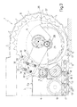
- damping device 26 comprises an auxiliary roller 27, which is smaller in diameter than drive sprocket 8, is fitted to drive sprocket 8 to rotate about an axis 28 parallel to and frontwards of axis 9, and has a peripheral ring 27a of elastic material, preferably rubber, the outer surface of which is coaxial with axis 28 and only presses against surface 16 of shoes 14 along a portion of track 12 located, in use, immediately upstream from the meshing arc and interposed between auxiliary roller 27 and the terrain.
- auxiliary roller 27 is fitted in rotary manner, by means of bearings, to a pin 29 coaxial with axis 28, and is connected rigidly to an L-shaped bracket 30 hinged at one end to drive sprocket 8 to oscillate about axis 9, and hinged at the opposite end, about axis 7, to an end portion of cross member 6.
- Bracket 30 comprises two portions 31 and 32 connected integrally to each other, and of which portion 31 extends upwards from cross member 6 and has, on its free end, two curved slots 33 substantially concentric with axis 9 and engaged by respective pairs of screws 34 fitted to portion 32.
- screws 34 also define, together with slots 33, an adjusting device 35 for adjusting the preload of auxiliary roller 27. That is, adjusting the position of the pairs of screws 34 along respective slots 33 adjusts, by rotating portion 32 about axis 9, the angular position of axis 28 about axis 9 to adjust the preload of auxiliary roller 27 on track 12 between a minimum preload setting ( Figure 2 ) and a maximum preload setting ( Figure 3 ).
- auxiliary roller 27 is adjusted manually by means of a stop screw 36 fitted to portion 31 and pressing on portion 32. That is, after loosening screws 34 to move portion 32 with respect to portion 31, portion 32 can be rotated about axis 9 by simply screwing or unscrewing stop screw 36 to increase or reduce the preload of auxiliary roller 27 respectively.
- bracket 30 as described above may support auxiliary roller 27 non-adjustably, and/or may comprise a single arm connected rigidly to part of frame 6a.
- auxiliary roller 27 is adjusted by known electronic control systems which adjust the position of portion 32, and therefore the angular position of axis 28 about axis 9, automatically as a function of the operating condition of vehicle 2, e.g. the presence of an off-ground load, such as an implement, connected to the rear end of vehicle 2.
- an off-ground load such as an implement
- auxiliary roller 27 maintains a constant distance between axis 9 of drive sprocket 8 and the terrain as track 12 advances, and, whenever a tooth engages the gap between pins 18 of two adjacent links 13, prevents drive sprocket 8 from slumping onto links 13 of track 12 and so generating noise and vibration.
- damping device 26 in addition to a rear portion defined by auxiliary roller 27, also comprises a front portion 26a in turn comprising a pair of front rollers 37 located on opposite sides of idler wheel 10 and which, as explained in detail below, serve to support the portion of track 12 about to wind about idler wheel 10.
- Front rollers 37 are smaller in diameter than idler wheel 10, are fitted to fork 22 to rotate, with respect to fork 22, about an axis 38 parallel to, above, and to the front of axis 11, and have respective rubber-coated peripheral surfaces 39 that press against surface 16 of links 13 to support track 12 along an initial portion of the winding arc of track 12 about idler wheel 10.
- front rollers 37 greatly reduces noise and vibration caused, as is known, by track 12 winding about idler wheel 10, and by links 13 banging against the metal surface of idler wheel 10. This occurs, in particular, along the initial portion of the winding arc of track 12 about idler wheel 10, on account of the severe angular acceleration of links 13 as they are rotated about axis 11, and also on account of the sharp upward movement to which track 12 is very often subjected along the initial portion of the winding arc. That is, on reaching idler wheel 10, track 12, as opposed to being perfectly tangent to idler wheel 10, is held down by its own weight and, at times, by insufficient tension.
- front rollers 37 support the portion of track 12 reaching idler wheel 10, impact of links 13 against idler wheel 10 occurs on the rubber surface of front rollers 37, as opposed to the metal surface of idler wheel 10, thus damping noise and vibration.
- Front rollers 37 also provide for supporting and guiding track 12, and so aligning it perfectly with idler wheel 10, regardless of the tension of track 12 and, hence, the shape of the top branch of track 12 upstream from idler wheel 10.
- each of front rollers 37 (only the outer front roller 37 is shown in Figure 5 ) is fitted adjustably to fork 22 by means of a respective bracket 40 comprising a bottom portion 41 fitted integrally to fork 22 by two screws 42 engaging respective longitudinal slots 43 in bottom portion 41; and a top portion 44, which is fitted integrally to bottom portion 41 by four screws 45 engaging respective slots 46 crosswise to slots 43, and supports relative front roller 37 in rotary manner by means of a pin 47 coaxial with axis 38.
- bottom portion 41 Besides connecting bottom portion 41 to fork 22, screws 42 and slots 43 of each bracket 40 define an adjusting device 48 for adjusting the longitudinal position of relative front roller 37. That is, by loosening screws 42 to slide them along respective slots 43, bottom portion 41 is movable longitudinally with respect to fork 22 by screwing or unscrewing a stop screw 49, fitted to bottom portion 41 and pressing against fork 22, to move front roller 37 frontwards or rearwards and so increase or reduce the preload of front roller 37 respectively.
- each bracket 40 Besides connecting bottom portion 41 to top portion 44, screws 45 and slots 46 of each bracket 40 form part of an adjusting device 50 for adjusting the height of relative front roller 37. That is, by loosening screws 45 to slide them along respective slots 46, top portion 44 is movable vertically with respect to bottom portion 41 by screwing or unscrewing a stop screw 51, fitted to bottom portion 41 and pressing against top portion 44, to move front roller 37 upwards or downwards and so increase or reduce the preload of front roller 37 respectively.
- bracket 40 has a slot 52 at axis 11 to permit easy access by the user to a connection for a greasing device by which to grease the pin of idler wheel 10.
- Slot 52 may either be formed in both brackets 40 or only in the bracket 40 of outer front roller 37.
- each front roller 37 with respect to idler wheel 10 is selected bearing in mind opposite requirements: the diameter of front roller 37, on the one hand, must be small enough for track 12 to wind correctly about idler wheel 10, and, on the other, must be large enough to achieve sufficient contact between its peripheral surface 39 and surface 16 of shoes 14 to effectively dampen vibration and guide track 12.
- each front roller 37 being adjustable independently of the other front roller 37, the two front rollers 37 may be set to respective, even slightly offset, longitudinal positions to increase the overall roller-track contact area and advantageously improve support and guidance of track 12 by front rollers 37 as a whole.
- front rollers 37 are of different diameters. More specifically, in the example shown, the outer front roller 37a is larger in diameter than the inner front roller 37b. In this case, obviously, the two front rollers 37, as opposed to rotating about the same axis, rotate about respective parallel axes 38a and 38b. Moreover, for reasons of size, bracket 40 for supporting and adjusting front roller 37a is located between idler wheel 10 and front roller 37a.
- Figures 8 to 10 show a further variation 26b of the front portion of damping device 26, in which front rollers 37 press against surface 16 of shoes 14 along the whole winding arc, and together replace idler wheel 10.
- front rollers 37 of front portion 26b are fitted to a pin 53 to rotate about an axis 54 (coincident with axis 11 of idler wheel 10 of front portion 26a) parallel to axis 9 and movable longitudinally to adjust the tension of track 12 by means of front rollers 37 and tensioning device 23.
- pin 53 is fitted in rotary manner, with the interposition of bearings, to a support 55 which is integral with the free end of fork 22 and is slid by fork 22 along a bracket 56 integral with carriage 3.
- each front roller 37 comprises a spoked hub 60 fitted with a peripheral ring comprising an outer layer 61 of elastic material, preferably cured rubber, the peripheral surface 62 of which is in constant contact with surface 16 of shoes 14 along the whole winding arc.
- each hub 60 On the side facing the other hub 60, each hub 60 has a conical annular surface 63 which cooperates with a tapered lateral surface 64 of links 13 to align and guide track 12 along the whole winding arc about front rollers 37. Operation of damping device 26 will be clear from the above description, with no further explanation required.
Landscapes
- Engineering & Computer Science (AREA)
- Chemical & Material Sciences (AREA)
- Combustion & Propulsion (AREA)
- Transportation (AREA)
- Mechanical Engineering (AREA)
- Devices For Conveying Motion By Means Of Endless Flexible Members (AREA)
- Harvester Elements (AREA)
- Medicines That Contain Protein Lipid Enzymes And Other Medicines (AREA)
- Radiation-Therapy Devices (AREA)
- Pharmaceuticals Containing Other Organic And Inorganic Compounds (AREA)
- Jib Cranes (AREA)
- Manufacture Of Iron (AREA)
- Friction Gearing (AREA)
Applications Claiming Priority (1)
| Application Number | Priority Date | Filing Date | Title |
|---|---|---|---|
| IT000364A ITTO20070364A1 (it) | 2007-05-23 | 2007-05-23 | Dispositivo di trazione a cingolo |
Publications (2)
| Publication Number | Publication Date |
|---|---|
| EP1995160A1 true EP1995160A1 (de) | 2008-11-26 |
| EP1995160B1 EP1995160B1 (de) | 2010-07-14 |
Family
ID=39432502
Family Applications (2)
| Application Number | Title | Priority Date | Filing Date |
|---|---|---|---|
| EP08154535A Active EP1995160B1 (de) | 2007-05-23 | 2008-04-15 | Raupenzugvorrichtung |
| EP08154672A Active EP1995161B1 (de) | 2007-05-23 | 2008-04-17 | Raupenzugvorrichtung |
Family Applications After (1)
| Application Number | Title | Priority Date | Filing Date |
|---|---|---|---|
| EP08154672A Active EP1995161B1 (de) | 2007-05-23 | 2008-04-17 | Raupenzugvorrichtung |
Country Status (5)
| Country | Link |
|---|---|
| US (2) | US7997666B2 (de) |
| EP (2) | EP1995160B1 (de) |
| AT (2) | ATE473906T1 (de) |
| DE (2) | DE602008001750D1 (de) |
| IT (1) | ITTO20070364A1 (de) |
Families Citing this family (14)
| Publication number | Priority date | Publication date | Assignee | Title |
|---|---|---|---|---|
| US8430188B2 (en) | 2006-12-11 | 2013-04-30 | Vermeer Manufacturing Company | Apparatus for converting a wheeled vehicle to a tracked vehicle |
| WO2008073990A2 (en) | 2006-12-12 | 2008-06-19 | Loegering Mfg. Inc. | Conversion system for a wheeled vehicle |
| ITTO20070364A1 (it) * | 2007-05-23 | 2008-11-24 | Cnh Italia Spa | Dispositivo di trazione a cingolo |
| US8240783B2 (en) * | 2008-08-01 | 2012-08-14 | The Charles Machine Works, Inc. | Track tensioning system |
| US8360535B2 (en) * | 2008-12-02 | 2013-01-29 | Caterpillar Inc. | Sound reducing segmented idler for track-type vehicles |
| US8245800B2 (en) | 2008-12-09 | 2012-08-21 | Vermeer Manufacturing Company | Apparatus for converting a wheeled vehicle to a tracked vehicle |
| US8590987B2 (en) * | 2008-12-18 | 2013-11-26 | Caterpillar Inc. | Idler and undercarriage assembly for track-type machine |
| CA2846662C (en) | 2011-08-31 | 2018-05-22 | Snowgrolic S.A R.L. | Tracked vehicle |
| US9457854B2 (en) | 2014-04-02 | 2016-10-04 | Unverferth Manufacturing Co., Inc. | Track assembly for farm implement |
| EP3356211B1 (de) | 2015-09-29 | 2021-03-10 | ContiTech Transportbandsysteme GmbH | Selbstausrichtender leitradentwurf für gummiraupenkette |
| CN105947003B (zh) * | 2016-01-25 | 2019-04-02 | 青岛克路德机器人有限公司 | 涨紧装置和履带式机器人 |
| US11731715B2 (en) | 2018-02-15 | 2023-08-22 | Soucy International Inc. | Track assembly and vehicle |
| US12185649B2 (en) | 2020-01-21 | 2025-01-07 | David Haynes | Compact, extensible, track laying, agricultural tractor |
| CN113525540B (zh) * | 2020-04-15 | 2022-06-28 | 黑龙江重兴机械设备有限公司 | 四排减震轮组的半履带行走装置 |
Citations (2)
| Publication number | Priority date | Publication date | Assignee | Title |
|---|---|---|---|---|
| EP0810149A2 (de) * | 1996-05-28 | 1997-12-03 | Hitachi Construction Machinery Co., Ltd. | Antriebsvorrichtung für ein Raupenrad von einem Gleiskettenfahrzeug |
| EP1666345A2 (de) * | 2004-12-01 | 2006-06-07 | Komatsu Ltd | Raupenfahrzeug |
Family Cites Families (16)
| Publication number | Priority date | Publication date | Assignee | Title |
|---|---|---|---|---|
| US2049858A (en) * | 1930-10-06 | 1936-08-04 | Allis Chalmers Mfg Co | Tractor frame suspension |
| US2984524A (en) * | 1957-04-15 | 1961-05-16 | Kelsey Hayes Co | Road wheel with vulcanized wear ring |
| US3733107A (en) * | 1971-07-19 | 1973-05-15 | Bombardier Ltd | Endless track tension release mechanism |
| US3901563A (en) * | 1974-05-17 | 1975-08-26 | Caterpillar Tractor Co | Hydromechanical recoil and track adjuster system |
| US4059314A (en) * | 1976-02-27 | 1977-11-22 | Jacob Amstutz | Track assembly for tracked vehicles |
| US4082371A (en) * | 1976-08-02 | 1978-04-04 | Deere & Company | Support and guide for a track of a track-laying vehicle |
| US4083610A (en) * | 1977-04-01 | 1978-04-11 | John Kruchowski | Bearing assembly utilizing a tapered bushing holder |
| US4506934A (en) * | 1983-01-07 | 1985-03-26 | Fmc Corporation | Chordal action isolation wheel assembly |
| US4887872A (en) * | 1989-01-17 | 1989-12-19 | Caterpillar Inc. | Track adjuster flow control mechanism |
| US5409305A (en) * | 1992-08-17 | 1995-04-25 | Deere & Company | Undercarriage for a track laying vehicle |
| US5312176A (en) * | 1992-09-25 | 1994-05-17 | Catepillar Inc. | Self-aligning idler wheel assembly |
| DE4330833A1 (de) * | 1993-07-16 | 1995-03-23 | Intertractor Ag | Vorrichtung zum Spannen und Abfedern des Leitrades von Kettenfahrzeugen |
| ATE238191T1 (de) * | 1995-10-13 | 2003-05-15 | Intertractor Gmbh | Vorrichtung zum spannen und abfedern des leitrades von kettenfahrzeugen |
| US6267459B1 (en) * | 1999-12-13 | 2001-07-31 | Caterpillar Inc. | Automatic belt alignment system for an endless track laying work machine |
| US6869153B2 (en) * | 2002-04-09 | 2005-03-22 | Deere & Company | Track and track assembly for a track laying vehicle |
| ITTO20070364A1 (it) * | 2007-05-23 | 2008-11-24 | Cnh Italia Spa | Dispositivo di trazione a cingolo |
-
2007
- 2007-05-23 IT IT000364A patent/ITTO20070364A1/it unknown
-
2008
- 2008-04-15 DE DE602008001750T patent/DE602008001750D1/de active Active
- 2008-04-15 EP EP08154535A patent/EP1995160B1/de active Active
- 2008-04-15 AT AT08154535T patent/ATE473906T1/de not_active IP Right Cessation
- 2008-04-17 EP EP08154672A patent/EP1995161B1/de active Active
- 2008-04-17 DE DE602008001683T patent/DE602008001683D1/de active Active
- 2008-04-17 AT AT08154672T patent/ATE473149T1/de not_active IP Right Cessation
- 2008-05-23 US US12/126,282 patent/US7997666B2/en active Active
-
2011
- 2011-06-22 US US13/166,625 patent/US20110248562A1/en not_active Abandoned
Patent Citations (3)
| Publication number | Priority date | Publication date | Assignee | Title |
|---|---|---|---|---|
| EP0810149A2 (de) * | 1996-05-28 | 1997-12-03 | Hitachi Construction Machinery Co., Ltd. | Antriebsvorrichtung für ein Raupenrad von einem Gleiskettenfahrzeug |
| EP0810149B1 (de) | 1996-05-28 | 2002-05-08 | Hitachi Construction Machinery Co., Ltd. | Antriebsvorrichtung für eine Raupenkette von Raupenfahrzeugen |
| EP1666345A2 (de) * | 2004-12-01 | 2006-06-07 | Komatsu Ltd | Raupenfahrzeug |
Also Published As
| Publication number | Publication date |
|---|---|
| US20090021073A1 (en) | 2009-01-22 |
| DE602008001683D1 (de) | 2010-08-19 |
| ITTO20070364A1 (it) | 2008-11-24 |
| EP1995160B1 (de) | 2010-07-14 |
| EP1995161A1 (de) | 2008-11-26 |
| ATE473149T1 (de) | 2010-07-15 |
| US7997666B2 (en) | 2011-08-16 |
| US20110248562A1 (en) | 2011-10-13 |
| ATE473906T1 (de) | 2010-07-15 |
| EP1995161B1 (de) | 2010-07-07 |
| DE602008001750D1 (de) | 2010-08-26 |
Similar Documents
| Publication | Publication Date | Title |
|---|---|---|
| EP1995160B1 (de) | Raupenzugvorrichtung | |
| CA2491581A1 (en) | Track assembly | |
| US10493345B2 (en) | Bike trainer guide apparatus | |
| US7455141B2 (en) | Track drive system | |
| DE20114331U1 (de) | Lauf-Tretroller | |
| US7083241B2 (en) | Track tensioner for a wheel-driven skid steer | |
| JP2010000838A (ja) | クローラ走行装置 | |
| EP0808766B1 (de) | Raupenantriebsvorrichtung | |
| CN210084241U (zh) | 一种便于调节张紧装置的输送带 | |
| CN214286676U (zh) | 一种游乐设备摆动滑轮装置 | |
| EP1407986A1 (de) | Treib/Spannvorrichtung für Transportband und Transportvorrichtung mit einer solchen Vorrichtung | |
| CN215553643U (zh) | 一种支重轮履带式行走装置 | |
| CN217994621U (zh) | 一种快速行走的履带式农机底盘 | |
| US3717211A (en) | Spring mounting for snowmobile bogie wheels | |
| CN201953928U (zh) | 链条或皮带张紧装置 | |
| CN216343733U (zh) | 一种传动张紧装置 | |
| CN210175751U (zh) | 皮带机皮带防跑偏机构及其皮带机 | |
| CN220765536U (zh) | 三角带输送装置 | |
| CN217200288U (zh) | 一种板链式输送带专用张紧器 | |
| CN217574165U (zh) | 辊压式物料松散装置 | |
| CN109018917B (zh) | 一种传输带断裂急停装置 | |
| KR20090073922A (ko) | 충격완화 삼각텐션로울러 | |
| CN219945191U (zh) | 一种电梯对重轮横向压装组件 | |
| CN105855975B (zh) | 一种可方便调整间隙的机械加工设备 | |
| CN210258615U (zh) | 履带行走机构 |
Legal Events
| Date | Code | Title | Description |
|---|---|---|---|
| PUAI | Public reference made under article 153(3) epc to a published international application that has entered the european phase |
Free format text: ORIGINAL CODE: 0009012 |
|
| AK | Designated contracting states |
Kind code of ref document: A1 Designated state(s): AT BE BG CH CY CZ DE DK EE ES FI FR GB GR HR HU IE IS IT LI LT LU LV MC MT NL NO PL PT RO SE SI SK TR |
|
| AX | Request for extension of the european patent |
Extension state: AL BA MK RS |
|
| 17P | Request for examination filed |
Effective date: 20090526 |
|
| 17Q | First examination report despatched |
Effective date: 20090619 |
|
| AKX | Designation fees paid |
Designated state(s): AT BE BG CH CY CZ DE DK EE ES FI FR GB GR HR HU IE IS IT LI LT LU LV MC MT NL NO PL PT RO SE SI SK TR |
|
| GRAP | Despatch of communication of intention to grant a patent |
Free format text: ORIGINAL CODE: EPIDOSNIGR1 |
|
| GRAS | Grant fee paid |
Free format text: ORIGINAL CODE: EPIDOSNIGR3 |
|
| GRAA | (expected) grant |
Free format text: ORIGINAL CODE: 0009210 |
|
| AK | Designated contracting states |
Kind code of ref document: B1 Designated state(s): AT BE BG CH CY CZ DE DK EE ES FI FR GB GR HR HU IE IS IT LI LT LU LV MC MT NL NO PL PT RO SE SI SK TR |
|
| REG | Reference to a national code |
Ref country code: GB Ref legal event code: FG4D |
|
| REG | Reference to a national code |
Ref country code: CH Ref legal event code: EP |
|
| REG | Reference to a national code |
Ref country code: IE Ref legal event code: FG4D |
|
| REF | Corresponds to: |
Ref document number: 602008001750 Country of ref document: DE Date of ref document: 20100826 Kind code of ref document: P |
|
| REG | Reference to a national code |
Ref country code: NL Ref legal event code: VDEP Effective date: 20100714 |
|
| LTIE | Lt: invalidation of european patent or patent extension |
Effective date: 20100714 |
|
| PG25 | Lapsed in a contracting state [announced via postgrant information from national office to epo] |
Ref country code: LT Free format text: LAPSE BECAUSE OF FAILURE TO SUBMIT A TRANSLATION OF THE DESCRIPTION OR TO PAY THE FEE WITHIN THE PRESCRIBED TIME-LIMIT Effective date: 20100714 Ref country code: NL Free format text: LAPSE BECAUSE OF FAILURE TO SUBMIT A TRANSLATION OF THE DESCRIPTION OR TO PAY THE FEE WITHIN THE PRESCRIBED TIME-LIMIT Effective date: 20100714 Ref country code: NO Free format text: LAPSE BECAUSE OF FAILURE TO SUBMIT A TRANSLATION OF THE DESCRIPTION OR TO PAY THE FEE WITHIN THE PRESCRIBED TIME-LIMIT Effective date: 20101014 Ref country code: AT Free format text: LAPSE BECAUSE OF FAILURE TO SUBMIT A TRANSLATION OF THE DESCRIPTION OR TO PAY THE FEE WITHIN THE PRESCRIBED TIME-LIMIT Effective date: 20100714 Ref country code: FI Free format text: LAPSE BECAUSE OF FAILURE TO SUBMIT A TRANSLATION OF THE DESCRIPTION OR TO PAY THE FEE WITHIN THE PRESCRIBED TIME-LIMIT Effective date: 20100714 |
|
| PG25 | Lapsed in a contracting state [announced via postgrant information from national office to epo] |
Ref country code: PL Free format text: LAPSE BECAUSE OF FAILURE TO SUBMIT A TRANSLATION OF THE DESCRIPTION OR TO PAY THE FEE WITHIN THE PRESCRIBED TIME-LIMIT Effective date: 20100714 Ref country code: SI Free format text: LAPSE BECAUSE OF FAILURE TO SUBMIT A TRANSLATION OF THE DESCRIPTION OR TO PAY THE FEE WITHIN THE PRESCRIBED TIME-LIMIT Effective date: 20100714 Ref country code: BG Free format text: LAPSE BECAUSE OF FAILURE TO SUBMIT A TRANSLATION OF THE DESCRIPTION OR TO PAY THE FEE WITHIN THE PRESCRIBED TIME-LIMIT Effective date: 20101014 Ref country code: CY Free format text: LAPSE BECAUSE OF FAILURE TO SUBMIT A TRANSLATION OF THE DESCRIPTION OR TO PAY THE FEE WITHIN THE PRESCRIBED TIME-LIMIT Effective date: 20100714 Ref country code: HR Free format text: LAPSE BECAUSE OF FAILURE TO SUBMIT A TRANSLATION OF THE DESCRIPTION OR TO PAY THE FEE WITHIN THE PRESCRIBED TIME-LIMIT Effective date: 20100714 Ref country code: IS Free format text: LAPSE BECAUSE OF FAILURE TO SUBMIT A TRANSLATION OF THE DESCRIPTION OR TO PAY THE FEE WITHIN THE PRESCRIBED TIME-LIMIT Effective date: 20101114 |
|
| PG25 | Lapsed in a contracting state [announced via postgrant information from national office to epo] |
Ref country code: BE Free format text: LAPSE BECAUSE OF FAILURE TO SUBMIT A TRANSLATION OF THE DESCRIPTION OR TO PAY THE FEE WITHIN THE PRESCRIBED TIME-LIMIT Effective date: 20100714 Ref country code: GR Free format text: LAPSE BECAUSE OF FAILURE TO SUBMIT A TRANSLATION OF THE DESCRIPTION OR TO PAY THE FEE WITHIN THE PRESCRIBED TIME-LIMIT Effective date: 20101015 Ref country code: LV Free format text: LAPSE BECAUSE OF FAILURE TO SUBMIT A TRANSLATION OF THE DESCRIPTION OR TO PAY THE FEE WITHIN THE PRESCRIBED TIME-LIMIT Effective date: 20100714 Ref country code: SE Free format text: LAPSE BECAUSE OF FAILURE TO SUBMIT A TRANSLATION OF THE DESCRIPTION OR TO PAY THE FEE WITHIN THE PRESCRIBED TIME-LIMIT Effective date: 20100714 |
|
| PG25 | Lapsed in a contracting state [announced via postgrant information from national office to epo] |
Ref country code: DK Free format text: LAPSE BECAUSE OF FAILURE TO SUBMIT A TRANSLATION OF THE DESCRIPTION OR TO PAY THE FEE WITHIN THE PRESCRIBED TIME-LIMIT Effective date: 20100714 |
|
| PLBE | No opposition filed within time limit |
Free format text: ORIGINAL CODE: 0009261 |
|
| STAA | Information on the status of an ep patent application or granted ep patent |
Free format text: STATUS: NO OPPOSITION FILED WITHIN TIME LIMIT |
|
| PG25 | Lapsed in a contracting state [announced via postgrant information from national office to epo] |
Ref country code: RO Free format text: LAPSE BECAUSE OF FAILURE TO SUBMIT A TRANSLATION OF THE DESCRIPTION OR TO PAY THE FEE WITHIN THE PRESCRIBED TIME-LIMIT Effective date: 20100714 Ref country code: EE Free format text: LAPSE BECAUSE OF FAILURE TO SUBMIT A TRANSLATION OF THE DESCRIPTION OR TO PAY THE FEE WITHIN THE PRESCRIBED TIME-LIMIT Effective date: 20100714 Ref country code: CZ Free format text: LAPSE BECAUSE OF FAILURE TO SUBMIT A TRANSLATION OF THE DESCRIPTION OR TO PAY THE FEE WITHIN THE PRESCRIBED TIME-LIMIT Effective date: 20100714 Ref country code: SK Free format text: LAPSE BECAUSE OF FAILURE TO SUBMIT A TRANSLATION OF THE DESCRIPTION OR TO PAY THE FEE WITHIN THE PRESCRIBED TIME-LIMIT Effective date: 20100714 |
|
| 26N | No opposition filed |
Effective date: 20110415 |
|
| PG25 | Lapsed in a contracting state [announced via postgrant information from national office to epo] |
Ref country code: ES Free format text: LAPSE BECAUSE OF FAILURE TO SUBMIT A TRANSLATION OF THE DESCRIPTION OR TO PAY THE FEE WITHIN THE PRESCRIBED TIME-LIMIT Effective date: 20101025 |
|
| REG | Reference to a national code |
Ref country code: DE Ref legal event code: R097 Ref document number: 602008001750 Country of ref document: DE Effective date: 20110415 |
|
| PG25 | Lapsed in a contracting state [announced via postgrant information from national office to epo] |
Ref country code: MC Free format text: LAPSE BECAUSE OF NON-PAYMENT OF DUE FEES Effective date: 20110430 |
|
| PG25 | Lapsed in a contracting state [announced via postgrant information from national office to epo] |
Ref country code: MT Free format text: LAPSE BECAUSE OF FAILURE TO SUBMIT A TRANSLATION OF THE DESCRIPTION OR TO PAY THE FEE WITHIN THE PRESCRIBED TIME-LIMIT Effective date: 20100714 |
|
| REG | Reference to a national code |
Ref country code: IE Ref legal event code: MM4A |
|
| PG25 | Lapsed in a contracting state [announced via postgrant information from national office to epo] |
Ref country code: IE Free format text: LAPSE BECAUSE OF NON-PAYMENT OF DUE FEES Effective date: 20110415 |
|
| REG | Reference to a national code |
Ref country code: CH Ref legal event code: PL |
|
| PG25 | Lapsed in a contracting state [announced via postgrant information from national office to epo] |
Ref country code: CH Free format text: LAPSE BECAUSE OF NON-PAYMENT OF DUE FEES Effective date: 20120430 Ref country code: LI Free format text: LAPSE BECAUSE OF NON-PAYMENT OF DUE FEES Effective date: 20120430 |
|
| PG25 | Lapsed in a contracting state [announced via postgrant information from national office to epo] |
Ref country code: LU Free format text: LAPSE BECAUSE OF NON-PAYMENT OF DUE FEES Effective date: 20110415 |
|
| PG25 | Lapsed in a contracting state [announced via postgrant information from national office to epo] |
Ref country code: PT Free format text: LAPSE BECAUSE OF NON-PAYMENT OF DUE FEES Effective date: 20100714 |
|
| PG25 | Lapsed in a contracting state [announced via postgrant information from national office to epo] |
Ref country code: TR Free format text: LAPSE BECAUSE OF FAILURE TO SUBMIT A TRANSLATION OF THE DESCRIPTION OR TO PAY THE FEE WITHIN THE PRESCRIBED TIME-LIMIT Effective date: 20100714 |
|
| PG25 | Lapsed in a contracting state [announced via postgrant information from national office to epo] |
Ref country code: HU Free format text: LAPSE BECAUSE OF FAILURE TO SUBMIT A TRANSLATION OF THE DESCRIPTION OR TO PAY THE FEE WITHIN THE PRESCRIBED TIME-LIMIT Effective date: 20100714 |
|
| REG | Reference to a national code |
Ref country code: DE Ref legal event code: R082 Ref document number: 602008001750 Country of ref document: DE Representative=s name: PATENTANWAELTE WALLACH, KOCH & PARTNER, DE |
|
| REG | Reference to a national code |
Ref country code: DE Ref legal event code: R082 Ref document number: 602008001750 Country of ref document: DE Representative=s name: PATENTANWAELTE WALLACH, KOCH & PARTNER, DE Effective date: 20140623 Ref country code: DE Ref legal event code: R081 Ref document number: 602008001750 Country of ref document: DE Owner name: CNH INDUSTRIAL ITALIA S.P.A., IT Free format text: FORMER OWNER: CNH ITALIA S.P.A., MODENA, IT Effective date: 20140623 Ref country code: DE Ref legal event code: R082 Ref document number: 602008001750 Country of ref document: DE Representative=s name: PATENTANWAELTE WALLACH, KOCH, DR. HAIBACH, FEL, DE Effective date: 20140623 |
|
| REG | Reference to a national code |
Ref country code: FR Ref legal event code: CD Owner name: CNH INDUSTRIAL ITALIA S.P.A. Effective date: 20150313 |
|
| REG | Reference to a national code |
Ref country code: FR Ref legal event code: PLFP Year of fee payment: 9 |
|
| REG | Reference to a national code |
Ref country code: FR Ref legal event code: PLFP Year of fee payment: 10 |
|
| REG | Reference to a national code |
Ref country code: FR Ref legal event code: PLFP Year of fee payment: 11 |
|
| REG | Reference to a national code |
Ref country code: DE Ref legal event code: R082 Ref document number: 602008001750 Country of ref document: DE Representative=s name: MEISSNER BOLTE PATENTANWAELTE RECHTSANWAELTE P, DE |
|
| PGFP | Annual fee paid to national office [announced via postgrant information from national office to epo] |
Ref country code: DE Payment date: 20200429 Year of fee payment: 13 Ref country code: FR Payment date: 20200420 Year of fee payment: 13 |
|
| PGFP | Annual fee paid to national office [announced via postgrant information from national office to epo] |
Ref country code: GB Payment date: 20200424 Year of fee payment: 13 |
|
| REG | Reference to a national code |
Ref country code: DE Ref legal event code: R119 Ref document number: 602008001750 Country of ref document: DE |
|
| GBPC | Gb: european patent ceased through non-payment of renewal fee |
Effective date: 20210415 |
|
| PG25 | Lapsed in a contracting state [announced via postgrant information from national office to epo] |
Ref country code: GB Free format text: LAPSE BECAUSE OF NON-PAYMENT OF DUE FEES Effective date: 20210415 Ref country code: FR Free format text: LAPSE BECAUSE OF NON-PAYMENT OF DUE FEES Effective date: 20210430 Ref country code: DE Free format text: LAPSE BECAUSE OF NON-PAYMENT OF DUE FEES Effective date: 20211103 |
|
| PGFP | Annual fee paid to national office [announced via postgrant information from national office to epo] |
Ref country code: IT Payment date: 20250422 Year of fee payment: 18 |