EP1995168A1 - Corps flottant et ponton le composant - Google Patents
Corps flottant et ponton le composant Download PDFInfo
- Publication number
- EP1995168A1 EP1995168A1 EP08009578A EP08009578A EP1995168A1 EP 1995168 A1 EP1995168 A1 EP 1995168A1 EP 08009578 A EP08009578 A EP 08009578A EP 08009578 A EP08009578 A EP 08009578A EP 1995168 A1 EP1995168 A1 EP 1995168A1
- Authority
- EP
- European Patent Office
- Prior art keywords
- devices
- pontoon
- floating body
- propulsion devices
- propulsion
- Prior art date
- Legal status (The legal status is an assumption and is not a legal conclusion. Google has not performed a legal analysis and makes no representation as to the accuracy of the status listed.)
- Withdrawn
Links
- XLYOFNOQVPJJNP-UHFFFAOYSA-N water Substances O XLYOFNOQVPJJNP-UHFFFAOYSA-N 0.000 claims abstract description 14
- 238000013461 design Methods 0.000 claims abstract description 11
- 239000002131 composite material Substances 0.000 claims description 59
- 238000001514 detection method Methods 0.000 claims description 6
- 238000002485 combustion reaction Methods 0.000 claims description 5
- 230000000694 effects Effects 0.000 claims description 4
- 239000000446 fuel Substances 0.000 claims description 4
- 230000008878 coupling Effects 0.000 claims description 3
- 238000010168 coupling process Methods 0.000 claims description 3
- 238000005859 coupling reaction Methods 0.000 claims description 3
- 230000008901 benefit Effects 0.000 description 11
- 238000010276 construction Methods 0.000 description 9
- 230000005540 biological transmission Effects 0.000 description 6
- 241000380131 Ammophila arenaria Species 0.000 description 3
- 239000000463 material Substances 0.000 description 3
- 238000012423 maintenance Methods 0.000 description 2
- 238000000034 method Methods 0.000 description 2
- 230000008569 process Effects 0.000 description 2
- 230000006641 stabilisation Effects 0.000 description 2
- 238000011105 stabilization Methods 0.000 description 2
- 229910000831 Steel Inorganic materials 0.000 description 1
- 230000004308 accommodation Effects 0.000 description 1
- 230000009471 action Effects 0.000 description 1
- 230000009286 beneficial effect Effects 0.000 description 1
- 230000001419 dependent effect Effects 0.000 description 1
- 238000011161 development Methods 0.000 description 1
- 238000010348 incorporation Methods 0.000 description 1
- 239000002184 metal Substances 0.000 description 1
- 239000000203 mixture Substances 0.000 description 1
- 238000012986 modification Methods 0.000 description 1
- 230000004048 modification Effects 0.000 description 1
- 230000009467 reduction Effects 0.000 description 1
- 230000008054 signal transmission Effects 0.000 description 1
- 239000010959 steel Substances 0.000 description 1
- 238000006467 substitution reaction Methods 0.000 description 1
- 230000009182 swimming Effects 0.000 description 1
- 230000007704 transition Effects 0.000 description 1
- 238000013519 translation Methods 0.000 description 1
- 239000003643 water by type Substances 0.000 description 1
- 239000002023 wood Substances 0.000 description 1
Images


Classifications
-
- B—PERFORMING OPERATIONS; TRANSPORTING
- B63—SHIPS OR OTHER WATERBORNE VESSELS; RELATED EQUIPMENT
- B63B—SHIPS OR OTHER WATERBORNE VESSELS; EQUIPMENT FOR SHIPPING
- B63B35/00—Vessels or similar floating structures specially adapted for specific purposes and not otherwise provided for
- B63B35/34—Pontoons
- B63B35/38—Rigidly-interconnected pontoons
-
- E—FIXED CONSTRUCTIONS
- E01—CONSTRUCTION OF ROADS, RAILWAYS, OR BRIDGES
- E01D—CONSTRUCTION OF BRIDGES, ELEVATED ROADWAYS OR VIADUCTS; ASSEMBLY OF BRIDGES
- E01D15/00—Movable or portable bridges; Floating bridges
- E01D15/14—Floating bridges, e.g. pontoon bridges
Definitions
- the present invention relates to a floating body according to the preamble of claim 1 and a pontoon thereof.
- the floating body may itself consist of a single floating element or a plurality of pre-connected floating elements, such as joints of pre-connected floating elements, to allow for space-saving transport.
- a floating body in the context of the present invention are not boats in the traditional sense to understand, but it is platforms, by means of which, for example, work equipment can be positioned on the water, but not designed for transporting such work equipment on the water and used become.
- the present invention has and achieves the goal of creating a maneuverable float as well as possible. Furthermore, the present invention has and aims to provide a simple, fast and accurate to build pontoon with at least one float or a floating body composite.
- a floating body with at least one floating element and associated with this propulsion devices created that contain at least one 360 ° or all around controllable drive.
- the propulsion devices contain two 360 ° or completely controllable drives. It is likewise preferred if at least one controllable drive is a controllable pump jet and / or if each controllable drive and in particular pump jet has a flat-water design.
- the term "pump jet” is generally referred to herein as pump jet propulsion and is further generalized to a propulsion propulsion device, each as noted above, preferably in a particularly flat design or construction.
- electrical drive means are provided for one or more drives or pump jets, and / or that a stepless speed control is included, wherein in particular the stepless speed control is fed via an inverter.
- a further preferred embodiment consists in that energy connection devices for connecting the propulsion devices by means of energy-connecting devices to external power supply devices are arranged on the floating body or the propulsion devices connected thereto.
- energy supply devices are provided which contain at least one energy supply unit, which represents a separate structural unit with respect to the floating body, and are associated with energy connection devices for connecting the propulsion devices by means of energy connection devices to the at least one energy supply unit the floating body or the propulsion devices connected thereto are.
- Such a power supply unit preferably contains at least one generator set, which itself in turn contains in particular an internal combustion engine and / or a gas turbine as well as a generator; alternatively or additionally, the generator set may include a fuel cell.
- the power supply unit in particular the generator set, may also be provided with preference that it or it is at least temporarily disposable with respect to the floating body and on the at least one float, wherein the power supply unit, in particular the generator set, preferably for a shunting or ferry operation of the float on the at least one floating element is at least temporarily arranged.
- energy-connecting devices include pluggable cable connections, which are designed for simultaneous fixing of the float to another floating body.
- a dinghy coupled with a bridge constructed from the floating bodies or safety boat of the bridge simultaneously serves as an energy supplier and provides the external energy supply facilities.
- a control for the propulsion devices is provided.
- the controller contain input receiving devices for wireless input devices or control connection devices for wired input devices that can be connected to the controller via control connection devices, wherein furthermore in particular the wireless input transmission devices or the wired input devices are mobile with respect to the at least one floating element and on the at least a floating element at least temporarily can be arranged.
- the invention also provides a pontoon with at least one floating body to achieve said object, as explained in various embodiments above, wherein at least two floating bodies are detachable with each other are connected, of which at least one float has propulsion devices.
- the propulsion devices of at least one floating body contain at least one drive or pump jet with electric drive devices
- external power supply devices for the propulsion devices are provided with propulsion devices with respect to the at least one floating body.
- the external energy supply devices contain at least one energy supply unit for the common energy supply of the propulsion devices of at least two floats, or that are provided for the propulsion devices of at least one float external power supply devices or their at least one power supply unit / is.
- the external energy supply devices or their at least one energy supply unit for the propulsion devices of at least two floats are central and / or land based, or that the external energy supply devices or their at least one energy supply unit for a shunting or ferry operation of at least two interconnected floating bodies on a float at least temporarily can be arranged / is. It can also be provided with preference that energy-connecting means for connecting the external power supply means or their at least one power supply unit are provided and pluggable cable connections, which are designed for simultaneously fixing a floating body to another floating body.
- the wireless input transmission devices or the wired input devices are temporarily arranged or placed on a floater provided with propulsion devices during an operating requirement of the propulsion devices, or that the wireless input transmission devices or the wired input devices are external and in particular during an operating requirement of the propulsion devices centrally and / or land-based with respect to all contained floating bodies are arranged or placed.
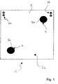
- Fig. 1 is shown schematically in plan view a first embodiment of a pontoon 1 with a float 2a.
- the floating body 2a consists of several vorverbundenen floating elements, such as two or three floating elements, which may be together or possibly hinged on possibly parallel aligned joints, to be easier to transport, as is known in the practice.
- the propulsion devices 4 could also be formed by only one pump jet or contain only one pump jet, in which case direction and / or orientation stabilization devices, such as a keel or a fin or a plurality of them, may advantageously be combined in order to be able to ensure directional propulsion , It is also possible to provide a drive, which can be controlled in particular with respect to the drive power, in terms of alignment with another drive of a different design even with a pump jet which can be controlled by 360 °. In the simplest form, however, a 360 ° controllable pump jet or other suitable drive alone may be sufficient to ensure targeted and directional propulsion.
- the design in concrete is also dependent on the particular application of the pontoon as a bridge, platform, ferry, etc.
- the two pump jets 5a and 5b have a shallow-water configuration which is generally known and therefore need not be further explained or shown here. Furthermore, the two pump jets 5a and 5b each have electrical drive means, as they are also known in practice, so that a closer engagement can be omitted here. The same applies to an infinitely variable speed control of these electric drive devices, in particular via an inverter.
- Energy connection devices 7 are arranged for connecting the propulsion devices 4 by means of energy-connecting devices 8 to external power supply devices 9 on the float 2a.
- the energy-connection devices 7 are integrated in this embodiment in the connectors 6a and 6b to the float 2, wherein only the connectors 6a are used to connect to the power connectors 8 in the form of a power cable 10, the power to the devices. 9 leads, from there to conduct electrical energy or simply electrical power to the propulsion devices 4.
- purely mechanical and purely energy-transmitting connections can be provided physically separated from one another.
- the energy supply unit 11, as in the present case the generator set 12, is mobile with respect to the one floating element 3 and only temporarily set up on the one floating element 3 as long as the propulsion devices 4 are required for driving or maneuvering. Thereafter, the connection means 8 can be released from the power connection means 7, and the power supply unit 11 can be removed from the floating member 3 of the floating body 2a.
- the power supply unit 11 can be easily driven on land. Otherwise, the power supply unit 11 can be reloaded onto another floating body or a boat and brought to land, for example, where it is available, in particular, for supplying energy to further floating bodies. Also, e.g. with a helicopter, the power supply unit 11 can be picked up by the float 2a.
- the mobility of the power supply unit 11 thus leads on the one hand to the advantage that a plurality of floating bodies are not required for a plurality of power supply units, but at minimum a power supply unit is sufficient for a plurality of floats, and also leads to the advantage that the entire surface of the Float 2a or pontoons 1 is available as a usable area and not even a partial area is lost by the power supply unit. All this is achieved in that the power supply unit, in particular the generator set, only temporarily for a shunting or a Fähr congress the present a float 2 a on the floating element 3 is arranged.
- the energy connection devices 8 include a pluggable cable connection with the power cable 10.
- This pluggable connection is integrated in the plug connections 6a and 6b on the floating body 2a, which are designed for simultaneously fixing the floating body 2a to another floating body. as in connection with further embodiments later with reference to FIGS Fig. 3 and 4 is still shown and explained.
- the full space advantage is thereby, as already mentioned, obtained by the fact that the wireless input transmitting devices 16 or the wired input devices with respect to the at least one floating element 3 are mobile and on the at least one floating element 3 only be temporarily arranged, just as long as a ferry or Rangier ses is required.
- FIG. 3 schematically is a plan view of a third embodiment with a pontoon 1 with a total of five floats 2a, 2b, 2c, 2d and 2e shown.
- the floating body 2a is identical to the floating body 2b, 2c, 2d and 2e equipped and temporarily provided with the mobile power supply unit 11 and the freely movable control station 18, wherein the other components and features also according to the details of the embodiment in the Fig. 2 are realized.
- the mobile power supply unit 11 is connected to the propulsion devices 4 of the floating body 2 a via the plug connection 6 a to the floating body 2 a, but also a fixing of the floating body 2 a to the floating body 2 c takes place. This fixation is carried out detachable.
- the floats 2 b, 2 c, 2 d and 2 e contain propulsion devices 4, and these floats 2 b, 2 c, 2 d and 2 e are accordingly equipped like the floating body 2 a according to FIG Fig. 1 .
- the floats 2b, 2c, 2d and 2e are fixed to each other via their connectors 6a and 6b but releasably connected, as the float 2a is connected to the float 2c.
- the propulsion devices 4 of the floating bodies 2b, 2c, 2d and 2e are also connected to the energy supply unit 11 on the floating body 2a via the respective plug connections 6a and 6b.
- the respective individual propulsion devices 4 of the individual floats 2a, 2b, 2c, 2d and 2e themselves each contain a control 15 with input receiving devices 16 for the wireless input transmitting devices 17, which are integrated in the freely movable control station 18.
- the control station 18, like the power supply unit 11, can be removed from the floating element 3 of the floating body 2a. This results in the same advantages as already mentioned above in connection with the mobility of the energy supply unit 11 or generally the power supply devices 9 have been explained.
- the pontoon 1 in operation, the pontoon 1 according to the Fig. 3 by connecting the individual floats 2a, 2b, 2c, 2d and 2e via their connectors 6a and 6b in the in the Fig. 3 shown arrangement of a bank A forth.
- the pontoon 1 can be moved in each of its construction stages on the one hand to the opposite bank B and on the other hand are kept stable against the action of the flow direction of a flow S.
- all controls 15 of the respective propulsion devices 4 of all floats 2a, 2b, 2c, 2d and 2e simultaneously controlled by the control station 18 via its input transmitting devices 17 to the input receiving means 16 of the controllers 15 and control accordingly again to associated propulsion devices 4.
- the Fig. 3 it can be seen that it will be necessary to span the entire route between the bank A and the bank B, to connect two more floats.
- the arrangement of the float 2 a with the mobile power supply unit 11 and the freely movable control station 18 in addition to the row arrangement of the floating body 2 b, 2 c, 2 d and 2 e and here further supplemented floating body has the advantage that immediately after completing the required number of floats to span the entire route between the shore A and the shore B and reaching the final position for this whole of the floating body, the mobile power supply unit 11 and the freely movable control station 18 need not be removed before the pontoon can be used as a bridge otherwise.
- propulsion devices 4 of the floating body 2 a can be dispensed with in the floats 2 b, 2 c, 2 d and 2 e.
- a use of a plurality of floats with propulsion devices has the advantage that on the one hand the individual propulsion devices need not be designed to be large and strong, and on the other hand, the maneuverability of the entire pontoon 1 is greatly improved.
- the floating body 2a can also be spoken by a base element of the floating body composite or pontoon.
- Fig. 4 illustrates that the power supply devices 9 and / or a control station 18 with input transmitting devices 17 or wired input devices connected, if necessary, with appropriate cables can also be positioned and remain on land. That this embodiment is not limited to five floats is symbolized by the fact that the float 2b is shown in dashed lines and stands, so to speak, symbolically for any number of floats.
- a further facilitation in the construction and use of a pontoon of multiple floats is achieved when facilities for particular automatic detection of the number of all involved in the pontoon composite floats with and / or without propulsion devices and the positions and / or arrangements of all on the pontoon composite Floats involved in pontoon composite and for transmitting the detected states of at least the control of the propulsion devices of a floating body and preferably the controls of all the propulsion devices involved are provided.
- the number and arrangement information can, of course, additionally or alternatively go to the input transmitting devices 17 or wired input devices, where they are taken into account in the control of all participating propulsion devices, so that a desired and coordinated movement of the pontoon 1 is possible.
- the control or the controls or the input transmitting devices 17 or wired input devices are designed to suitably drive the respective propulsion devices with and without propulsion devices taking into account the detected and transmitted number, positions and arrangement of the floating bodies involved in the pontoon assembly to effect a desired or required movement of the entire pontoon composite.
- the motor boat 19 has a plug connection 6a, in which, as in the second embodiment according to the Fig. 2 Energy connection means 7 for connecting the propulsion devices 4 of the floats 2a, 2b, 2c, 2d and 2e (which are interconnected by means of the connectors 6a, 6b, in which, for example, energy connection devices 7 are integrated to pass from float to float energy and to be able to provide each float 2 a, 2 b, 2 c, 2 d and 2 e) are integrated by means of energy-connection means 8 to external power supply means 9 on the motor boat 19.
- the power supply devices 9 include a power supply unit 11, which represents a separate unit with respect to the units of the motor boat 19.
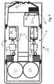
- the motor boat 19 has as a separate unit itself, for example, a pump jet 21 with, for example, a permanent magnet motor for maneuvering and controlling and for the drive, as exemplified in the Fig. 6 and 7 is clarified.
- the power supply unit 11 of the power supply devices 9 on the motor boat 19 for the propulsion devices 4 of the floats 2a, 2b, 2c, 2d and 2e is formed in the present case by a generator set 12, but can also other means, such as in particular more generatorsets included.
- the generator set 12 includes a gas turbine 22 and a generator 14 as shown in FIGS Fig. 6 and 7 can be seen.
- Each float 2 a, 2 b, 2 c, 2 d and 2 e contains propulsion devices 4.
- the propulsion devices 4 of the floats 2 a, 2 b, 2 c, 2 d and 2 e are connected to the power supply unit 11 on the motor boat 19 via the respective plug connections 6 a and 6 b.
- the respective individual propulsion devices 4 of the individual floats 2a, 2b, 2c, 2d and 2e themselves each contain a controller 15 with input receiving devices 16 for the wireless input transmitting devices 17, which are integrated in the freely movable control station 18, which in turn is itself part of the boat control station 20 ,
- the application and operation of the pontoon 1 according to the Fig. 5 can be done for example in the manner as described above for the pontoon 1 of the third embodiment according to the Fig. 3 is described.
- Fig. 5 is merely an example of a roadway 23 located, which is intended to illustrate the use of this pontoon 1 as a mobile bridge.
- the arrangement of the floats 2a, 2b, 2c, 2d and 2e and the motor boat 19 for power supply and control of these (and other coupled or integrated) floating body 2a, 2b, 2c, 2d and 2e exploits in an advantageous manner that in many applications a pontoon 1, for example, as a mobile bridge such a motor boat 19, for example, as a safety boat is used anyway.
- a motor boat 19 for power supply and control of the floats 2a, 2b, 2c, 2d and 2e has the further advantage that, for example, for collecting individual floats 2a, 2b, 2c, 2d and 2e, in this fifth embodiment, so to speak, individual bridge sections represent not only particularly suitable device in the form of the motor boat 19 itself, but also appropriately trained personnel available which is specially familiar with maneuvers of watercraft and in particular with the motorboat 19.
- the power supply devices 9 and / or a control station 18 with input transmitting devices 17 or wired input devices connected if necessary with appropriate cables are also positioned on land, namely the fact that the motorboat 19, for example, after the construction of the pontoon 1 on a trailer (not shown ) is stationed ashore at pontoon 1.
- the motorboat 19 can eg itself to build the pontoon 1 on his trailer (not shown) remain on land, if it turns out on site that his use is not required on the water because of the specific conditions.
- a motorboat 19 can thus fulfill up to three functions simultaneously: 1. Energy supply and control of the floating bodies 2a, 2b, 2c, 2d and 2e individually and in any combination, 2. Transporting and maneuvering floats 2a, 2b, 2c, 2d and 2e each individually and in any combination, and 3. securing a constructed from the floats 2a, 2b, 2c, 2d and 2e pontoon 1 to form, for example, a mobile bridge.
- the propulsion devices are particularly preferably a 360 ° rotatable pump jet with electric drive devices.
- the electric drive devices are connected with or without reduction gear to the pump rotor of the pump jet.
- a gearless design can be particularly flat propulsion devices.
- the power supply of the propulsion devices takes place via e.g. a separate generator module (as an example or component of energy supply facilities), which is towed, for example, during transport of the float of the pontoon bridge on a trailer behind a truck.
- the generator module is connected by cables and appropriate connectors to the float. This can be done with the float floating in the water or even before unloading the float on the truck, so immediately in the drive power is available.
- the generator set or several generator sets can stand on one or more floats and provide the propulsion devices with energy, so that individual floats or already assembled floats can be maneuvered as bridge parts.
- a power supply of several connected floats by means of a generator set is preferably ensured by a cable connector system.
- the generator sets on the trailers can be driven off the bridge and, if necessary, ensure the energy supply of the drive or the drives of the propulsion devices of the floating bodies or pontoon elements from land so that the bridge may also be anchored or attachment to land remains in position.
- any conventional means such as. conceivable with ropes or wire ropes.
- More comfortable embodiments include mechanical automatic or manual clutches or locks and the like, possibly even with power assistance, which may optionally then be fed by the energy supply devices for the propulsion devices, in particular via the energy connection devices.
- the invention provides even more advantages.
- the construction of a pontoon allows e.g. As a bridge with only one floating base type, a particularly simple logistics, maintenance and spare parts stocking.
- greater availability of such pontoons is achieved overall through multiple redundancy.
- each float can have its own propulsion devices, the available power of the entire pontoon composite grows automatically.
- Centralized control of the entire pontoon or floating body assembly preferably from a helm, results in easier and more effective maneuverability.
- Electrically powered propulsion devices provide a flexible power supply, e.g. with one or more generator set (s) or a mains operation possible.
- the use of standardized components allows easy maintenance and high availability of spare parts.
Landscapes
- Engineering & Computer Science (AREA)
- Chemical & Material Sciences (AREA)
- Combustion & Propulsion (AREA)
- Mechanical Engineering (AREA)
- Ocean & Marine Engineering (AREA)
- Architecture (AREA)
- Civil Engineering (AREA)
- Structural Engineering (AREA)
- Bridges Or Land Bridges (AREA)
Applications Claiming Priority (1)
| Application Number | Priority Date | Filing Date | Title |
|---|---|---|---|
| DE202007007483 | 2007-05-25 |
Publications (1)
| Publication Number | Publication Date |
|---|---|
| EP1995168A1 true EP1995168A1 (fr) | 2008-11-26 |
Family
ID=39645673
Family Applications (1)
| Application Number | Title | Priority Date | Filing Date |
|---|---|---|---|
| EP08009578A Withdrawn EP1995168A1 (fr) | 2007-05-25 | 2008-05-26 | Corps flottant et ponton le composant |
Country Status (1)
| Country | Link |
|---|---|
| EP (1) | EP1995168A1 (fr) |
Citations (7)
| Publication number | Priority date | Publication date | Assignee | Title |
|---|---|---|---|---|
| US3447324A (en) * | 1967-10-18 | 1969-06-03 | Howard V French | Water jet propulsion means |
| DE3014020C2 (de) | 1980-04-11 | 1982-12-02 | Eisenwerke Kaiserslautern Entwicklungsgesellschaft mbH, 6750 Kaiserslautern | Schwimmbrücke oder Fähre |
| US5007764A (en) * | 1988-04-11 | 1991-04-16 | Poentynen Esko | Insulated trafficked surface |
| US5215483A (en) * | 1991-12-23 | 1993-06-01 | Whitworth Arthur B | High speed sea train |
| WO1997046445A1 (fr) * | 1996-06-06 | 1997-12-11 | Kamewa Ab | Unite marine de propulsion et de gouvernail |
| US6848382B1 (en) * | 2002-12-23 | 2005-02-01 | Joannes Raymond Mari Bekker | Portable dynamic positioning system with self-contained electric thrusters |
| US20050268833A1 (en) * | 2002-10-01 | 2005-12-08 | Conrad Wayne E | Portable personal watercraft |
-
2008
- 2008-05-26 EP EP08009578A patent/EP1995168A1/fr not_active Withdrawn
Patent Citations (7)
| Publication number | Priority date | Publication date | Assignee | Title |
|---|---|---|---|---|
| US3447324A (en) * | 1967-10-18 | 1969-06-03 | Howard V French | Water jet propulsion means |
| DE3014020C2 (de) | 1980-04-11 | 1982-12-02 | Eisenwerke Kaiserslautern Entwicklungsgesellschaft mbH, 6750 Kaiserslautern | Schwimmbrücke oder Fähre |
| US5007764A (en) * | 1988-04-11 | 1991-04-16 | Poentynen Esko | Insulated trafficked surface |
| US5215483A (en) * | 1991-12-23 | 1993-06-01 | Whitworth Arthur B | High speed sea train |
| WO1997046445A1 (fr) * | 1996-06-06 | 1997-12-11 | Kamewa Ab | Unite marine de propulsion et de gouvernail |
| US20050268833A1 (en) * | 2002-10-01 | 2005-12-08 | Conrad Wayne E | Portable personal watercraft |
| US6848382B1 (en) * | 2002-12-23 | 2005-02-01 | Joannes Raymond Mari Bekker | Portable dynamic positioning system with self-contained electric thrusters |
Similar Documents
| Publication | Publication Date | Title |
|---|---|---|
| WO2004026682A1 (fr) | Systeme d'equipement pour embarcation du type 'navire de combat' | |
| DE202019101254U1 (de) | Stromsystem für Wasserfahrzeug | |
| DE4105318A1 (de) | Hilfsvortriebseinrichtung fuer eine segelyacht | |
| DE2320514A1 (de) | Spezielle unterwasserfahrzeuge, die ein neues integriertes auftriebs-, vortriebsund steuerungssystem verwenden | |
| DE2516095A1 (de) | System zur erkundung und ueberwachung des meeresgrundes durch geraete mit aeusserer energieversorgung | |
| EP4259517B1 (fr) | Bateau d'habitation de type catamaran | |
| WO2003069155A1 (fr) | Parc a eoliennes en mer | |
| DE2744517C3 (de) | ölsammelschiff | |
| DE1984935U (de) | Traegerschiff. | |
| EP3299273B1 (fr) | Dispositif et procédé d'accostage et d'appareillage de navires | |
| DE102020113744A1 (de) | Vorrichtung und Verfahren zur induktiven Übertragung elektrischer Energie zu einem Wasserfahrzeug und Ladesystem | |
| EP1995168A1 (fr) | Corps flottant et ponton le composant | |
| DE102018111402B3 (de) | Azimuth-Antrieb für ein Schiff | |
| DE202020102914U1 (de) | Vorrichtung zur induktiven Übertragung elektrischer Energie zu einem Wasserfahrzeug und Ladesystem | |
| DE2303381A1 (de) | Schiff | |
| EP2810866A1 (fr) | Barge d'alimentation en combustible de navires se trouvant dans un port | |
| EP1300332A1 (fr) | Arrangement de navigation, notamment pour bateaux de croisière | |
| DE202010011257U1 (de) | Bereitschaftsboot-/Rettungsinseldavit | |
| DE1556954C3 (de) | Fährschiff zum Übersetzverkehr und zur Bildung von Schwimmbrücken | |
| DE3119765A1 (de) | Frachtschiff aus mehreren laengsseitig aneinanderliegend gekuppelten schwimmkoerpern | |
| WO2012116914A2 (fr) | Installation d'alimentation en énergie | |
| WO2004080792A1 (fr) | Dispositif de commande de proue pour un convoi pousse | |
| DE2647034A1 (de) | Faehrboot | |
| DE202005003894U1 (de) | VTOL-Fluggerät mit einer Auftrieb und Vortrieb erzeugenden Rotoranordnung | |
| DE3618336A1 (de) | Eisfahrtfaehiger schiffsverband |
Legal Events
| Date | Code | Title | Description |
|---|---|---|---|
| PUAI | Public reference made under article 153(3) epc to a published international application that has entered the european phase |
Free format text: ORIGINAL CODE: 0009012 |
|
| AK | Designated contracting states |
Kind code of ref document: A1 Designated state(s): AT BE BG CH CY CZ DE DK EE ES FI FR GB GR HR HU IE IS IT LI LT LU LV MC MT NL NO PL PT RO SE SI SK TR |
|
| AX | Request for extension of the european patent |
Extension state: AL BA MK RS |
|
| 17P | Request for examination filed |
Effective date: 20090519 |
|
| 17Q | First examination report despatched |
Effective date: 20090619 |
|
| AKX | Designation fees paid |
Designated state(s): AT BE BG CH CY CZ DE DK EE ES FI FR GB GR HR HU IE IS IT LI LT LU LV MC MT NL NO PL PT RO SE SI SK TR |
|
| STAA | Information on the status of an ep patent application or granted ep patent |
Free format text: STATUS: THE APPLICATION IS DEEMED TO BE WITHDRAWN |
|
| 18D | Application deemed to be withdrawn |
Effective date: 20161124 |