EP1995184A1 - Structure portable pour exposer des articles, particulièrement des articles textiles - Google Patents
Structure portable pour exposer des articles, particulièrement des articles textiles Download PDFInfo
- Publication number
- EP1995184A1 EP1995184A1 EP07425316A EP07425316A EP1995184A1 EP 1995184 A1 EP1995184 A1 EP 1995184A1 EP 07425316 A EP07425316 A EP 07425316A EP 07425316 A EP07425316 A EP 07425316A EP 1995184 A1 EP1995184 A1 EP 1995184A1
- Authority
- EP
- European Patent Office
- Prior art keywords
- item
- portable structure
- blank
- faces
- portable
- Prior art date
- Legal status (The legal status is an assumption and is not a legal conclusion. Google has not performed a legal analysis and makes no representation as to the accuracy of the status listed.)
- Withdrawn
Links
- 239000004753 textile Substances 0.000 title claims abstract description 17
- 239000011796 hollow space material Substances 0.000 claims abstract description 23
- 239000000463 material Substances 0.000 claims description 27
- 238000004519 manufacturing process Methods 0.000 claims description 5
- 238000000034 method Methods 0.000 claims description 5
- 238000004049 embossing Methods 0.000 claims description 4
- 230000002441 reversible effect Effects 0.000 claims description 3
- 238000010276 construction Methods 0.000 claims description 2
- 239000004744 fabric Substances 0.000 description 22
- 229920003023 plastic Polymers 0.000 description 18
- 239000004033 plastic Substances 0.000 description 17
- 238000004806 packaging method and process Methods 0.000 description 14
- 230000008878 coupling Effects 0.000 description 6
- 238000010168 coupling process Methods 0.000 description 6
- 238000005859 coupling reaction Methods 0.000 description 6
- 239000000123 paper Substances 0.000 description 6
- 230000009471 action Effects 0.000 description 4
- 239000000853 adhesive Substances 0.000 description 4
- 230000001070 adhesive effect Effects 0.000 description 4
- 238000003860 storage Methods 0.000 description 4
- 238000005452 bending Methods 0.000 description 3
- 238000012856 packing Methods 0.000 description 3
- 239000011087 paperboard Substances 0.000 description 3
- 238000002360 preparation method Methods 0.000 description 3
- 230000002829 reductive effect Effects 0.000 description 3
- 238000004873 anchoring Methods 0.000 description 2
- 239000011248 coating agent Substances 0.000 description 2
- 238000000576 coating method Methods 0.000 description 2
- 238000005520 cutting process Methods 0.000 description 2
- 230000004048 modification Effects 0.000 description 2
- 238000012986 modification Methods 0.000 description 2
- 238000007639 printing Methods 0.000 description 2
- 230000008569 process Effects 0.000 description 2
- 238000011084 recovery Methods 0.000 description 2
- 230000009467 reduction Effects 0.000 description 2
- 239000007779 soft material Substances 0.000 description 2
- 230000008859 change Effects 0.000 description 1
- 238000006073 displacement reaction Methods 0.000 description 1
- 229920002457 flexible plastic Polymers 0.000 description 1
- 230000005484 gravity Effects 0.000 description 1
- 230000002401 inhibitory effect Effects 0.000 description 1
- 230000002427 irreversible effect Effects 0.000 description 1
- 230000000670 limiting effect Effects 0.000 description 1
- 229910052751 metal Inorganic materials 0.000 description 1
- 239000002184 metal Substances 0.000 description 1
- 150000002739 metals Chemical class 0.000 description 1
- 238000012858 packaging process Methods 0.000 description 1
- 239000002985 plastic film Substances 0.000 description 1
- 230000001681 protective effect Effects 0.000 description 1
- 239000002994 raw material Substances 0.000 description 1
- 238000004064 recycling Methods 0.000 description 1
- 230000002787 reinforcement Effects 0.000 description 1
- 239000007787 solid Substances 0.000 description 1
Images


Classifications
-
- B—PERFORMING OPERATIONS; TRANSPORTING
- B65—CONVEYING; PACKING; STORING; HANDLING THIN OR FILAMENTARY MATERIAL
- B65D—CONTAINERS FOR STORAGE OR TRANSPORT OF ARTICLES OR MATERIALS, e.g. BAGS, BARRELS, BOTTLES, BOXES, CANS, CARTONS, CRATES, DRUMS, JARS, TANKS, HOPPERS, FORWARDING CONTAINERS; ACCESSORIES, CLOSURES, OR FITTINGS THEREFOR; PACKAGING ELEMENTS; PACKAGES
- B65D73/00—Packages comprising articles attached to cards, sheets or webs
- B65D73/0064—Packages comprising articles attached to cards, sheets or webs the articles being supported by or suspended from a tag-like element
- B65D73/0071—Packages comprising articles attached to cards, sheets or webs the articles being supported by or suspended from a tag-like element the tag-like element being doubled-over to engage the upper part of the article
-
- B—PERFORMING OPERATIONS; TRANSPORTING
- B65—CONVEYING; PACKING; STORING; HANDLING THIN OR FILAMENTARY MATERIAL
- B65D—CONTAINERS FOR STORAGE OR TRANSPORT OF ARTICLES OR MATERIALS, e.g. BAGS, BARRELS, BOTTLES, BOXES, CANS, CARTONS, CRATES, DRUMS, JARS, TANKS, HOPPERS, FORWARDING CONTAINERS; ACCESSORIES, CLOSURES, OR FITTINGS THEREFOR; PACKAGING ELEMENTS; PACKAGES
- B65D85/00—Containers, packaging elements or packages, specially adapted for particular articles or materials
- B65D85/18—Containers, packaging elements or packages, specially adapted for particular articles or materials for wearing apparel, headwear or footwear
Definitions
- the present invention relates to a portable structure for exposing items (in the following also referred to as "structure for display”); in more detail the invention relates to a self-supporting packaging system for items to be exposed, i.e. a device adapted to make textile items visible and possibly make them available to the touch, these items for example comprising drapery, fabric samples, cloths, and more generally, items and/or item portions of soft material.
- the present invention relates to a packaging and display system, use of which appears to be particularly advantageous in packing and exposing (for transport and/or sale for example) fabrics such as linen (tablecloths, towels, bed sheets and the like) and articles of clothing, or related fabric samples.
- fabrics such as linen (tablecloths, towels, bed sheets and the like) and articles of clothing, or related fabric samples.
- Use of the portable structure in accordance with the present invention however can be thought for generic items or samples of items made of soft material such as paper or plastic material sheets or the like, for instance wallpaper or coating sheets and/or films.
- the fabric is wrapped, as known, at a central portion thereof by means of an outer envelope of generally heat-sealable soft plastic material, to carry out a protection on the fabric.
- the envelope follows the shape of the folded fabric without fully wrapping it but leaving the ends thereof uncovered, in order to enable the potential purchaser to touch the fabric.
- the fabric thus partly wrapped is centrally hung on a common coat hook or hanger to be exposed to the public.
- Generally applied onto the plastic envelope are adhesive labels reproducing technical specifications of the product, sale prices and other useful information for storage and/or sale of the fabric.
- display of items such as fabrics is known to be carried out by introducing said items into sealed plastic envelopes (bags) that are mutually connected at the top by a strip of rigid material performing the function of a support for the portable structures (by means of suitably arranged hooks or slots) and possibly also performing the function of a support for technical information about the item, sale prices and other useful information for storage of the items and/or sale of same.
- the outer envelope is a sheet of heat-sealed transparent plastic material to define a sealed bag enabling the item contained therein to be inspected.
- a sheet of rigid material Disposed inside the fabric that is generally folded upon itself, there is a sheet of rigid material, in particular paperboard, keeping the fabric stretched out even when the structure for display is hung and disposed in a vertical direction, so that it has no tendency to bend under the action of the force of gravity.
- the fabric wrapped in the plastic envelope is very easily subjected to slipping due to the reduce friction between the plastic envelope and the rigid support and therefore can take incorrect positions which may sometimes damage the aesthetic appearance of same, and it may even slip off the rigid support and fall to the ground.
- the operations for manufacture and preparation of this structure for display are difficult, referring in particular to provision of the rigid support which has a complicated shape, and coating of the item to be exposed with the plastic envelope.
- a label generally of paper material
- the invention mainly aims at making available a portable packaging for exposing items, in particular textile items, that is of simple and cheap manufacture.
- a packaging system as well as a portable structure for exposing items, particularly textile items or the like, in accordance with the present invention has been generally denoted at 1.
- the structure for display of the invention performs two substantial functions, that of enabling a simpler and more accurate packing of the textile item (a packaging and transport function) and that of enabling an optimal display of the goods thus packed, as better clarified in the following detailed description.
- textile items means linen, articles of clothing, tablecloths, and/or coverings and upholstery also made of plastic material and/or of a combination of different materials.
- packaging system or only packaging/package
- structure for display will be used alternated with each other, as the invention performs both functions.
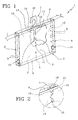
- Fig. 1 shows the structure for display 1 while it is in an operating configuration in the absence of the item to be exposed.
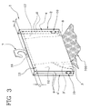
- the structure for display 1 on the contrary is associated with an item (identified with 100) that, in its preferred form of use is a demonstration fabric sample for display to the customers.
- the structure for display 1 comprises an outer structure 2 of substantially box-shaped configuration, in particular having a prismatic shape with a rectangular base.
- the outer structure 2 comprises a pair of parallel front faces 3, 3' spaced apart from each other, preferably of rectangular shape, and a pair of transverse side faces 4, 4' preferably perpendicular to the front faces 3, 3' so that said faces 3, 3', 4, 4' define a closed lateral extension in an operating configuration of the structure for display 1 that, as already said, is that shown in Figs. 1 and 3 .
- Said front 3, 3' and side 4, 4' faces delimit a hollow space 5 located at the inside of the faces themselves and suitable for at least partly holding said item 100 which is shown in the form of a fabric sample.
- the outer structure further comprises an upper face 6 which is steadily connected at least to the front faces 3, 3', in such a manner as to form an upper closure for said lateral extension of the outer structure 2 and therefore an upper closure for the hollow space 5.
- the upper face 6 is further equipped with anchoring means adapted to support the whole structure for display 1 in a steady position, for hanging structure 1 on a fixed support for example.
- the anchoring means comprises a coupling hook 7 removably in engagement with the upper face 6.
- the outer structure 2 at a lower portion thereof has an opening 8 from which item 100 partly contained in the hollow space 5 can emerge externally of the structure for display 1 and be in particular inspected and/or touched. Opening 8 preferably extends along the whole closed lateral extension of the outer structure 2 and faces downwards to enable item 100 to emerge under the action of its own weight.
- each side face 4, 4' is defined by a pair of side half-faces 9, each of which is connected to a front face 3, 3' preferably along the whole edge of the front face 3, 3' itself.
- each front face 3, 3' is connected to two side half-faces 9 which are disposed at an opposite mutual position to the front face 3, 3' itself.
- each front face 3, 3' has two opposite parallel edges to which respective side half-faces 9 are connected.
- the two half-faces 9 of each side face 4, 4' can be steadily associated with each other, in particular through connecting means 10, such as snap-fitting connecting means, pressure buttons or the like, so as to give the outer structure 2 said steady box-shaped conformation.
- connecting means 10 such as snap-fitting connecting means, pressure buttons or the like
- These snap-fitting connections 10 are of the reversible type, i.e. they can be disengaged so as to allow the two half-faces 9 of each side face 4, 4' to be decoupled and move away from each other. This enables mutual moving away of the two front faces 3, 3', each connected to a half-face 9 of each side face 4, 4', so that access to the hollow space 5 is allowed, by an operator charged with preparation or sale of item 100, for example.
- opening of the outer structure 2 is generated, which enables item 100 to be prepared in a correct manner within the hollow space 5 and/or the item position to be adjusted in a quick and practical manner.
- items 100 are generally fabric or cloth samples, they have one of their sizes much smaller than the others, i.e. a very reduced thickness, and consequently arrangement of a structure 1 for display the outer structure 2 of which has front faces 3, 3' of much bigger sizes than the side faces 4, 4' may be suitable.
- opening 8 takes a substantially rectangular and elongated shape that is adapted to offer a comfortable access opening through which the fabric to be prepared is introduced, or through which positioning of the fabric itself within the hollow space 5 can be adjusted.
- the structure for display 1 further comprises support means 11 which acts internally of the hollow space 5 to keep a portion of item 100 inside the hollow space 5 itself.
- the support means 11 is preferably fully contained in the hollow space 5 and comprises at least one tailpiece 12 facing the inside of the hollow space 5 and having a preferably rectilinear upper edge 13 acting as a support surface for item 100.
- item 100 is disposed astride said upper edge 13 and hung from the edge 13 itself under the action of its weight, until it emerges through opening 8 disposed below.
- the tailpiece 12 projects from a side half-face 9 and extends away therefrom towards the inside of the hollow space 5 and, preferably, in the direction of the opposite side face 4, 4'.
- the tailpiece 12, in the operating configuration of the structure for display 1 keeps substantially parallel to the front faces 3, 3' and spaced apart therefrom to enable the item to he housed in portions of the hollow space 5 included between the tailpiece 12 and side faces 3, 3'.
- each half-face 9 is connected to a respective tailpiece 12 and, therefore, tailpieces 12 are four in number, paired two by two.
- the two paired tailpieces 12 are substantially disposed side by side and preferably the tailpieces 12 of the two different side faces 4, 4' extend towards each other and have corresponding mutually adjacent end portions 14.
- the end portions 14 of opposite tailpieces 12 can be steadily connected to each other, preferably by a pressure connection 15 or, more generally, by a connection adapted to avoid said two end portions 14 moving away from, and/or close to each other in such a manner as to create a structure reinforcement.
- a pressure connection 15 or, more generally, by a connection adapted to avoid said two end portions 14 moving away from, and/or close to each other in such a manner as to create a structure reinforcement.
- tailpieces 12 could also give rise to an excessive deformation of the outer structure 2, thereby damaging the aesthetic appearance of same, or could even give rise to breaking of the tailpieces themselves, thus replacement of the structure for display 1 being required.
- the packaging system 1 in accordance with the above description can be made through folding of a flat blank.
- Blank 200 is preferably adapted to make both the outer structure 2 and the support means 11, and in this case is preferably made of one piece construction, by die-cutting of a sheet of a material suitable for accomplishment of the blank 200. This involves that all parts of the outer structure 2 and the support means 11 are connected with each other without a material break so as to form a monoblock body, i.e. in the absence of junctions or temporary fastening means.
- blank 200 is made of a rigid or semirigid material, i.e. a material capable of maintaining the general shape given to it by folding for example, which at the same time is not soft, i.e. has a sufficient resistance to bending to maintain an item hung.
- this material is a plastic material, more preferably a transparent one.
- this material is of a type suitable for printing, i.e. adapted to receive marks, signs and/or surface embossings, such as identification data of the item 100 to be contained, for example.
- this material is adapted to receive adhesive paper labels, on said front faces 3, 3' for example, the possibility of making said marks, signs and/or surface embossings enables application of these adhesive labels to be avoided as said application would make a differentiated recovery of the material after use difficult or even impossible (and in particular would prevent the plastic material of the structure for display and the paper material of the adhesive label to be recycled separately).
- said sheet of material adapted to form blank 200 is a thin element of a constant thickness.
- the structure for display 1 has walls of the laminar type, i.e. with a thin thickness allowing easy folding.
- blank 200 comprises a central panel 201, defining the upper face 6 of the outer structure 2, and two side panels 202, 202' opposite to the central panel 201 and defining said front faces 3, 3', respectively.
- each side panel 202, 202' is delimited by the central panel 201 by means of a respective main folding line 203, 203'.
- the central panel 201 preferably has a rectangular or square shape, and the side panels 202, 202' also preferably have a rectangular or square shape.
- the two main folding lines 203, 203' are parallel to each other.
- folding of the side panels 202, 202' relative to the central panel 201 takes place around said folding lines 203, 203' in such a manner that the side panels 202, 202' change from a common flat lying corresponding to the extended configuration of the structure for display 1, to a configuration at which they are substantially parallel and spaced apart from each other, i.e. facing each other and perpendicular to the upper face 6, taking a position corresponding to the operating configuration of the structure for display 1.
- Blank 200 further comprises at least one auxiliary panel 204 connected to a side panel 202, 202' and separated therefrom by at least one secondary folding line, which is designed to be folded on said side panel 202, 202' to define said support means 11 of item 1oo in the operating configuration of the structure for display 1, and in particular to form one of said tailpieces 12.
- each side panel 202, 202' is connected to an auxiliary panel 204 and therefore there are four auxiliary panels 204 substantially disposed at the vertices of a rectangle inscribed in blank 200.
- each auxiliary panel 204 is separated from the respective side panel 202, 202' by a pair of secondary folding lines, in particular an inner secondary folding line 205 and an outer secondary folding line 206, parallel to each other.
- Each inner secondary folding line 205 delimits in co-operation with the corresponding outer secondary folding line 206, a strip 207 that is therefore interposed between an auxiliary panel 204 and the corresponding side panel 202, 202' and defines said side half-faces 9 of the outer structure.
- each strip 207 has a major extension direction parallel to the respective secondary folding lines 205, 206 and a size, measured perpendicularly to said major extension direction, that approximately corresponds to half a corresponding thickness value "s" of the central panel 201, and therefore of the hollow space 5.
- the secondary folding lines 205, 206 are perpendicular to the main folding lines 203, 203', to such an extent that following folding of the auxiliary panels 204 around the respective secondary folding lines 205, 206 and subsequently to folding of the side panels 202, 202' around the main folding lines 203, 203', the auxiliary panels 204 face two by two so as to form said support means 11 of item 100.
- each auxiliary panel 204 has a first rectilinear edge 204' extending parallel to the main folding lines 203, 203' and facing the designed auxiliary panel 204.
- Each auxiliary panel 204 further has a second edge 204" opposite to the first edge 204' and having a curved, in particular concave, shape to reduce use of the material at regions where it would be redundant.
- this second curved edge 204" is designed to form a lower edge of a tailpiece 12 which is not required to have a solid shape but exclusively needs to perform a function of bending resistance, i.e. of support for item 100.
- Each strip 207 further has a rounded off portion 208 preferably extending between the respective secondary folding lines 205, 206 and disposed at the first end 204' of the corresponding auxiliary panel 204.
- This rounded off portion has an oblique flap 209 originating from intersection "P1" between the inner secondary folding line 205 and the corresponding main folding line 203, 203' and terminates at the intersection "P2" between the outer secondary folding line 206 and the first edge 204' of the auxiliary panel 204.
- the oblique flap 209 forms a reduction in width in passing from a width "L1" of the respective side panel 202, 202' to a width "L2" of the respective auxiliary panel 204.
- This width reduction in the operating configuration of the structure for display 1, forms a corresponding size of an interspace "C" between the upper face 6 of the structure for display 1 and the upper edge 13 of the tailpieces 12 which is necessary to accommodate item 100 and keep it astride said tailpieces 12.
- slots 210 and projections 211 are designed to form slots 210 and projections 211 respectively, in such a manner that the slot 210 associated with an auxiliary panel 204 is susceptible of engagement with a corresponding projection 211 of the corresponding auxiliary panel 204, i.e. the auxiliary panel 204 that is designed to face it.
- Slots 210 and projections 211 define the already mentioned pressure connections adapted to keep the two adjacent half-faces 9 of each side face 4, 4' steadily connected, although in a removable manner, in the operating configuration of the structure for display 1.
- slit 212 adapted to be engaged by the coupling hook 7 by pressure coupling or snap-fitting for example.
- slit 212 can have such sizes as to enable the coupling hook 7 to be inserted from a portion of the blank 200 designed to face the inside of the hollow space 5, so that the coupling hook 7, once inserted, generates an efficient support action and has no tendency to slip off outwardly. This can be obtained by an undercut 16 ( Figs. 1 , 3 , 5a ) in the lower part of hook 7, which has bigger sizes than slit 212 and therefore remains inside the hollow space 5 preventing the hook 7 from slipping off or separating from the outer structure 2.
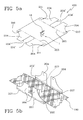
- a method of packaging an item (or of folding and/or preparing the structure for display) in accordance with the present invention is now illustrated by way of example and according to the sequence of figures from 5a to 5d.
- the coupling hook 7 is inserted into slit 212 until the undercut 16 of said hook 7 abuts against blank 200. This is convenient when hook 7 is provided with said undercut 16 as it would not be possible or in any case easy to insert hook 7 into slit 212 when the structure for display 1 is in the operating configuration.
- the blank 200 is such disposed that only a surface thereof designed to face the inside of the hollow space 5 of the structure for display to be made is visible.
- auxiliary panels 204 are folded along the inner secondary folding lines 205 until said panels are disposed at right angles to the remaining parts of blank 200, while item 100 is laid on the side panels 202, 202', in the manner shown in Fig. 5b .
- the item to be packaged 100 can be in turn contained in a tubular plastic envelope for protection; in other words, package 1 can be also used for packing an item already protected (partly or fully covered) with flexible plastic material.
- laying of item 100 can also take place before the step of folding the auxiliary panels 204, or simultaneously therewith, so that the final operation of folding the auxiliary panels 204 takes place by making the same face the already laid item 100.
- Folding of the auxiliary panels 204 is completed by further folding the same around the outer secondary folding lines 206, so that the strips 207 perpendicular to the side panels 202, 202' are formed.
- the auxiliary panels 204 reach a lying position parallel to the side panels 202, 202' and lay down on the item 100 already put thereon, as shown in Fig. 5c .
- a substantially planar configuration is obtained and, during the last-mentioned step, also projections 211 and slots 210 are defined, still in accordance with the view in Fig. 5c .
- said junction of the end portions 14 of the tailpieces 12 can be made, should this be provided.
- Replacement and/or any modification in the positioning of item 100 can take place by bringing the structure for display 1 back to the extended configuration, i.e. the configuration taken by blank 200, and then bringing the structure for display back again to its operating configuration, i.e. reusing the same packaging system being the object of the invention.
- Package 1 in accordance with the above description is suitable for displaying items such as fabrics, cloths, linen or, more generally, any soft goods that can be hung from a horizontal support of the type of the above described tailpieces and must be inspected and touched, by potential purchasers for example.
- the present invention achieves the intended purposes and solves the drawbacks present in the known art.
- a manufacture starting from a flat blank, exclusively by means of folding steps, enables the industrial packaging processes to be greatly simplified as they only require a blank to be made, for example by die-cutting from a plastic sheet, and a subsequent short sequence of folding steps to be carried out. Consequently, the manufacturing costs are very reduced, also in connection with use of plastic material that has low costs in terms of raw materials and working processes.
- the structure for display can be reused, as it is sufficient to unfold and extend the outer structure to enable access to the hollow space and replacement of the item; the box-shaped conformation of the structure for display can be then obtained again in a very simple manner.
- the structure for display gives rise to covering of most of the displayed item, leaving only a small portion thereof uncovered to enable it to be touched; thus use of protective plastic covers like those described in the known art is eliminated.
- a structure for display of the above described type is suitable for supporting different types of items also different from those listed above, possibly by carrying out small modifications.
- the structure for display can also be used for articles of clothing such as shirts, jackets, neck-ties, trousers.
Landscapes
- Engineering & Computer Science (AREA)
- Mechanical Engineering (AREA)
- Packaging Of Annular Or Rod-Shaped Articles, Wearing Apparel, Cassettes, Or The Like (AREA)
Priority Applications (1)
| Application Number | Priority Date | Filing Date | Title |
|---|---|---|---|
| EP07425316A EP1995184A1 (fr) | 2007-05-24 | 2007-05-24 | Structure portable pour exposer des articles, particulièrement des articles textiles |
Applications Claiming Priority (1)
| Application Number | Priority Date | Filing Date | Title |
|---|---|---|---|
| EP07425316A EP1995184A1 (fr) | 2007-05-24 | 2007-05-24 | Structure portable pour exposer des articles, particulièrement des articles textiles |
Publications (1)
| Publication Number | Publication Date |
|---|---|
| EP1995184A1 true EP1995184A1 (fr) | 2008-11-26 |
Family
ID=38441936
Family Applications (1)
| Application Number | Title | Priority Date | Filing Date |
|---|---|---|---|
| EP07425316A Withdrawn EP1995184A1 (fr) | 2007-05-24 | 2007-05-24 | Structure portable pour exposer des articles, particulièrement des articles textiles |
Country Status (1)
| Country | Link |
|---|---|
| EP (1) | EP1995184A1 (fr) |
Cited By (2)
| Publication number | Priority date | Publication date | Assignee | Title |
|---|---|---|---|---|
| US20110253567A1 (en) * | 2010-04-19 | 2011-10-20 | Sharon Rae Cossey | Gift bag operable with one or more hangers |
| KR101650864B1 (ko) * | 2015-07-23 | 2016-08-25 | 주식회사 근화 | 의류 정리 케이스 |
Citations (4)
| Publication number | Priority date | Publication date | Assignee | Title |
|---|---|---|---|---|
| DE8034641U1 (de) * | 1980-12-24 | 1981-09-03 | Franz Falke-Rohen Strumpfwarenfabriken Gmbh, 5948 Schmallenberg | Strumptf- insbesondere Feinstrumpfpackung |
| FR2780625A1 (fr) * | 1998-07-02 | 2000-01-07 | Dim Sa | Cavalier plat de presentation pour article textile plat tel qu'une socquette |
| US20040112772A1 (en) * | 2001-03-30 | 2004-06-17 | Keiji Kimura | Packaging material for commodity |
| US20070045130A1 (en) * | 2005-08-30 | 2007-03-01 | Cin Kim | Display unit adapted to secure cuff links |
-
2007
- 2007-05-24 EP EP07425316A patent/EP1995184A1/fr not_active Withdrawn
Patent Citations (4)
| Publication number | Priority date | Publication date | Assignee | Title |
|---|---|---|---|---|
| DE8034641U1 (de) * | 1980-12-24 | 1981-09-03 | Franz Falke-Rohen Strumpfwarenfabriken Gmbh, 5948 Schmallenberg | Strumptf- insbesondere Feinstrumpfpackung |
| FR2780625A1 (fr) * | 1998-07-02 | 2000-01-07 | Dim Sa | Cavalier plat de presentation pour article textile plat tel qu'une socquette |
| US20040112772A1 (en) * | 2001-03-30 | 2004-06-17 | Keiji Kimura | Packaging material for commodity |
| US20070045130A1 (en) * | 2005-08-30 | 2007-03-01 | Cin Kim | Display unit adapted to secure cuff links |
Cited By (2)
| Publication number | Priority date | Publication date | Assignee | Title |
|---|---|---|---|---|
| US20110253567A1 (en) * | 2010-04-19 | 2011-10-20 | Sharon Rae Cossey | Gift bag operable with one or more hangers |
| KR101650864B1 (ko) * | 2015-07-23 | 2016-08-25 | 주식회사 근화 | 의류 정리 케이스 |
Similar Documents
| Publication | Publication Date | Title |
|---|---|---|
| US4590610A (en) | Hanging product display packages | |
| US4190151A (en) | Display hanger | |
| US7762392B2 (en) | Shirt boxes and arrangements of articles of clothing therein | |
| US7918338B2 (en) | Convertible hangtag display | |
| US6508357B1 (en) | Fold package with pressure-sensitive hanging tab | |
| US20100181311A1 (en) | Box blank | |
| US9102442B2 (en) | Container with presentation element | |
| US8177060B2 (en) | Retail box for displaying a tie | |
| EP1995184A1 (fr) | Structure portable pour exposer des articles, particulièrement des articles textiles | |
| KR200461520Y1 (ko) | 의류 접이용 포장백 | |
| US20110253567A1 (en) | Gift bag operable with one or more hangers | |
| CA2504294A1 (fr) | Systeme de fourniture d'album de decoupures | |
| GB2520640A (en) | Display wrapper for garments hung on a garment hanger | |
| US20140116912A1 (en) | Container for packaging a folded fabric product | |
| JP5956469B2 (ja) | 吊り下げ式商品ディスプレイシステム | |
| JP4871199B2 (ja) | 衣類用パッケージ | |
| US20050098468A1 (en) | Hanging display package | |
| JP3163924U (ja) | 肌着陳列用パッケージ | |
| CN223116897U (zh) | 一种翻折式包装盒 | |
| JP3223442U (ja) | 布帛商品吊り下げ具 | |
| JP5137531B2 (ja) | 肩紐つき衣類商品パッケージ | |
| WO2008104123A1 (fr) | Tableau d'affichage pour accrocher des objets laminés | |
| JP3062023U (ja) | 商品展示用口紙 | |
| GB2350345A (en) | Packaging means for tools having head and handle portions | |
| JP3063692U (ja) | 包装用テ―プ |
Legal Events
| Date | Code | Title | Description |
|---|---|---|---|
| PUAI | Public reference made under article 153(3) epc to a published international application that has entered the european phase |
Free format text: ORIGINAL CODE: 0009012 |
|
| AK | Designated contracting states |
Kind code of ref document: A1 Designated state(s): AT BE BG CH CY CZ DE DK EE ES FI FR GB GR HU IE IS IT LI LT LU LV MC MT NL PL PT RO SE SI SK TR |
|
| AX | Request for extension of the european patent |
Extension state: AL BA HR MK RS |
|
| AKX | Designation fees paid | ||
| REG | Reference to a national code |
Ref country code: DE Ref legal event code: 8566 |
|
| STAA | Information on the status of an ep patent application or granted ep patent |
Free format text: STATUS: THE APPLICATION IS DEEMED TO BE WITHDRAWN |
|
| 18D | Application deemed to be withdrawn |
Effective date: 20090527 |