EP1995363B1 - Procédé de tricotage de tissu et dispositif de conception - Google Patents
Procédé de tricotage de tissu et dispositif de conception Download PDFInfo
- Publication number
- EP1995363B1 EP1995363B1 EP07736914.8A EP07736914A EP1995363B1 EP 1995363 B1 EP1995363 B1 EP 1995363B1 EP 07736914 A EP07736914 A EP 07736914A EP 1995363 B1 EP1995363 B1 EP 1995363B1
- Authority
- EP
- European Patent Office
- Prior art keywords
- knitting
- needle
- yarn
- stitch
- fabric
- Prior art date
- Legal status (The legal status is an assumption and is not a legal conclusion. Google has not performed a legal analysis and makes no representation as to the accuracy of the status listed.)
- Not-in-force
Links
- 238000009940 knitting Methods 0.000 title claims description 357
- 239000004744 fabric Substances 0.000 title claims description 71
- 238000000034 method Methods 0.000 title claims description 27
- 238000013461 design Methods 0.000 title claims description 15
- 238000012546 transfer Methods 0.000 description 41
- 239000011435 rock Substances 0.000 description 6
- 238000012545 processing Methods 0.000 description 5
- 239000000969 carrier Substances 0.000 description 4
- 238000004891 communication Methods 0.000 description 4
- 238000010586 diagram Methods 0.000 description 4
- 230000007246 mechanism Effects 0.000 description 4
- 230000000694 effects Effects 0.000 description 3
- 230000009471 action Effects 0.000 description 2
- 230000015572 biosynthetic process Effects 0.000 description 2
- 230000008569 process Effects 0.000 description 2
- 230000008859 change Effects 0.000 description 1
- 238000009434 installation Methods 0.000 description 1
- 238000003672 processing method Methods 0.000 description 1
- 230000004044 response Effects 0.000 description 1
Images


Classifications
-
- D—TEXTILES; PAPER
- D04—BRAIDING; LACE-MAKING; KNITTING; TRIMMINGS; NON-WOVEN FABRICS
- D04B—KNITTING
- D04B7/00—Flat-bed knitting machines with independently-movable needles
- D04B7/24—Flat-bed knitting machines with independently-movable needles for producing patterned fabrics
- D04B7/26—Flat-bed knitting machines with independently-movable needles for producing patterned fabrics with colour patterns
-
- D—TEXTILES; PAPER
- D04—BRAIDING; LACE-MAKING; KNITTING; TRIMMINGS; NON-WOVEN FABRICS
- D04B—KNITTING
- D04B1/00—Weft knitting processes for the production of fabrics or articles not dependent on the use of particular machines; Fabrics or articles defined by such processes
-
- D—TEXTILES; PAPER
- D04—BRAIDING; LACE-MAKING; KNITTING; TRIMMINGS; NON-WOVEN FABRICS
- D04B—KNITTING
- D04B1/00—Weft knitting processes for the production of fabrics or articles not dependent on the use of particular machines; Fabrics or articles defined by such processes
- D04B1/10—Patterned fabrics or articles
- D04B1/12—Patterned fabrics or articles characterised by thread material
- D04B1/126—Patterned fabrics or articles characterised by thread material with colour pattern, e.g. intarsia fabrics
-
- D—TEXTILES; PAPER
- D04—BRAIDING; LACE-MAKING; KNITTING; TRIMMINGS; NON-WOVEN FABRICS
- D04B—KNITTING
- D04B15/00—Details of, or auxiliary devices incorporated in, weft knitting machines, restricted to machines of this kind
- D04B15/32—Cam systems or assemblies for operating knitting instruments
- D04B15/36—Cam systems or assemblies for operating knitting instruments for flat-bed knitting machines
- D04B15/362—Cam systems or assemblies for operating knitting instruments for flat-bed knitting machines with two needle beds in V-formation
- D04B15/365—Cam systems or assemblies for operating knitting instruments for flat-bed knitting machines with two needle beds in V-formation with provision for loop transfer from one needle bed to the other
Definitions
- the present invention relates to a method for knitting a fabric and a design device to, in intarsia patterns, floating stitches, and the like, capture a knitting yarn in the hook of a knitting needle when the knitting yarn is let loose to avoid engagement in the knitting needle and be fed as a cross-over yarn.
- a flat knitting machine is used to knit fabrics including an intarsia pattern and the like by changing over a plurality of knitting yarns in the same knitting course (for example, see Patent Citation 1).
- Knitting yarns used for knitting fabrics on flat knitting machines are fed to knitting needles from a yarn feeding member such as a yarn carrier, which moves along a needle bed gap in cooperation with the fabric knitting operation of the knitting needles.
- the intarsia pattern and the like to be knitted are in the form of being fitted in the fabric serving as a ground. Consequently, at the start portion and the end portion of the intarsia pattern and the like, yarn in and yarn out of a knitting yarn different from the ground fabric are carried out.
- the position of yarn feeding from a yarn carrier and the like floats from the needle bed gap at the end part where knitting of an intarsia pattern and the like starts, thereby making it difficult to capture the fed knitting yarn in the hook of the knitting needle.
- the cross-over yarn might be erroneously captured in a knitting needle that is knitting the fabric and thus be knitted into the fabric or might be entangled to the detriment of the knitting operation.
- the problem of floating of the cross-over yarn from the needle bed gap and difficulty in capturing in the knitting needle occurs not only in the intarsia-pattern knitting but also in fabrics of the floating stitch.
- processing is carried out as knitting the cross-over yarn into the fabric such as by a tuck in the cross-over section, thus preventing the cross-over yarn from floating from the needle bed gap.
- knitting the cross-over yarn into the fabric by a tuck and the like requires the work of removing the knitted cross-over yarn portion in the subsequent process.
- a yarn processing method and a knitting method that temporarily capture the knitting yarn to be a cross-over yarn with the use of knitting needles in the cross-over section and release the captured cross-over yarn after knitting of a plurality of courses (see, for example, Patent Citations 2 and 3).
- the cross-over yarn floats from the needle bed gap. Therefore, when the cross-over section is elongated, the number of capturing knitting needles must be increased.
- a method for capturing the cross-over yarn such that instead of engaging the cross-over yarn in the hook of the knitting needle, the knitting needle is guided to the lower side of the hook and held (see, for example, Patent Citation 4).
- the requisite of this method is that the movements of the knitting needle and yarn feeding member are individually controllable, which necessitates mounting of a new cam mechanism in the flat knitting machines, by which fabrics are knitted while moving a carriage mounting therein a cam mechanism along the needle bed gap with the accompaniment of the yarn carrier.
- the present invention provides a method for knitting a fabric on a flat knitting machine provided with at least a pair of front and rear needle beds opposed to one another across a needle bed gap, each of the needle beds being provided with a multiplicity of latch needles as knitting needles, which comprises:
- the held stitch loop is transferred to the knitting needle of the one needle bed from a fabric belonging to the other needle bed; and after the split knit, the newly formed stitch loop is removed from the knitting needle of the one needle bed.
- the knitting yarn is used for knitting an inner area of the fabric and becomes the cross-over yarn during yarn out; the split knit is carried out in the vicinity of an end portion of the fabric; and after the split knit, the newly formed stitch loop is removed from the knitting needle of the other needle bed after knitting of a predetermined number of courses.
- the stitch loop newly formed by the split stitch is removed from the knitting needle of the one needle bed after, subsequent to the split stitch, a stitch is formed on a knitting needle different from the knitting needle used for the split stitch.
- the stitch loop subjected to the split stitch into the knitting needle of the other needle bed, or a stitch loop knitted following the split stitch loop is transferred to the one needle bed side to stop ravel.
- the knitting yarn is fed in such a manner that the knitting yarn becomes the cross-over yarn from a portion kitted before the plurality of courses of the fabric; in a knitting course where the split knit is carried out, a portion where the knitting yarn crosses between the needle beds is formed in the vicinity of the end portion of the fabric; and the crossing portion is released after the cross-over yarn is fed in and captured in the knitting needle carrying out the split knit through the crossing portion.
- the present invention provides a design device of a fabric for creating knitting data to knit a fabric on a flat knitting machine, the flat knitting machine being provided with at least a pair of front and rear needle beds opposed to one another across a needle bed gap, each of the needle beds being provided with a multiplicity of latch needles as knitting needles, the knitting data created by the design device causing the flat knitting machine to execute a method which comprises; carrying out a split knit of a stitch loop held in the knitting needle of the one needle bed into a knitting needle of the other needle bed; and capturing a knitting yarn as a newly formed knitting loop in a hook of a knitting needle of the one needle bed, the knitting yarn serving as a cross-over yarn by being let loose over a distance so as to avoid engagement of the knitting yarn in knitting needles, the distance makes it difficult to capture the knitting yarn in a hook of a knitting needle which independently carrying out a stitch forming operation.
- a multiplicity of latch needles are disposed on a pair of front and rear needle beds as knitting needles, and even the knitting yarn in the cross-over yarn state floating from the needle bed gap is guided inside the hook when a split stitch between the needle beds causes the stitch loop subjected to the split into an opposite needle bed to close the latch in the needle bed gap, thereby making it possible to surely capture the knitting yarn.
- the knitting yarn is definitely captured and knit a stable fabric.
- the stitch loop subjected to the split stitch is one that is transferred in advance from the needle bed to which the fabric belongs to the opposite needle bed, which makes it possible to return the transferred stitch loop to the original needle bed side as the split stitch.
- the new stitch loop is removed from the knitting needle to which the transfer was carried out, thereby eliminating the need for processing of the stitch loop newly formed by the split stitch in a subsequent process.
- the cross-over yarn is surely captured in the hook of the knitting needle in the vicinity of the end portion of the fabric, and in predetermined course knitting, the cross-over yarn is able to be held to prevent it from floating between the needle bed gap.
- the stitch loop newly formed by the split stitch is removed after a stitch loop following the split stitch is formed on a knitting needle different from the knitting needle of the stitch loop that was used for the split stitch.
- the stitch loop follows the split stitch can be returned to the split starting side by transfer instead of being removed so as to be utilized effectively to prevent a ravel.
- the state in which the knitting yarn fed in a state of a cross-over yarn, which avoids engagement in the knitting needle, floats from the needle bed gap varies depending on differences in the position of a portion of the knitting yarn where the preceding knitting course finished.
- a portion where the knitting yarn crosses the needle beds is formed, and therefore, the cross-over yarn is fed to the knitting needle that carries out the split stitch through the crossing portion.
- the crossing portion is rendered a starting point of yarn feeding to have a uniform condition for capturing the knitting yarn in the hook of the knitting needle, thereby making it possible to ensure the capture.
- knitting data can be created in such a manner that when a knitting yarn not engaged in the knitting needle becomes a cross-over yarn by floating from the needle bed gap, such knitting yarn can be surely captured in the hook of the knitting needle by split stitch.
- Fig. 1 is one embodiment of the present invention showing a state in which a knitting yarn is captured in the hook of a knitting needle with the use of a knitting operation of split stitch.
- a driving mechanism of knitting needles 3 and 4 is provided that is capable of, while transferring a stitch loop formed in the preceding course between the needle beds, forming a new stitch loop also on the knitting needle on the stitch-transferring side.
- the front needle bed 1 and the rear needle bed 2 are opposed to one another across a needle bed gap 5, and able to advance and retire the tip sides of the knitting needles 3 and 4 back and forth with respect to the needle bed gap 5.
- the knitting needles 3 and 4 on their tip sides are respectively provided with hooks 3a and 4a and latches 3b and 4b.
- the knitting needle 3 at its midpoint is provided with a clip 3c.
- a yarn carrier 6 is movably provided in a direction perpendicular to the paper surface and feeds knitting yarn 7 through a yarn feeding port at the distal end.
- a stitch loop 8 is formed by the knitting operation of the knitting needles 3 and 4, and as the knitting proceeds, the stitch loop 8 parts from the knitting needles 3 and 4 to form a fabric 9 and hangs below the needle bed gap 5 by dead weight and various kinds of biasing.
- a new stitch loop is also formed on the hook 3a of the knitting needle 3 from a knitting yarn 7 fed from the yarn carrier 6.
- Fig. 1(a) shows a state in which after the stitch loop 8 is held at the clip 3c portion of the knitting needle 3 of the front needle bed 1 and is allowed to advance to the needle bed gap 5, the hook 4a of the knitting needle 4 of the rear needle bed 2 is allowed to go into the clip 3c portion and the stitch loop 8 is engaged in the hook 4a.
- the stitch loop 8 parts from the clip 3c and comes close to the tip of the latch 3b in an open state, since the stitch loop 8 is engaged in the hook 4a of the knitting needle 4 of the rear needle bed 2.
- the portion of the stitch loop 8 engaged in the knitting needle 3 comes around the tip of the knitting needle 3 along the circumferential portion of the latch 3b that is closing the hook 3a, thus parting from the knitting needle 3.
- the parting stitch loop 8 is engaged only in the hook 4a at the tip of the knitting needle 4 to end up as a stitch loop on the rear needle bed 2 side while being a knocked-over former loop for the stitch loop newly formed on the knitting needle 3.
- Fig. 2 shows one example of a cam system 10 that carries out the knitting operation to the knitting needle 3 of the front needle bed 1, which carries out transfer by the split stitch operation shown in Fig. 1 .
- this cam system is one of a plurality of sets mounted to the carriage along the needle bed gap 5, and is shown with the needle bed gap side upward.
- a portion closer to the needle bed gap may be indicated as “upper” and a portion away from the needle bed gap may be indicated as “lower”.
- a ground board 11 of the carriage facing the needle bed is provided with a stitch forming cam rock 15 including a needle raising cam 12 and stitch cams 13 and 14, and a stitch transferring cam rock 18 including a stitch receiving transfer cam 16 and a transfer cam 17 for both transfer and reception.
- the stitch cams 13 and 14 can be displaced along a direction parallel to slanted cam surfaces 13a and 14a so as to adjust the stitch density.
- the needle raising cam 12 has a lower fixed portion 19 and an upper movable portion 20.
- the movable portion 20 provided with a mechanism not shown, protrudes and recedes with respect to the ground board 11 alternately with the transfer cam 17 for both transfer and reception in such a manner that when one protrudes, the other recedes.
- the movable portion 20 is provided with a butt guiding groove 20a.
- the butt guiding groove 20a is bent in a mountainous form with its center portion approaching the needle bed gap side, and links to the slope of the fixed portion 19 through a horizontal shoulder portion 20b on both sides of the groove.
- the fixed portion 19 on its upper center portion is provided with the stitch receiving transfer cam 16 in a freely protruding/receding manner.
- the stitch receiving transfer cam 16 is symmetrical, both sides of which are inclined in such a manner that a portion closer to the center becomes deeper.
- the transfer cam 17 for both transfer and reception above the needle raising cam 12 is roughly in the form of mountainous triangles with two peaks disposed side by side. On the upper edge side, the transfer cam 17 guides a knitting needle butt on the stitch transferring side, and on the lower edge side, guides a knitting needle butt on the stitch receiving side. Above the transfer cam 17 for both transfer and reception, a transfer guide cam 21 is provided, on both sides of which continue needle guide cams 22.
- the movable portion 20 of the needle raising cam 12 is kept in the receding state as indicated by a chain double-dashed line while the transfer cam 17 for both transfer and reception is kept in the protruding state as indicated by a solid line.
- the knitting needles 3 and 4 are provided with two butts for receiving driving for the knitting operation by the cam system 10, with an upper butt 23 being acted upon by the stitch transferring cam rock 18 and a lower butt 24 being acted upon by the stitch forming cam rock 15. Assuming that the carriage provided with the cam system 10 runs leftward in the figure, the upper butt 23 and the lower butt 24 of the knitting needle 3 on the stitch transferring side move along the courses indicated by chain double-dashed lines.
- the positions of the upper butt 23 and the lower butt 24 corresponding to Fig. 1(a), 1(b), and 1(c) are respectively indicated by 23a, 23b, and 23c; 24a, 24b, and 24c.
- the position shown as the yarn carrier 6 is represented by the position at which the knitting yarn 7 from the yarn feeding port of the yarn carrier 6 is received in the hook 3a of the knitting needle 3.
- Fig. 3 shows a state in which the knitting needle 4 of the rear needle bed 2 is made to perform a knitting operation for a stitch receiving side by the split stitch operation shown in Fig. 1 with the use of the cam system 10 of Fig. 2 .
- the cam system 10 of Fig. 3 is mounted to the carriage of the rear needle bed 2. Therefore, for convenience of explanation, Fig. 3 is shown to be symmetrical to Fig. 2 with the needle bed gap side down. Corresponding portions in Figs. 2 and 3 are denoted by the same numerals and overlapping explanations will be omitted in Fig. 3 .
- the movable portion 20 of the needle raising cam 12 is kept in the receding state as indicated by a chain double-dash line while the transfer cam 17 for both transfer and reception is kept in the protruding state as indicated by a solid line.
- the knitting needle 4 is also acted upon by pressers 25, 26, and 27, though description of which is omitted in Fig. 2 .
- the cam system 10 selects the position of the knitting needle 4 among three positions to be acted upon by one of the pressers 25, 26, and 27, as disclosed in, for example, Fig. 1 of Japanese Examined Patent Application Publication No. H02-10262 .
- the knitting needles 3 and 4 are basically equivalent to those disclosed in Fig. 2 of Japanese Examined Patent Application Publication No. H02-10262 .
- the pressers 25, 26, and 27 can be individually switched into or out of action.
- the intermediate presser 27 is switched out of action as indicated by a chain double-dashed line.
- the pressers 25 and 26 are made to act upon the knitting needle 4
- the lower butt 24 of the knitting needle 4 is no longer acted upon by the fixed portion 19 but is acted upon by the stitch receiving transfer cam 17 at the center to advance to the needle bed gap side.
- the upper butt 23 comes in contact with the lower edge of the transfer cam 17 for both transfer and reception and descends along the guide surface formed on the lower edge.
- Fig. 4 shows a state in which the knitting needle 3 is made to perform a knitting operation of a knit with the use of the cam system 10 of Fig. 2 .
- the tip of the knitting needle 3 is temporarily advanced to the needle bed gap 5 to a clear position where the stitch loop 8 retracts behind the latch 3b.
- the stitch loop 8 that continues into the fabric 9 stays in the vicinity of the tip of the front needle bed 1, since the fabric 9 is biased below the needle bed gap 5.
- Fig. 4(a) shows a state in which the knitting needle 3 that was allowed to advance into the needle bed gap 5 to the clear position is pulled back to the front needle bed 1 and is fed a knitting yarn 7 from the yarn carrier 6. As shown in Fig.
- Fig. 5 shows a switching state of the cam system 10 when the knitting operation of a knit as shown in Fig. 4 is performed.
- the movable portion 20 of the needle raising cam 12 is kept in the protruding state as indicated by a solid line while the transfer cam 17 for both transfer and reception is kept in the receding state as indicated by a chain double-dashed line.
- the positions of the upper butt 23 and the lower butt 24 corresponding to Fig. 4(a), 4(b), and 4(c) are respectively indicated by 23a, 23b, and 23c; 24a, 24b, and 24c.
- the position shown as the yarn carrier 6 is represented by the position at which the knitting yarn 7 from the yarn feeding port of the yarn carrier 6 is received in the hook 3a of the knitting needle 3.
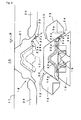
- Fig. 6 shows a simplified diagram of an example of the fabric 9.
- a pattern area 9xa of A is knitted
- a pattern area 9yb of B is knitted in a pattern area 9ya of A.
- a pattern area 9za of A is knitted in such fabric 9.
- processing of cross-over yarn is required at the time of yarn feeding at an edge portion 28 of the pattern area 9yb and at the time of yarn retrieval from an edge portion 29.
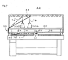
- Fig. 7 schematically shows a structure of a flat knitting machine 30 that knits the fabric 9.
- the front needle bed 1 is provided with a carriage 31 mounted with a cam system capable of knitting, transfer, split stitch, and the like.
- the carriage 31 selectively takes yarn carriers 6a and 6b that can travel along a yarn guide rail 32 provided above the needle gap, and travels reciprocatedly in the longitudinal direction of the needle bed. It is assumed that the pattern area of A of Fig. 6 is knitted with a knitting yarn 7a fed from the yarn carrier 6a and the pattern area of B is knitted with a knitting yarn 7b fed from the yarn carrier 6b.
- the knitting yarns 7a and 7b are fed from cones 33a and 33b disposed upright on a cone stand plate 33 to the yarn carriers 6a and 6b, respectively, at a substantially constant tension through a yarn tension device 34 and a yarn feeding device 35.
- a gripper 36 provided at the end portion of the needle bed.
- the end portion of the knitting yarn 7b is grasped by the gripper 36 until knitting of the edge portion 28 of the pattern area 9yb of the Y section starts.
- the need for capturing the knitting yarn 7 at a high position in the hook 3a occurs not only in knitting of intarsia patterns but also in floating stitches, where knitting is carried out after misses to the knitting needle are continued, and in the case where knitting of an area of an independent fabric such as a pocket newly starts in a fabric. Also in these cases, utilizing the split stitch can capture the knitting yarn 7 surely in the hook 3a.
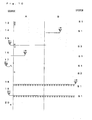
- Figs. 8 , 9 , and 10 each show a state in which knitting of the X section in the wale direction is finished and knitting of the Y and Z sections for the fabric 9 of Fig. 6 is carried out.
- the numbers shown under "course" on the left side of each figure indicate relative course numbers. In the odd-number courses, the carriage runs leftward while in the even-number courses the carriage runs rightward.
- the symbols shown under "system” on the right side of each figure each show which cam system 10 is used when each carriage 31 mounts thereon three cam systems 10 such as those shown in Figs. 2 , 3 , and 5 .
- S1 indicates a system on the preceding side
- S2 indicates an intermediate system
- S3 indicates a system on the following side.
- the cam system 10 on the left side is designated as S1 and the cam system 10 on the right side is designated as S3 while when the carriage runs rightward, the cam system 10 on the right side is designated as S1 and the cam system 10 on the left side is designated as S3.
- the use of the cam system is shown by way of example.
- the numerical characters on and after the course 9 do not mean the courses on and after the 9th course relative to the course 1.
- the last course knitting in the X section in the wale direction is carried out by the knitting yarn 7a at the front needle bed 1.
- a stitch transfer is carried out from the front needle bed 1 to the rear needle bed 2 in the pattern area of A. This stitch transfer is for the purpose of forming a crossing portion in the needle bed gap 5 using the knitting yarn 7a.
- the position where the crossing portion is formed is preferably in the vicinity of the edge portion of the knitting width of the fabric 9.
- the first course knitting of the Y section in the wale direction starts.
- the yarn carrier 6b that feeds the knitting yarn 7b stands by on the left side of the front needle bed 1 as shown in Fig. 7 .
- the knitting yarn 7b links not to the gripper 36 but to the edge portion of the knitted pattern area of B, from the yarn feeding port at the distal end of the yarn carrier 6b.
- the yarn carrier 6b indicated as "b" is took rightward, the knitting yarn 7b is fed to the edge portion 28 of Fig. 6 after being engaged in the crossing portion formed in the course 1.
- split stitch is carried out. As described above, since the split stitch is used, even when the position of the knitting yarn 7b fed from the yarn carrier 6b is high, the knitting yarn 7b can be surely captured in the hook 3a of the knitting needle 3.
- the yarn carrier 6b runsa rightward by the system S1, and hooking to the rear needle bed 2 is transferred to the front needle bed 1 by the system S2.
- a tension to the knitting yarn 7b in the opposite direction by the system S1 and carrying out a stitch transfer by the system S2 relative to the hooking a twisted stitch can be formed at the edge portion of the pattern area side of A of the front needle bed 1.
- the yarn carrier 6b is advanced to the pattern area side of A by the system S1, and furthermore, a stitch transfer is carried out such that the stitch transferred to the knitting needle 4 of the rear needle bed 2 in the course 1 is returned to the knitting needle 3 of the front needle bed 1.
- a stitch transfer is carried out such that the stitch transferred to the knitting needle 4 of the rear needle bed 2 in the course 1 is returned to the knitting needle 3 of the front needle bed 1.
- the course knitting of the pattern area of B is carried out by hauling the yarn carrier 6b by the system S1.
- knitting of the pattern area of A is carried out by hauling the yarn carrier 6a by the system S2.
- the stitch loop that was subjected to the split stitch in the course 2 and is held in the knitting needle 4 of the rear needle bed 2 at the edge portion 28 of the pattern area of B is transferred to the knitting needle 3 of the front needle bed 1.
- ravel stopping can be carried out for the edge portion 28. Although this ravel stopping is carried out with the use of the stitch loop subjected to the split stitch, this method of ravel stopping is shown by way of example and other methods than this are possible.
- the stitch loop subjected to the split stitch may be removed.
- Simply removing the stitch loop subjected to the split stitch eventually forms a stitch loop that is similar to one of a knit and is able to be used in the case where the position of the yarn feeding position is heightened due to yarn feeding, floating stitch, and the like.
- subsequent to the yarn feeding in the same knitting course, it is possible to form a stitch loop on a knitting needle different from the knitting needle used for the split stitch and then remove the stitch loop subjected to the split stitch.
- the stitch loop is temporarily transferred to carry out a split stitch and a stitch loop newly formed by the split stitch is removed, then eventually this returns to the state before the stitch transfer.
- the stitch loop at the edge portion of the pattern area of A is transferred to carry out a split stitch, and after forming a stitch loop in the pattern area of B in the knitting course that is the same as or subsequent to the knitting course where the increment was carried out, the stitch loop newly formed by split stitch at the edge portion of the pattern area of A is removed, then the stitch loop in the pattern area of A returns to the state before the stitch transfer, thereby securing yarn feeding for knitting of the pattern area of B.
- the pattern areas of A and B are knitted by repeating a required number of courses while hauling the yarn carriers 6a and 6b by systems S1 and S2.
- the stitch loop transferred in the course 13 is subjected to a split stitch to the knitting needle 3 side of the front needle bed 1. This can surely capture a cross-over yarn generated by yarn feeding from the edge portion 29 of the pattern area of B in the vicinity of the selvedge of the fabric 9 and prevent floating at the needle bed gap 5.
- the yarn carrier 6b is returned to a position that is closer to the side of the pattern area of B than the positions of the knitting needles 3 and 4 where the split stitch was carried out.
- the stitch loop that is a former loop relative to the newly formed stitch loop is the stitch loop transferred in the course 13, and part of this stitch loop is engaged in the front needle bed 1 side by the split stitch in the course 15, and therefore, this stitch loop is absorbed in the stitch loop of the knitting needle 3 of the front needle bed 1, and as a result, the stitch transfer in the course 13 returns to the original in the course 17.
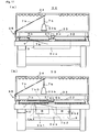
- Fig. 11 shows effects of forming the crossing portion in the course 1 of Fig. 8 .
- Fig. 11(a) shows a state in which the carriage 31 hauls the yarn carrier 6a leftward in the course 1.
- the yarn carrier 6b which feeds the knitting yarn 6b, waits outside the knitting width of the fabric 9.
- the knitting yarn 7b is the cross-over yarn from the yarn feeding port at the distal end of the yarn carrier 6b.
- Fig. 11(b) shows a state in which the carriage hauls the yarn carrier 6b rightward in the course 2 after a crossing portion is formed by a stitch transfer in the course 1 of Fig. 8 .
- the knitting yarn 7b that is to be a cross-over yarn is fed to knit the edge portion 28 of Fig. 6 with the crossing portion serving as a starting point 40.
- the cross-over yarn is directly fed from the edge portion of the pattern area of B knitted in advance at the time of knitting of the edge portion 28.
- the position of the pattern area of B knitted in advance can vary in various ways as the fabric 9 requires, such as 9b 1 and 9bs etc., and therefore the knitting conditions of the edge portion 28 to which yarn feeding is carried out change accordingly.
- Providing the starting point 40 stabilizes the positional relation of a cross-over yarn 7b0 from the starting point 40 to the edge portion 28 even when the positions of cross-over yarns 7b1 and 7b2 vary from pattern areas 9b1 and 9b2 to the starting point 40, thereby making it possible to make the constant knitting conditions uniform.
- Fig. 12 and Fig. 13 show a schematic procedure of a concept to capture the cross-over yarn by a split stitch as described above and a schematic structure of a design device that creates knitting data including the schematic procedure.
- pattern data is input in step s1.
- step s2 whether there is any section in which the knitting yarn 7 becomes a cross-over yarn is judged.
- the cross-over yarn is captured by a split stitch in step s3.
- regular knitting such as a knit is carried out.
- a design device 50 is embodied by installing software that designs fabrics to a general-purpose computer 51.
- the installation may be carried out by downloading through a communication device 54 or by mounting a recording medium to an external memory device 55.
- This software includes a program to create knitting data that captures a cross-over yarn with the use of a split stitch in the procedure shown in Fig. 12 .
- an input device 52 such as a keyboard, digitizer, mouse, a display device 53 such as a graphic display, a communication device 54 capable of external communication through the LAN and the like, an external memory device 55 to which various recording media are able to be attached and detached, and the like are connected.
- An operator inputs design data to the input device 52 and designs the fabric 9 while watching the design results displayed on the display device 53.
- the operator instructs for a split stitch.
- the computer 51 adds knitting data of the split stitch.
- the knitting data in which the split stitch is added is transmitted to the flat knitting machine 30 through the communication device 54 or input to the flat knitting machine 30 after being recorded in a recording medium such as a disk and USB memory from the external memory device 55 so as to knit the fabric 9.
Landscapes
- Engineering & Computer Science (AREA)
- Textile Engineering (AREA)
- Knitting Machines (AREA)
- Knitting Of Fabric (AREA)
Claims (7)
- Procédé pour tricoter un tissu (9) sur une machine à tricoter à plat (30) munie d'au moins deux fontures, une avant et une arrière (1, 2), opposées entre elles et séparées par un intervalle entre fontures (5), chacune des fontures (1,2) étant munie d'une pluralité d'aiguilles à verrouillage servant d'aiguilles à tricoter (3, 4), caractérisé par :réaliser un tricotage à séparation d'une boucle de maille (8) maintenue dans l'aiguille à tricoter (3a) de la première fonture (1) pour aller sur une aiguille à tricoter (4) de l'autre fonture (2) ; etcapturer un fil à tricoter (7b) en tant que boucle de tricotage nouvellement formée (8) dans le crochet (3) de l'aiguille à tricoter (3) de la première fonture (1), le fil à tricoter (7b) servant de fil de croisement par-dessus (7b0) en étant laissé lâche sur une certaine distance de façon à éviter une prise du fil à tricoter (7b) dans des aiguilles à tricoter (3, 4), la distance rendant difficile la capture du fil à tricoter (7b) dans un crochet (3a) d'une aiguille à tricoter (3) qui réalise de façon indépendante une opération de formation de maille.
- Procédé pour tricoter un tissu (9) selon la revendication 1, dans lequel :avant le tricotage à séparation, la boucle de maille maintenue (8) est transférée vers l'aiguille à tricoter (3) de la première fonture (1) à partir d'un tissu (9) appartenant à l'autre fonture (2) ; etaprès le tricotage à séparation, la boucle de maille nouvellement formée est retirée de l'aiguille à tricoter (3) de la première fonture (1).
- Procédé pour tricoter un tissu (9) selon la revendication 2, dans lequel le fil à tricoter (7b) est utilisé pour tricoter une région intérieure (9yb) du tissu (9) et devient le fil de croisement par-dessus pendant la sortie du fil ;
le tricotage à séparation est réalisé au voisinage d'une portion d'extrémité (28) du tissu (9) ; et
après le tricotage à séparation, la boucle de maille nouvellement formée est retirée de l'aiguille à tricoter (4) de l'autre fonture (2) après le tricotage d'un nombre prédéterminé de courses. - Procédé pour tricoter un tissu (9) selon la revendication 2, dans lequel :la boucle de maille nouvellement formée par la maille de séparation est retirée de l'aiguille à tricoter (3) de la première fonture (1) après, à la suite de la maille de séparation,une maille est formée sur une aiguille à tricoter différente de l'aiguille à tricoter utilisée pour la maille de séparation.
- Procédé pour tricoter un tissu (9) selon la revendication 1, dans lequel
la boucle de maille soumise au tricotage à séparation allant sur l'aiguille à tricoter (4) de l'autre fonture (2), ou une boucle de mailles tricotée à la suite de la boucle de maille de séparation, est transférée vers le côté de la première fonture (1) pour arrêter l'effilochage. - Procédé pour tricoter un tissu (9) selon l'une quelconque des revendications 1, 2, 4 et 5, dans lequel :le fil à tricoter (7b) est fourni de telle façon que le fil à tricoter (7b) devient le fil de croisement par-dessus à partir d'une portion tricotée avant la pluralité de courses du tissu (9) ;dans une course de tricotage dans laquelle le tricotage à séparation est réalisé, une portion où le fil à tricoter (7b) croise l'espace entre les fontures (1, 2) est formée au voisinage de la portion d'extrémité du tissu (9) ; etla portion de croisement est libérée après que le fil de croisement par-dessus a été fourni et capturé sur l'aiguille à tricoter (3) réalisant le tricotage à séparation par l'intermédiaire de la portion de croisement.
- Dispositif de conception (50) d'un tissu (9) pour créer des données de tricotage pour tricoter un tissu (90) sur une machine à tricoter à plat (30), la machine à tricoter à plat (30) étant munie d'au moins d'au moins deux fontures, une avant et une arrière (1, 2), opposées entre elles et séparées par un intervalle entre fontures (5), chacune des fontures (1,2) étant munie d'une pluralité d'aiguilles à verrouillage servant d'aiguilles à tricoter (3, 4), les données de tricotage créées par le dispositif de conception (50) amenant la machine à tricoter à plat (30) à exécuter un procédé, caractérisé par :réaliser un tricotage à séparation d'une boucle de maille (8) maintenue dans l'aiguille à tricoter (3) de la première fonture (1) pour aller sur une aiguille à tricoter (4) de l'autre fonture (2) ; etcapturer un fil à tricoter (7b) en tant que boucle de tricotage nouvellement formée (8) dans le crochet (3a) de l'aiguille à tricoter (3) de la première fonture (1), le fil à tricoter (7b) servant de fil de croisement par-dessus (7b0) en étant laissé lâche sur une certaine distance de façon à éviter une prise du fil à tricoter (7b) dans des aiguilles à tricoter (3, 4), la distance rendant difficile la capture du fil à tricoter (7b) dans un crochet (3a) d'une aiguille à tricoter (3) qui réalise de façon indépendante une opération de formation de maille.
Applications Claiming Priority (2)
| Application Number | Priority Date | Filing Date | Title |
|---|---|---|---|
| JP2006077846 | 2006-03-20 | ||
| PCT/JP2007/000257 WO2007119272A1 (fr) | 2006-03-20 | 2007-03-19 | procédé de tricotage de tissu et dispositif de conception |
Publications (3)
| Publication Number | Publication Date |
|---|---|
| EP1995363A1 EP1995363A1 (fr) | 2008-11-26 |
| EP1995363A4 EP1995363A4 (fr) | 2013-07-17 |
| EP1995363B1 true EP1995363B1 (fr) | 2014-10-08 |
Family
ID=38609093
Family Applications (1)
| Application Number | Title | Priority Date | Filing Date |
|---|---|---|---|
| EP07736914.8A Not-in-force EP1995363B1 (fr) | 2006-03-20 | 2007-03-19 | Procédé de tricotage de tissu et dispositif de conception |
Country Status (5)
| Country | Link |
|---|---|
| EP (1) | EP1995363B1 (fr) |
| JP (1) | JP4916508B2 (fr) |
| KR (1) | KR101209645B1 (fr) |
| CN (1) | CN101384761B (fr) |
| WO (1) | WO2007119272A1 (fr) |
Families Citing this family (13)
| Publication number | Priority date | Publication date | Assignee | Title |
|---|---|---|---|---|
| JP5436279B2 (ja) * | 2010-03-15 | 2014-03-05 | 株式会社島精機製作所 | 編地、およびその編成方法、ならびにデザイン装置 |
| JP2012077418A (ja) | 2010-10-04 | 2012-04-19 | Shima Seiki Mfg Ltd | 編目の割増やし方法 |
| JP5757751B2 (ja) * | 2011-02-28 | 2015-07-29 | 株式会社島精機製作所 | ニットデザイン装置 |
| JP5736250B2 (ja) * | 2011-06-28 | 2015-06-17 | 株式会社島精機製作所 | 編地の編成方法、および編地 |
| JP5922903B2 (ja) * | 2011-10-03 | 2016-05-24 | 株式会社島精機製作所 | 編地の編成方法 |
| JP5955241B2 (ja) | 2013-02-15 | 2016-07-20 | 株式会社島精機製作所 | 編糸の解れ止め方法 |
| EP2835459B8 (fr) * | 2013-08-08 | 2021-07-14 | KARL MAYER STOLL R&D GmbH | Procédé de fabrication d'une pièce de textile tricoté sur une machine à tricoter rectiligne, dans laquelle des guide-fils à entraînement autonome sont déplacés par des aiguilles expulsées dans le sens inverse du tricotage |
| JP5913427B2 (ja) * | 2014-05-08 | 2016-04-27 | 株式会社島精機製作所 | 割増やし方法 |
| CN107385656B (zh) * | 2017-07-12 | 2019-05-17 | 信泰(福建)科技有限公司 | 针织一体鞋面的编织工艺 |
| KR102102336B1 (ko) * | 2019-03-06 | 2020-04-21 | 파이룽 머시너리 밀 코., 엘티디. | 간극 크기에 따라 위치가 변경되는 횡편기 맹글링 장치 |
| KR102181025B1 (ko) * | 2019-04-08 | 2020-11-20 | 파이룽 머시너리 밀 코., 엘티디. | 자동으로 환편기를 교정하기 위한 직물 파일 배포 시스템 |
| CN110820148B (zh) * | 2019-11-04 | 2021-06-15 | 惠州学院 | 一种正面双色拉网针织物的编织方法 |
| JP7341960B2 (ja) * | 2020-08-06 | 2023-09-11 | 株式会社島精機製作所 | 編地の編成方法 |
Family Cites Families (9)
| Publication number | Priority date | Publication date | Assignee | Title |
|---|---|---|---|---|
| JPS56140139A (en) * | 1980-04-01 | 1981-11-02 | Shima Idea Center | Knitting of intercia pattern and yarn introducing apparatus |
| JPS5953749A (ja) | 1982-09-17 | 1984-03-28 | 株式会社島精機製作所 | 増目編成方法 |
| JPH01104863A (ja) | 1987-10-12 | 1989-04-21 | Shima Seiki Mfg Ltd | ニツトランカム |
| JPH0684583B2 (ja) * | 1990-03-26 | 1994-10-26 | 株式会社島精機製作所 | 増目方法及び増目機能を有する横編機用操針カム |
| JPH07310262A (ja) | 1994-05-12 | 1995-11-28 | Tsudakoma Corp | 編成時の渡り糸処理方法 |
| JPH0931802A (ja) | 1995-07-11 | 1997-02-04 | Tsudakoma Corp | 多色シングル編地の編成方法 |
| JPH0931804A (ja) | 1995-07-17 | 1997-02-04 | Tsudakoma Corp | シングル編地の編成方法 |
| DE60232972D1 (de) * | 2001-05-25 | 2009-08-27 | Shima Seiki Mfg | Strickverfahren für intarsienware und entsprechendes strickprogramm erzeugende vorrichtung |
| WO2006104062A1 (fr) * | 2005-03-28 | 2006-10-05 | Shima Seiki Manufacturing Limited | Procede de tricotage d'un tissu |
-
2007
- 2007-03-19 KR KR1020087016371A patent/KR101209645B1/ko not_active Expired - Fee Related
- 2007-03-19 WO PCT/JP2007/000257 patent/WO2007119272A1/fr not_active Ceased
- 2007-03-19 JP JP2008510733A patent/JP4916508B2/ja not_active Expired - Fee Related
- 2007-03-19 CN CN2007800055638A patent/CN101384761B/zh not_active Expired - Fee Related
- 2007-03-19 EP EP07736914.8A patent/EP1995363B1/fr not_active Not-in-force
Also Published As
| Publication number | Publication date |
|---|---|
| EP1995363A4 (fr) | 2013-07-17 |
| JP4916508B2 (ja) | 2012-04-11 |
| WO2007119272A1 (fr) | 2007-10-25 |
| KR101209645B1 (ko) | 2012-12-07 |
| CN101384761B (zh) | 2012-05-30 |
| JPWO2007119272A1 (ja) | 2009-08-27 |
| EP1995363A1 (fr) | 2008-11-26 |
| CN101384761A (zh) | 2009-03-11 |
| KR20080105029A (ko) | 2008-12-03 |
Similar Documents
| Publication | Publication Date | Title |
|---|---|---|
| EP1995363B1 (fr) | Procédé de tricotage de tissu et dispositif de conception | |
| EP1972706B1 (fr) | Machine a tricoter a mailles cueillies permettant d inserer une chaine et procede de tricotage par cette machine | |
| EP2206815B1 (fr) | Métier à mailles cueillies et son procédé d'alimentation | |
| EP2148949B1 (fr) | Machine à tricoter très fiable sans platine avec aiguilles à clapet | |
| EP2157221B1 (fr) | Tissu cylindrique tricoté par vanisage, son procédé de tricotage, et dispositif de conception | |
| EP2565308B1 (fr) | Procédé d'assemblage de pièces de tissu tricotées voisines, et tissu tricoté | |
| EP1403409B1 (fr) | Procede de tricotage d'un motif intersia sur un tissu de tricotage et dispositif de production de programme de tricotage a cet effet | |
| EP0679747B1 (fr) | Procédé pour guider des fils et dispositif pour un métier à tricoter rectiligne | |
| EP1462555B1 (fr) | Procede de tricotage de motif intersia | |
| EP2025785B1 (fr) | Procede de tricotage de tissu a motifs intarsia et metier a mailles cueillies | |
| US20210017680A1 (en) | Weft knitting machine knitting structure with changeable yarn positions | |
| KR20210059630A (ko) | 파일편성용 횡편기 및 편성방법 | |
| US5758518A (en) | Method of forming transit yarn fastening portion | |
| US6609396B2 (en) | Weft knitting machine with transferring mechanism and transferring method | |
| EP2369045B1 (fr) | Tricot, procédé de tricotage et dispositif de conception | |
| US5819558A (en) | Method of lowering the yarn height for knitting single knit fabric | |
| CN114657685B (zh) | 用于横机或编织机的针织系统 | |
| JP2004308102A (ja) | 硬質で、非弾力性の糸材料からニットウェアを製造する方法および編み機 | |
| KR102697548B1 (ko) | 환편기 구조 | |
| CN107904773A (zh) | 无三角针织机及其编织方法 | |
| EP3770312B1 (fr) | Métier à tricoter à mailles cueillies capable de modifier les positions de fil | |
| EP1959041B1 (fr) | Procede et dispositif de coupe/maintien de chaine dans un metier a mailles cueillies | |
| US3386267A (en) | Circular knitting machines of the superimposed needle cylinder type and methods of knitting on the same | |
| JP4977603B2 (ja) | 編地プレッサを備える横編機およびその制御方法 | |
| EP4306698A1 (fr) | Procédé de tricotage d'un tissu tricoté en dentelle au poinçon produit par machine à tricoter rectiligne |
Legal Events
| Date | Code | Title | Description |
|---|---|---|---|
| PUAI | Public reference made under article 153(3) epc to a published international application that has entered the european phase |
Free format text: ORIGINAL CODE: 0009012 |
|
| 17P | Request for examination filed |
Effective date: 20080922 |
|
| AK | Designated contracting states |
Kind code of ref document: A1 Designated state(s): AT BE BG CH CY CZ DE DK EE ES FI FR GB GR HU IE IS IT LI LT LU LV MC MT NL PL PT RO SE SI SK TR |
|
| DAX | Request for extension of the european patent (deleted) | ||
| A4 | Supplementary search report drawn up and despatched |
Effective date: 20130614 |
|
| RIC1 | Information provided on ipc code assigned before grant |
Ipc: D04B 1/00 20060101ALI20130610BHEP Ipc: D04B 7/26 20060101AFI20130610BHEP |
|
| GRAP | Despatch of communication of intention to grant a patent |
Free format text: ORIGINAL CODE: EPIDOSNIGR1 |
|
| INTG | Intention to grant announced |
Effective date: 20140428 |
|
| GRAS | Grant fee paid |
Free format text: ORIGINAL CODE: EPIDOSNIGR3 |
|
| GRAA | (expected) grant |
Free format text: ORIGINAL CODE: 0009210 |
|
| AK | Designated contracting states |
Kind code of ref document: B1 Designated state(s): AT BE BG CH CY CZ DE DK EE ES FI FR GB GR HU IE IS IT LI LT LU LV MC MT NL PL PT RO SE SI SK TR |
|
| REG | Reference to a national code |
Ref country code: GB Ref legal event code: FG4D |
|
| REG | Reference to a national code |
Ref country code: CH Ref legal event code: EP Ref country code: AT Ref legal event code: REF Ref document number: 690688 Country of ref document: AT Kind code of ref document: T Effective date: 20141015 |
|
| REG | Reference to a national code |
Ref country code: IE Ref legal event code: FG4D |
|
| REG | Reference to a national code |
Ref country code: DE Ref legal event code: R096 Ref document number: 602007038816 Country of ref document: DE Effective date: 20141120 |
|
| REG | Reference to a national code |
Ref country code: NL Ref legal event code: VDEP Effective date: 20141008 |
|
| REG | Reference to a national code |
Ref country code: AT Ref legal event code: MK05 Ref document number: 690688 Country of ref document: AT Kind code of ref document: T Effective date: 20141008 |
|
| REG | Reference to a national code |
Ref country code: LT Ref legal event code: MG4D |
|
| PG25 | Lapsed in a contracting state [announced via postgrant information from national office to epo] |
Ref country code: NL Free format text: LAPSE BECAUSE OF FAILURE TO SUBMIT A TRANSLATION OF THE DESCRIPTION OR TO PAY THE FEE WITHIN THE PRESCRIBED TIME-LIMIT Effective date: 20141008 |
|
| PG25 | Lapsed in a contracting state [announced via postgrant information from national office to epo] |
Ref country code: IS Free format text: LAPSE BECAUSE OF FAILURE TO SUBMIT A TRANSLATION OF THE DESCRIPTION OR TO PAY THE FEE WITHIN THE PRESCRIBED TIME-LIMIT Effective date: 20150208 Ref country code: ES Free format text: LAPSE BECAUSE OF FAILURE TO SUBMIT A TRANSLATION OF THE DESCRIPTION OR TO PAY THE FEE WITHIN THE PRESCRIBED TIME-LIMIT Effective date: 20141008 Ref country code: FI Free format text: LAPSE BECAUSE OF FAILURE TO SUBMIT A TRANSLATION OF THE DESCRIPTION OR TO PAY THE FEE WITHIN THE PRESCRIBED TIME-LIMIT Effective date: 20141008 Ref country code: LT Free format text: LAPSE BECAUSE OF FAILURE TO SUBMIT A TRANSLATION OF THE DESCRIPTION OR TO PAY THE FEE WITHIN THE PRESCRIBED TIME-LIMIT Effective date: 20141008 Ref country code: PT Free format text: LAPSE BECAUSE OF FAILURE TO SUBMIT A TRANSLATION OF THE DESCRIPTION OR TO PAY THE FEE WITHIN THE PRESCRIBED TIME-LIMIT Effective date: 20150209 |
|
| PG25 | Lapsed in a contracting state [announced via postgrant information from national office to epo] |
Ref country code: SE Free format text: LAPSE BECAUSE OF FAILURE TO SUBMIT A TRANSLATION OF THE DESCRIPTION OR TO PAY THE FEE WITHIN THE PRESCRIBED TIME-LIMIT Effective date: 20141008 Ref country code: PL Free format text: LAPSE BECAUSE OF FAILURE TO SUBMIT A TRANSLATION OF THE DESCRIPTION OR TO PAY THE FEE WITHIN THE PRESCRIBED TIME-LIMIT Effective date: 20141008 Ref country code: LV Free format text: LAPSE BECAUSE OF FAILURE TO SUBMIT A TRANSLATION OF THE DESCRIPTION OR TO PAY THE FEE WITHIN THE PRESCRIBED TIME-LIMIT Effective date: 20141008 Ref country code: GR Free format text: LAPSE BECAUSE OF FAILURE TO SUBMIT A TRANSLATION OF THE DESCRIPTION OR TO PAY THE FEE WITHIN THE PRESCRIBED TIME-LIMIT Effective date: 20150109 Ref country code: AT Free format text: LAPSE BECAUSE OF FAILURE TO SUBMIT A TRANSLATION OF THE DESCRIPTION OR TO PAY THE FEE WITHIN THE PRESCRIBED TIME-LIMIT Effective date: 20141008 Ref country code: CY Free format text: LAPSE BECAUSE OF FAILURE TO SUBMIT A TRANSLATION OF THE DESCRIPTION OR TO PAY THE FEE WITHIN THE PRESCRIBED TIME-LIMIT Effective date: 20141008 |
|
| REG | Reference to a national code |
Ref country code: DE Ref legal event code: R097 Ref document number: 602007038816 Country of ref document: DE |
|
| PG25 | Lapsed in a contracting state [announced via postgrant information from national office to epo] |
Ref country code: DK Free format text: LAPSE BECAUSE OF FAILURE TO SUBMIT A TRANSLATION OF THE DESCRIPTION OR TO PAY THE FEE WITHIN THE PRESCRIBED TIME-LIMIT Effective date: 20141008 Ref country code: CZ Free format text: LAPSE BECAUSE OF FAILURE TO SUBMIT A TRANSLATION OF THE DESCRIPTION OR TO PAY THE FEE WITHIN THE PRESCRIBED TIME-LIMIT Effective date: 20141008 Ref country code: EE Free format text: LAPSE BECAUSE OF FAILURE TO SUBMIT A TRANSLATION OF THE DESCRIPTION OR TO PAY THE FEE WITHIN THE PRESCRIBED TIME-LIMIT Effective date: 20141008 Ref country code: SK Free format text: LAPSE BECAUSE OF FAILURE TO SUBMIT A TRANSLATION OF THE DESCRIPTION OR TO PAY THE FEE WITHIN THE PRESCRIBED TIME-LIMIT Effective date: 20141008 Ref country code: RO Free format text: LAPSE BECAUSE OF FAILURE TO SUBMIT A TRANSLATION OF THE DESCRIPTION OR TO PAY THE FEE WITHIN THE PRESCRIBED TIME-LIMIT Effective date: 20141008 |
|
| PLBE | No opposition filed within time limit |
Free format text: ORIGINAL CODE: 0009261 |
|
| STAA | Information on the status of an ep patent application or granted ep patent |
Free format text: STATUS: NO OPPOSITION FILED WITHIN TIME LIMIT |
|
| 26N | No opposition filed |
Effective date: 20150709 |
|
| PG25 | Lapsed in a contracting state [announced via postgrant information from national office to epo] |
Ref country code: LU Free format text: LAPSE BECAUSE OF FAILURE TO SUBMIT A TRANSLATION OF THE DESCRIPTION OR TO PAY THE FEE WITHIN THE PRESCRIBED TIME-LIMIT Effective date: 20150319 Ref country code: MC Free format text: LAPSE BECAUSE OF FAILURE TO SUBMIT A TRANSLATION OF THE DESCRIPTION OR TO PAY THE FEE WITHIN THE PRESCRIBED TIME-LIMIT Effective date: 20141008 |
|
| REG | Reference to a national code |
Ref country code: CH Ref legal event code: PL |
|
| GBPC | Gb: european patent ceased through non-payment of renewal fee |
Effective date: 20150319 |
|
| REG | Reference to a national code |
Ref country code: FR Ref legal event code: ST Effective date: 20151130 |
|
| REG | Reference to a national code |
Ref country code: IE Ref legal event code: MM4A |
|
| PG25 | Lapsed in a contracting state [announced via postgrant information from national office to epo] |
Ref country code: LI Free format text: LAPSE BECAUSE OF NON-PAYMENT OF DUE FEES Effective date: 20150331 Ref country code: GB Free format text: LAPSE BECAUSE OF NON-PAYMENT OF DUE FEES Effective date: 20150319 Ref country code: IE Free format text: LAPSE BECAUSE OF NON-PAYMENT OF DUE FEES Effective date: 20150319 Ref country code: CH Free format text: LAPSE BECAUSE OF NON-PAYMENT OF DUE FEES Effective date: 20150331 |
|
| PG25 | Lapsed in a contracting state [announced via postgrant information from national office to epo] |
Ref country code: SI Free format text: LAPSE BECAUSE OF FAILURE TO SUBMIT A TRANSLATION OF THE DESCRIPTION OR TO PAY THE FEE WITHIN THE PRESCRIBED TIME-LIMIT Effective date: 20141008 Ref country code: FR Free format text: LAPSE BECAUSE OF NON-PAYMENT OF DUE FEES Effective date: 20150331 |
|
| PG25 | Lapsed in a contracting state [announced via postgrant information from national office to epo] |
Ref country code: MT Free format text: LAPSE BECAUSE OF FAILURE TO SUBMIT A TRANSLATION OF THE DESCRIPTION OR TO PAY THE FEE WITHIN THE PRESCRIBED TIME-LIMIT Effective date: 20141008 |
|
| PG25 | Lapsed in a contracting state [announced via postgrant information from national office to epo] |
Ref country code: HU Free format text: LAPSE BECAUSE OF FAILURE TO SUBMIT A TRANSLATION OF THE DESCRIPTION OR TO PAY THE FEE WITHIN THE PRESCRIBED TIME-LIMIT; INVALID AB INITIO Effective date: 20070319 Ref country code: BG Free format text: LAPSE BECAUSE OF FAILURE TO SUBMIT A TRANSLATION OF THE DESCRIPTION OR TO PAY THE FEE WITHIN THE PRESCRIBED TIME-LIMIT Effective date: 20141008 |
|
| PG25 | Lapsed in a contracting state [announced via postgrant information from national office to epo] |
Ref country code: TR Free format text: LAPSE BECAUSE OF FAILURE TO SUBMIT A TRANSLATION OF THE DESCRIPTION OR TO PAY THE FEE WITHIN THE PRESCRIBED TIME-LIMIT Effective date: 20141008 |
|
| PG25 | Lapsed in a contracting state [announced via postgrant information from national office to epo] |
Ref country code: BE Free format text: LAPSE BECAUSE OF FAILURE TO SUBMIT A TRANSLATION OF THE DESCRIPTION OR TO PAY THE FEE WITHIN THE PRESCRIBED TIME-LIMIT Effective date: 20141008 |
|
| PGFP | Annual fee paid to national office [announced via postgrant information from national office to epo] |
Ref country code: DE Payment date: 20190305 Year of fee payment: 13 Ref country code: IT Payment date: 20190326 Year of fee payment: 13 |
|
| REG | Reference to a national code |
Ref country code: DE Ref legal event code: R119 Ref document number: 602007038816 Country of ref document: DE |
|
| PG25 | Lapsed in a contracting state [announced via postgrant information from national office to epo] |
Ref country code: DE Free format text: LAPSE BECAUSE OF NON-PAYMENT OF DUE FEES Effective date: 20201001 |
|
| PG25 | Lapsed in a contracting state [announced via postgrant information from national office to epo] |
Ref country code: IT Free format text: LAPSE BECAUSE OF NON-PAYMENT OF DUE FEES Effective date: 20200319 |