EP1995396A2 - Dispositif d'accrochage pour un équipement de protection contre les chutes - Google Patents
Dispositif d'accrochage pour un équipement de protection contre les chutes Download PDFInfo
- Publication number
- EP1995396A2 EP1995396A2 EP08450071A EP08450071A EP1995396A2 EP 1995396 A2 EP1995396 A2 EP 1995396A2 EP 08450071 A EP08450071 A EP 08450071A EP 08450071 A EP08450071 A EP 08450071A EP 1995396 A2 EP1995396 A2 EP 1995396A2
- Authority
- EP
- European Patent Office
- Prior art keywords
- support tube
- anchor bolt
- adjusting nut
- support
- stop device
- Prior art date
- Legal status (The legal status is an assumption and is not a legal conclusion. Google has not performed a legal analysis and makes no representation as to the accuracy of the status listed.)
- Withdrawn
Links
- 239000000725 suspension Substances 0.000 abstract 1
- 238000004873 anchoring Methods 0.000 description 3
- 238000009434 installation Methods 0.000 description 2
- 230000001681 protective effect Effects 0.000 description 2
- 238000010276 construction Methods 0.000 description 1
- 238000006073 displacement reaction Methods 0.000 description 1
- 230000002349 favourable effect Effects 0.000 description 1
- 230000003068 static effect Effects 0.000 description 1
Images

Classifications
-
- E—FIXED CONSTRUCTIONS
- E04—BUILDING
- E04G—SCAFFOLDING; FORMS; SHUTTERING; BUILDING IMPLEMENTS OR AIDS, OR THEIR USE; HANDLING BUILDING MATERIALS ON THE SITE; REPAIRING, BREAKING-UP OR OTHER WORK ON EXISTING BUILDINGS
- E04G21/00—Preparing, conveying, or working-up building materials or building elements in situ; Other devices or measures for constructional work
- E04G21/32—Safety or protective measures for persons during the construction of buildings
- E04G21/3261—Safety-nets; Safety mattresses; Arrangements on buildings for connecting safety-lines
- E04G21/3276—Arrangements on buildings for connecting safety-lines
-
- F—MECHANICAL ENGINEERING; LIGHTING; HEATING; WEAPONS; BLASTING
- F16—ENGINEERING ELEMENTS AND UNITS; GENERAL MEASURES FOR PRODUCING AND MAINTAINING EFFECTIVE FUNCTIONING OF MACHINES OR INSTALLATIONS; THERMAL INSULATION IN GENERAL
- F16B—DEVICES FOR FASTENING OR SECURING CONSTRUCTIONAL ELEMENTS OR MACHINE PARTS TOGETHER, e.g. NAILS, BOLTS, CIRCLIPS, CLAMPS, CLIPS OR WEDGES; JOINTS OR JOINTING
- F16B13/00—Dowels or other devices fastened in walls or the like by inserting them in holes made therein for that purpose
- F16B13/04—Dowels or other devices fastened in walls or the like by inserting them in holes made therein for that purpose with parts gripping in the hole or behind the reverse side of the wall after inserting from the front
- F16B13/08—Dowels or other devices fastened in walls or the like by inserting them in holes made therein for that purpose with parts gripping in the hole or behind the reverse side of the wall after inserting from the front with separate or non-separate gripping parts moved into their final position in relation to the body of the device without further manual operation
- F16B13/0858—Dowels or other devices fastened in walls or the like by inserting them in holes made therein for that purpose with parts gripping in the hole or behind the reverse side of the wall after inserting from the front with separate or non-separate gripping parts moved into their final position in relation to the body of the device without further manual operation with an expansible sleeve or dowel body driven against a tapered or spherical expander plug
Definitions
- the invention relates to a stop device for a fall protection with a fastened in a bore of the supporting structure of a roof, an attachment point receiving support comprising a support tube and an anchor bolt inserted into the support tube.
- the invention is therefore based on the object, a stop device for a fall protection of the type described in such a way that while preserving simple installation conditions, the camber loads occurring can be advantageously removed to the supporting structure of the roof.
- the invention solves the problem set by the fact that the support tube forms a Einschlagdübel with a slotted Ein needde, in which a Sp Dr Drus at the associated end of the support tube passing through the anchor bolt engages that the threaded anchor bolt passes through a rotatably mounted adjusting nut, which is axially supported by a slide ring on the end face of the support tube opposite the impact end, and that the end portion of the anchor bolt projecting beyond the adjusting nut carries the attachment point.
- the adjusting nut is supported axially via a sliding ring on the front side of the support tube, so that the friction torque is determined by the correspondingly selectable friction conditions between the sliding ring and adjusting nut.
- a predetermined, preferably marked by a mark on the support tube preferably marked by a mark on the support tube
- the anchoring of the support for the attachment point in the receiving bore of the support structure can thus be checked with little effort on the tightening torque of the adjusting nut.
- the anchor point can be plugged and secured with a nut. Since the anchor point receiving the anchor bolt passes through the support tube and is clamped to the support tube, the forces are absorbed in the event of a fall from both the anchor bolt and from the support tube and removed to the support structure, which creates advantageous loading conditions.
- the anchor bolt passes through the support tube with play, the anchor bolt itself can not represent a sufficient guide for the adjusting nut.
- the adjusting nut can engage over the sliding ring and be guided on the outer circumference of the support tube, so that the support tube takes over the centering of the adjusting nut, which covers the sliding ring to the outside and therefore protects from the weather.
- the support tube may have an end portion with a larger outer diameter in the region of the impact end, resulting in a greater clearance between the bore wall and the support tube following the thickened impact end, whereby the displacement the support of the stop device is facilitated.
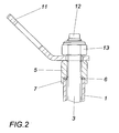
- the illustrated stop device comprises a useful as a dowel support tube 1 with a slotted Ein provisionde 2 and the support tube 1 with game passing through anchor bolt 3, which carries at its end of the Ein provisionde 2 of the support tube 1 end an expansion cone 4.
- the expansion cone 4 engages the anchor bolt 3, which is formed according to the embodiment as a threaded bolt, but may also have only a corresponding threaded portion, in an adjusting nut 5, which is axially supported on the end face of the Ein whode 2 support tube 1, and Although with the aid of a sliding ring 6.
- the arrangement is made such that the adjusting nut 5 the sliding ring 6 with a sleeve-like Approach 7 overlaps, which is guided on the support tube 1.
- the adjusting nut 5 is therefore kept centered with respect to the support tube 1 and can be rotated under favorable friction conditions for screw adjustment of the anchor bolt 3 because of the intermediate position of the sliding ring 6.
- the expansion cone 4 is retracted at the lower end of the anchor bolt 1 in the impact end 2 of the support tube, so that the slotted impact end 2 is expanded and applies pressure to the wall of a bore 8 in the support structure 9 of a roof.
- the impact end 2 is formed in an end portion 10 having a larger outer diameter. It follows, therefore, following this thickened end portion 10, a greater clearance between the support tube 1 and the bore wall, which facilitates the driving of the support tube 1 into the bore 8 of the support structure 9.
- the required anchoring of the support in the support structure 9 is ensured. It can therefore an attachment point 11, usually a stop lug, attached for personal protection equipment on the over the adjusting nut 5 projecting end portion 12 of the anchor bolt 3 and secured with a nut 13, it being important to ensure that the free rotation of the attachment point 11 observed remains.
- the co-rotation of the anchor bolt 3 when tightening the adjusting nut 5 by holding back to prevent for which the anchor bolt 3 can be provided at the projecting end portion 12 with flats for engaging a key.
Landscapes
- Engineering & Computer Science (AREA)
- Architecture (AREA)
- Mechanical Engineering (AREA)
- Civil Engineering (AREA)
- Structural Engineering (AREA)
- Joining Of Building Structures In Genera (AREA)
- Emergency Lowering Means (AREA)
Applications Claiming Priority (1)
| Application Number | Priority Date | Filing Date | Title |
|---|---|---|---|
| AT0032907U AT10009U1 (de) | 2007-05-22 | 2007-05-22 | Anschlagvorrichtung für eine absturzsicherung |
Publications (2)
| Publication Number | Publication Date |
|---|---|
| EP1995396A2 true EP1995396A2 (fr) | 2008-11-26 |
| EP1995396A3 EP1995396A3 (fr) | 2012-03-21 |
Family
ID=39367409
Family Applications (1)
| Application Number | Title | Priority Date | Filing Date |
|---|---|---|---|
| EP08450071A Withdrawn EP1995396A3 (fr) | 2007-05-22 | 2008-05-07 | Dispositif d'accrochage pour un équipement de protection contre les chutes |
Country Status (2)
| Country | Link |
|---|---|
| EP (1) | EP1995396A3 (fr) |
| AT (1) | AT10009U1 (fr) |
Cited By (2)
| Publication number | Priority date | Publication date | Assignee | Title |
|---|---|---|---|---|
| DE202013002968U1 (de) | 2013-03-27 | 2013-05-03 | Alstom Technology Ltd. | Anschlagvorrichtung zur Bereitstellung eines Anschlagpunkts |
| US20220226679A1 (en) * | 2020-10-28 | 2022-07-21 | Werner Co. | Expansion bolt and pivot and swivel mechanism therefor |
Families Citing this family (3)
| Publication number | Priority date | Publication date | Assignee | Title |
|---|---|---|---|---|
| DE102011078114A1 (de) | 2010-06-25 | 2012-04-19 | Em Tech-Power Gmbh | Absturzsicherung |
| AT510090B1 (de) * | 2010-06-25 | 2012-07-15 | Em Tech Power Gmbh | Absturzsicherung |
| DE102016109817A1 (de) * | 2016-05-27 | 2017-11-30 | Adolf Würth GmbH & Co. KG | Verspannen einer Spreizeinrichtung einer Anschlageinrichtung gegen Verankerungsuntergrund |
Citations (1)
| Publication number | Priority date | Publication date | Assignee | Title |
|---|---|---|---|---|
| EP1403446A2 (fr) | 2002-09-27 | 2004-03-31 | Klaus Fischer GmbH | Système de protection contre les chutes pour toitures plates ou à faible pente |
Family Cites Families (4)
| Publication number | Priority date | Publication date | Assignee | Title |
|---|---|---|---|---|
| DE7135049U (de) * | 1971-09-15 | 1972-02-03 | Schierling M | Sicherungsvorrichtung gegen absturz fuer arbeiten auf oder an daechern insbes. flachdaechern |
| EP0503677A3 (en) * | 1991-03-14 | 1993-01-13 | Maechtle Gmbh | Heavy duty anchor |
| EP1683931A2 (fr) * | 2005-01-21 | 2006-07-26 | Innotech Arbeitsschutz Gmbh | Dispositif de fixation pour un dispositif de protection contre les chutes |
| DE202005011463U1 (de) * | 2005-07-21 | 2005-09-29 | Beckers, Ludwig | Absturzsicherungsvorrichtung mit Stützrohr |
-
2007
- 2007-05-22 AT AT0032907U patent/AT10009U1/de not_active IP Right Cessation
-
2008
- 2008-05-07 EP EP08450071A patent/EP1995396A3/fr not_active Withdrawn
Patent Citations (1)
| Publication number | Priority date | Publication date | Assignee | Title |
|---|---|---|---|---|
| EP1403446A2 (fr) | 2002-09-27 | 2004-03-31 | Klaus Fischer GmbH | Système de protection contre les chutes pour toitures plates ou à faible pente |
Cited By (7)
| Publication number | Priority date | Publication date | Assignee | Title |
|---|---|---|---|---|
| DE202013002968U1 (de) | 2013-03-27 | 2013-05-03 | Alstom Technology Ltd. | Anschlagvorrichtung zur Bereitstellung eines Anschlagpunkts |
| US20220226679A1 (en) * | 2020-10-28 | 2022-07-21 | Werner Co. | Expansion bolt and pivot and swivel mechanism therefor |
| US11446526B2 (en) * | 2020-10-28 | 2022-09-20 | Werner Co. | Expansion bolt and pivot and swivel mechanism therefor |
| US11807499B2 (en) * | 2020-10-28 | 2023-11-07 | Werner Co. | Expansion bolt and pivot and swivel mechanism therefor |
| US12129880B2 (en) | 2020-10-28 | 2024-10-29 | Werner Co. | Expansion bolt and pivot and swivel mechanism therefor |
| US12129152B2 (en) | 2020-10-28 | 2024-10-29 | Werner Co. | Expansion bolt and pivot and swivel mechanism therefor |
| US20250012310A1 (en) * | 2020-10-28 | 2025-01-09 | Werner Co. | Expansion bolt and pivot and swivel mechanism therefor |
Also Published As
| Publication number | Publication date |
|---|---|
| EP1995396A3 (fr) | 2012-03-21 |
| AT10009U1 (de) | 2008-07-15 |
Similar Documents
| Publication | Publication Date | Title |
|---|---|---|
| EP1648627B1 (fr) | Dispositif pour poser et deposer une unite cylindre d'appui-palier | |
| EP1995396A2 (fr) | Dispositif d'accrochage pour un équipement de protection contre les chutes | |
| EP2464878A1 (fr) | Fixation de palier de laminoir | |
| DE9412105U1 (de) | Beschlag zur Festlegung einer Rinnenabdeckung | |
| DE102010064102B4 (de) | Lageranordnung und Walzeinheit für eine Walzwerkswalze | |
| DE3023411A1 (de) | Spreizanker | |
| DE2326713A1 (de) | Befestigungselement zur befestigung von bauteilen an einer wand oder dgl | |
| EP2010790A1 (fr) | Ancrage de fixation | |
| DE102010060394A1 (de) | Vorrichtung zur Befestigung eines sich von außen gegenüber dem Karosserieaußenblech einer Fahrzeugkarosserie abstützenden Anbauteils | |
| DE102006041211A1 (de) | Befestigungsvorrichtung für Profilrohre | |
| DE2513712A1 (de) | Unterflurhydrant | |
| DE10309792B4 (de) | Maschinenelement | |
| DE4034141C1 (en) | Guide for continuous steel casting - comprises supporting segments with rollers clamped by nuts and bolts to one-piece curved supporting frame | |
| DE2738522C3 (de) | Druckmittelbetriebener Arbeitszylinder | |
| DE202009007421U1 (de) | Vorrichtung zur vorgespannten Verankerung der Ankerschrauben von Masten, vorzugsweise von Signalmasten | |
| DE9410844U1 (de) | Dübel mit Ankerstange | |
| DE2155730C3 (de) | Tragschelle zum Befestigen einer Rohrleitung an einer Fläche, insbesonders am Boden oder an der Wand eines Behandlungsbehälters eines Zerstäubersystems | |
| WO2018162267A1 (fr) | Utilisation d'un élément d'ancrage à expansion pourvu d'une tête d'ancrage vissée | |
| DE3121819C1 (de) | Vorrichtung zum Verspannen von Profilsegmenten eines Ausbaurahmens | |
| DE4401478C2 (de) | Vorrichtung zum Festlegen von Bauteilen | |
| DE2511706C3 (de) | Gebirgsanker | |
| EP4170103A1 (fr) | Élément de fixation d'espacement, ensemble comprenant deux éléments de fixation d'espacement et élément de fixation d'espacement | |
| AT304631B (de) | Seilrolle od.dgl. | |
| DE2330538C3 (de) | Befestigungselement zur Verankerung in Bauwerksteilen | |
| EP0725196A1 (fr) | Etai téléscopique |
Legal Events
| Date | Code | Title | Description |
|---|---|---|---|
| PUAI | Public reference made under article 153(3) epc to a published international application that has entered the european phase |
Free format text: ORIGINAL CODE: 0009012 |
|
| AK | Designated contracting states |
Kind code of ref document: A2 Designated state(s): AT BE BG CH CY CZ DE DK EE ES FI FR GB GR HR HU IE IS IT LI LT LU LV MC MT NL NO PL PT RO SE SI SK TR |
|
| AX | Request for extension of the european patent |
Extension state: AL BA MK RS |
|
| PUAL | Search report despatched |
Free format text: ORIGINAL CODE: 0009013 |
|
| AK | Designated contracting states |
Kind code of ref document: A3 Designated state(s): AT BE BG CH CY CZ DE DK EE ES FI FR GB GR HR HU IE IS IT LI LT LU LV MC MT NL NO PL PT RO SE SI SK TR |
|
| AX | Request for extension of the european patent |
Extension state: AL BA MK RS |
|
| RIC1 | Information provided on ipc code assigned before grant |
Ipc: E04G 21/32 20060101AFI20120213BHEP |
|
| 17P | Request for examination filed |
Effective date: 20120905 |
|
| AKX | Designation fees paid |
Designated state(s): AT BE BG CH CY CZ DE DK EE ES FI FR GB GR HR HU IE IS IT LI LT LU LV MC MT NL NO PL PT RO SE SI SK TR |
|
| GRAP | Despatch of communication of intention to grant a patent |
Free format text: ORIGINAL CODE: EPIDOSNIGR1 |
|
| INTG | Intention to grant announced |
Effective date: 20150915 |
|
| STAA | Information on the status of an ep patent application or granted ep patent |
Free format text: STATUS: THE APPLICATION IS DEEMED TO BE WITHDRAWN |
|
| 18D | Application deemed to be withdrawn |
Effective date: 20160126 |