EP1995406A1 - Winkelpositionierungssensor für ein Bohrlochwerkzeug - Google Patents
Winkelpositionierungssensor für ein Bohrlochwerkzeug Download PDFInfo
- Publication number
- EP1995406A1 EP1995406A1 EP08251611A EP08251611A EP1995406A1 EP 1995406 A1 EP1995406 A1 EP 1995406A1 EP 08251611 A EP08251611 A EP 08251611A EP 08251611 A EP08251611 A EP 08251611A EP 1995406 A1 EP1995406 A1 EP 1995406A1
- Authority
- EP
- European Patent Office
- Prior art keywords
- magnetic
- magnets
- magnetic field
- sensors
- angular position
- Prior art date
- Legal status (The legal status is an assumption and is not a legal conclusion. Google has not performed a legal analysis and makes no representation as to the accuracy of the status listed.)
- Withdrawn
Links
Images



Classifications
-
- E—FIXED CONSTRUCTIONS
- E21—EARTH OR ROCK DRILLING; MINING
- E21B—EARTH OR ROCK DRILLING; OBTAINING OIL, GAS, WATER, SOLUBLE OR MELTABLE MATERIALS OR A SLURRY OF MINERALS FROM WELLS
- E21B47/00—Survey of boreholes or wells
- E21B47/02—Determining slope or direction
- E21B47/024—Determining slope or direction of devices in the borehole
Definitions
- the present invention relates generally to downhole tools, for example, including directional drilling tools having one or more steering blades. More particularly, embodiments of this invention relate to a sensor apparatus and a method for determining a relative angular position between various downhole tool components, such as a housing and a rotatable shaft.
- Measurement while drilling (MWD) and logging while drilling (LWD) tools are commonly used in oilfield drilling applications to measure physical properties of a subterranean borehole and the geological formations through which it penetrates.
- M/LWD techniques include, for example, natural gamma ray, spectral density, neutron density, inductive and galvanic resistivity, acoustic velocity, acoustic caliper, downhole pressure, and the like.
- Formations having recoverable hydrocarbons typically include certain well-known physical properties, for example, resistivity, porosity (density), and acoustic velocity values in a certain range.
- the azimuthal variation of particular formation and/or borehole properties i.e., the extent to which such properties vary about the circumference of the borehole.
- Such information may be utilized, for example, to locate faults and dips that may occur in the various layers that make up the strata.
- imaging measurements are utilized to make steering decisions for subsequent drilling of the borehole.
- information about the strata is generally required. As described above, such information may possibly be obtained from azimuthally sensitive measurements of the formation properties.
- Azimuthal imaging measurements typically make use of the rotation of the drill string (and therefore the LWD sensors) in the borehole during drilling.
- Conventional flux gate magnetometers are utilized to determine the magnetic toolface angle of the LWD sensor (which, as described in more detail below, is often referred to in the art as sensor azimuth) at the time a particular measurement or group of measurements are obtained by the sensor.
- conventional magnetometers have some characteristics that are not ideally suited to imaging applications. For example, flux gate magnetometers typically have a relatively limited bandwidth (e.g., about 5 Hz). Increasing the bandwidth requires increased power to increase the excitation frequency at which magnetic material is saturated and unsaturated. In LWD applications, electrical power is often supplied by batteries, making electrical power a somewhat scarce resource.
- One exemplary aspect of this invention includes a downhole tool having an angular position sensor disposed to measure the relative angular position between first and second members disposed to rotate about a common axis.
- a plurality of magnetic field sensors are deployed about the second member and disposed to measure magnetic flux emanating from first and second magnets deployed on the first member.
- a controller is programmed to determine the relative angular position based on magnetic measurements made by the magnetic field sensors.
- a downhole steering tool includes first and second magnets circumferentially spaced on the shaft and a plurality of magnetic field sensors deployed about the housing.
- Exemplary embodiments of the present invention may advantageously provide several technical advantages.
- sensor embodiments in accordance with the present invention are non-contact and therefore not typically subject to mechanical wear.
- embodiments of this invention tend to provide for accurate and reliable measurements with very little drift despite the high temperatures and pressures commonly encountered by downhole tools.
- embodiments of the invention are typically small, low mass, and low cost and tend to require minimal maintenance.
- angular position sensor embodiments in accordance with this invention may be used in the presence of high magnetic interference, e.g., in a steering tool or a mud motor deployed low in the BHA.
- Exemplary embodiments of the invention may be utilized to make high frequency angular position measurements and thus tend to be suitable for making high frequency toolface measurements for LWD imaging applications.
- Sensor embodiments in accordance with this invention may also be advantageously utilized to measure relative rotation rates between first and second downhole tool components.
- the present invention includes a downhole tool.
- the tool includes first and second members disposed to rotate about a common axis with respect to one another.
- First and second circumferentially spaced magnets are deployed on the first member and a plurality of circumferentially spaced magnetic field sensors are deployed on the second member such that at least one of the magnetic field sensors is in sensory range of magnetic flux emanating from at least one of the magnets.
- the tool further includes a controller disposed to calculate an angular position of the first member with respect to the second member from magnetic flux measurements at the magnetic field sensors.
- this invention includes a downhole tool.
- the tool includes a shaft deployed to rotate substantially freely in a housing.
- First and second arc-shaped magnets are circumferentially spaced on the shaft such that the first magnet has a magnetic north pole on an outer surface and a magnetic south pole an inner surface thereof and the second magnet has a magnetic south pole on an outer surface and a magnetic north pole on an inner surface thereof.
- a plurality of circumferentially spaced magnetic field sensors are deployed in the housing such that at least one of the magnetic field sensors is in sensory range of magnetic flux emanating from at least one of the magnets.
- the tool further includes a controller deployed in the housing and disposed to determine a relative angular position between the housing and the shaft from magnetic flux measurements made by the magnetic field sensors.
- the downhole tool comprises a steering tool including at least one blade disposed to extend radially outward from the housing into contact with a borehole wall.
- the first and second magnets are tapered, having a thin end and a thick end, such that a radial thickness of the magnets increases from the thin end to the thick end.
- the thick end has a thickness at least four times a thickness of the thin end.
- the thin end of the first magnet is proximate to the thin end of the second magnet.
- the first and second magnets each subtend a circular angle greater than an angular spacing between adjacent ones of the magnetic field sensors.
- the first and second magnets are configured to emit a magnetic field having a radial component that varies in strength substantially linearly with an angular position about the housing for a range of at least 30 degrees in angular position.
- the shaft and the housing are fabricated from at least one magnetic material.
- the tool comprises from about 5 to about 16 magnetic field sensors deployed equi-angularly about the circumference of the housing.
- the plurality of magnetic field sensors and the controller are deployed on a circumferential array, the array being deployed in a ring shaped, pressure resistant housing, the pressure resistant housing being deployed in the steering tool housing.
- this invention includes a method for determining a relative angular position between first and second members of a downhole tool.
- the method comprises: (a) deploying a downhole tool in a borehole, the downhole tool including first and second members disposed to rotate about a common axis with respect to one another, first and second circumferentially spaced magnets deployed on the first member and a plurality of circumferentially spaced magnetic field sensors are deployed on the second member; (b) causing each of the magnetic field sensors to measure a magnetic flux; and (c) processing the magnetic flux measurements to calculate the relative angular position between the first and second members.
- the first and second magnets are configured to emit a magnetic field having a radial component that varies in strength substantially linearly with an angular position about the second member for a range of at least 30 degrees in angular position.
- the first and second magnets comprise tapered, arc-shaped magnets, having a thin end and a thick end, such that a radial thickness of the magnets increases from the thin end to the thick end, the first magnet having a magnetic north pole on an outer surface thereof and a magnetic south pole an inner surface thereof, the second magnet having a magnetic south pole on an outer surface thereof and a magnetic north pole on an inner surface thereof.
- the method further comprises:
- the method further comprises:
- the invention relates to a method for steering the drilling direction of a subterranean borehole; the method comprising:
- (d) further comprises:
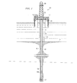
- FIGURE 1 depicts a drilling rig on which exemplary embodiments of the present invention may be deployed.
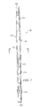
- FIGURE 2 is a perspective view of the steering tool shown on FIGURE 1 .
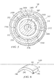
- FIGURE 3 depicts, in cross section, an exemplary angular sensor deployment in accordance with the present invention.
- FIGURE 4A depicts a plot of magnetic field strength versus angular position emanating from the magnets in the angular sensor deployment shown on FIGURE 3 .
- FIGURE 4B depicts a plot of exemplary magnetic field strength measurements made by each of the magnetic sensors in the angular sensor deployment shown on
- FIGURE 5 depicts, in cross section, another exemplary angular sensor deployment in accordance with the present invention.
- FIGURE 6 depicts a perspective view of an exemplary eyebrow magnet utilized -in the angular sensor deployment shown on FIGURE 5 .
- FIGURE 7A depicts a plot of magnetic field strength versus angular position emanating from the magnets in the angular sensor deployment shown on FIGURE 6 .
- FIGURE 7B depicts a plot of exemplary magnetic field strength measurements made by each of the magnetic sensors in the angular sensor deployment shown on FIGURE 6 .
- FIGURES 8A and 8B depict alternative magnet configurations suitable for use in the angular position sensor shown on FIGURE 5 .
- FIGURE 9A depicts, in cross section, still another exemplary angular sensor deployment in accordance with the present invention.
- FIGURE 9B depicts a plot of magnetic field strength versus angular position emanating from the magnets in the angular sensor deployment shown on FIGURE 9A .
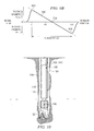
- FIGURE 10 depicts a bottom hole assembly suitable for use with directional (azimuthal) formation evaluation measurements in accordance with the present invention.
- azimuth has been used in the downhole drilling arts in two contexts, with a somewhat different meaning in each context.
- an azimuth angle is a horizontal angle from a fixed reference position.
- Mariners performing celestial navigation used the term, and it is this use that apparently forms the basis for the generally understood meaning of the term azimuth.
- a particular celestial object is selected and then a vertical circle, with the mariner at its center, is constructed such that the circle passes through the celestial object.
- the angular distance from a reference point (usually magnetic north) to the point at which the vertical circle intersects the horizon is the azimuth.
- the azimuth angle was usually measured in the clockwise direction.
- the reference plane is the horizontal plane tangent to the earth's surface at the point from which the celestial observation is made.
- the mariner's location forms the point of contact between the horizontal azimuthal reference plane and the surface of the earth.
- a borehole azimuth in the downhole drilling context is the relative bearing direction of the borehole at any particular point in a horizontal reference frame.
- a vertical circle may also be drawn in the downhole drilling context with the point of interest within the borehole being the center of the circle and the tangent to the borehole at the point of interest being the radius of the circle.
- the angular distance from the point at which this circle intersects the horizontal reference plane and the fixed reference point is referred to as the borehole azimuth.
- the borehole azimuth is typically measured in a clockwise direction.
- the borehole inclination is also used in this context to define a three-dimensional bearing direction of a point of interest within the borehole. Inclination is the angular separation between a tangent to the borehole at the point of interest and vertical.
- the azimuth and inclination values are typically used in drilling applications to identify bearing direction at various points along the length of the borehole.
- a set of discrete inclination and azimuth measurements along the length of the borehole is further commonly utilized to assemble a well survey (e.g., using the minimum curvature assumption). Such a survey describes the three-dimensional location of the borehole in a subterranean formation.
- azimuth is found in some borehole imaging art.
- the azimuthal reference plane is not necessarily horizontal (indeed, it seldom is).
- measurements of the property are taken at points around the circumference of the measurement tool.
- the azimuthal reference plane in this context is the plane centered at the measurement tool and perpendicular to the longitudinal direction of the borehole at that point. This plane, therefore, is fixed by the particular orientation of the borehole measurement tool at the time the relevant measurements are taken.
- An azimuth in this borehole imaging context is the angular separation in the azimuthal reference plane from a reference point to the measurement point.
- the azimuth is typically measured in the clockwise direction, and the reference point is frequently the high side of the borehole or measurement tool, relative to the earth's gravitational field, though magnetic north may be used as a reference direction in some situations.
- this context is different, and the meaning of azimuth here is somewhat different, this use is consistent with the traditional meaning and use of the term azimuth. If the longitudinal direction of the borehole at the measurement point is equated to the vertical direction in the traditional context, then the determination of an azimuth in the borehole imaging context is essentially the same as the traditional azimuthal determination.
- toolface angle Another important label used in the borehole imaging context is "toolface angle".
- face angle When a measurement tool is used to gather azimuthal imaging data, the point of the tool with the measuring sensor is identified as the “face” of the tool.
- the toolface angle therefore, is defined as the angular separation from a reference point to the radial direction of the toolface. The assumption here is that data gathered by the measuring sensor will be indicative of properties of the formation along a line or path that extends radially outward from the toolface into the formation.
- the toolface angle is an azimuth angle, where the measurement line or direction is defined for the position of the tool sensors.
- the oilfield services industry uses the term "gravitational toolface” when the toolface angle has a gravity reference (e.g., the high side of the borehole) and "magnetic toolface” when the toolface angle has a magnetic reference (e.g., magnetic north).
- a drilling direction may be defined, for example, via a borehole azimuth and an inclination (or borehole inclination).
- toolface and azimuth will be used interchangeably, though the toolface identifier will be used predominantly, to refer to an angular position about the circumference of a downhole tool (or about the circumference of the borehole).
- an LWD sensor for example, may be described as having an azimuth or a toolface.
- FIGURES 1 to 10 it will be understood that features or aspects of the embodiments illustrated may be shown from various views. Where such features or aspects are common to particular views, they are labeled using the same reference numeral. Thus, a feature or aspect labeled with a particular reference numeral on one view in FIGURES 1 to 10 may be described herein with respect to that reference numeral shown on other views.
- FIGURE 1 illustrates a drilling rig 10 suitable for utilizing exemplary downhole tool and method embodiments of the present invention.
- a semisubmersible drilling platform 12 is positioned over an oil or gas formation (not shown) disposed below the sea floor 16.
- a subsea conduit 18 extends from deck 20 of platform 12 to a wellhead installation 22.
- the platform may include a derrick 26 and a hoisting apparatus 28 for raising and lowering the drill string 30, which, as shown, extends into borehole 40 and includes a drill bit 32 and a directional drilling tool 100 (such as a three-dimensional rotary steerable tool).
- steering tool 100 includes one or more, usually three, blades 150 disposed to extend outward from the tool 100 and apply a lateral force and/or displacement to the borehole wall 42.
- the extension of the blades deflects the drill string 30 from the central axis of the borehole 40, thereby changing the drilling direction.
- Drill string 30 may further include a downhole drilling motor, a mud pulse telemetry system, and one or more additional sensors, such as LWD and/or MWD tools for sensing downhole characteristics of the borehole and the surrounding formation.
- additional sensors such as LWD and/or MWD tools for sensing downhole characteristics of the borehole and the surrounding formation. The invention is not limited in these regards.
- rotary steerable tool 100 is substantially cylindrical and includes threaded ends 102 and 104 (threads not shown) for connecting with other bottom hole assembly (BHA) components (e.g., connecting with the drill bit at end 104).
- BHA bottom hole assembly
- the rotary steerable tool 100 further includes a housing 110 deployed about a shaft (not shown on FIGURE 2 ).
- the shaft is typically configured to rotate relative to the housing 110.
- the housing 110 further includes at least one blade 150 deployed, for example, in a recess (not shown) therein.
- Directional drilling tool 100 further includes hydraulics 130 and electronics 140 modules (also referred to herein as control modules 130 and 140) deployed in the housing 110.
- the control modules 130 and 140 are configured for sensing and controlling the relative positions of the blades 150.
- electronic module also typically includes a tri-axial arrangement of accelerometers with one of the accelerometer having a known orientation relative to the longitudinal axis of the tool 100.
- one or more of blades 150 are extended and exert a force against the borehole wall.
- the rotary steerable tool 100 is moved away from the center of the borehole by this operation, thereby altering the drilling path.
- increasing the offset i.e., increasing the distance between the tool axis and the borehole axis via extending one or more of the blades
- the tool 100 may also be moved back towards the borehole axis if it is already eccentered. It will be understood that the drilling direction (whether straight or curved) is determined by the positions of the blades with respect to housing 110 as well as by the angular position (i.e., the azimuth) of the housing 110 in the borehole.
- Angular sensor 200 is disposed to measure the relative angular position between shaft 115 and housing 110 and may be deployed, for example, in control module 140 ( FIGURE 2 ).
- angular sensor 200 includes first and second magnets 220A and 220B deployed on the shaft 115 and a plurality of magnetic field sensors 210AH deployed about the circumference of the housing 110.
- the invention is not limited in this regard, however, as the magnets 220A and 220B may be deployed on the housing 110 and magnetic field sensors 210A-H on the shaft 115.
- Magnets 220A and 220B are angularly offset about the circumference of the shaft 115 by an angle ⁇ .
- magnets 220A and 220B are angularly offset by an angle of 90 degrees; however, the invention is not limited in this regard.
- Magnets 220A and 220B may be angularly offset by substantially any suitable angle. Angles in the range from about 30 to about 180 degrees are generally advantageous.
- Magnets 220A and 220B also typically have substantially equal magnetic pole strengths and opposite polarity, although the invention is expressly not limited in this regard.
- magnet 220A includes an approximately cylindrical magnet having a magnetic north pole facing radially outward from the tool axis while magnetic 220B includes an approximately cylindrical magnet having a magnetic south pole facing radially outward towards the tool axis.
- magnets 220A and 220B may each include first and second magnets having opposing magnetic poles facing one another such that magnetic flux emanates radially outward from the tool axis (or inward towards the tool axis depending upon the polarity of the magnets).
- magnet 220A may include north-north opposing poles, for example, while magnet 220B may include south-south opposing poles.
- magnetic field sensors 210A-H are deployed about the circumference of the tool 100 such that at least two of the sensors 210A-H are within sensory range of magnetic flux emanating from the magnets 220A and 220B.
- at least sensors 210A and 210C are in sensory range of the magnetic flux.
- Magnetic field sensors 210A-H may include substantially any type of magnetic sensor, e.g., including magnetometers, reed switches, magnetoresistive sensors, and/or Hall-Effect sensors, however magnetoresistive sensors and Hall-Effect sensors are generally preferred.
- each sensor may have either a ratiometric (analog) or digital output.
- FIGURE 3 shows eight magnetic field sensors 210A-H, it will be appreciated by those of ordinary skill on the art that this invention may equivalently utilize substantially any suitable plurality of magnetic field sensors. Typically from about four to about sixteen sensors are preferred. Too few sensors tend to result in a degradation of angular sensitivity (although degraded angular sensitivity may be acceptable, for example, in certain LWD imaging applications in which the LWD sensor has poor angular sensitivity). The use of sixteen or more sensors, while providing excellent angular sensitivity, increases wiring and power requirements while also tending to negatively impact system reliability.
- each magnetic field sensor 210A-H is deployed so that its axis of sensitivity is substantially radially aligned (i.e., pointing towards the center of the shaft 115), although the invention is not limited in this regard. It will be appreciated by those of ordinary skill in the art that a magnetic sensor is typically sensitive only to the component of the magnetic flux that is aligned (parallel) with the sensor's axis of sensitivity. It will also be appreciated that the exemplary embodiment shown on FIGURE 3 results in magnetic flux lines that are substantially radially aligned adjacent magnets 220A and 220B.
- the magnetic sensor 210AH located closest to magnet 220A tends to sense the highest positive magnetic flux (magnetic flux directed outward for the tool axis) and the sensor closest to magnet 220B tends to sense the highest negative magnetic flux (magnetic flux directed inward towards the tool axis).
- magnetic sensor 210A tends to measure the highest positive magnetic flux while sensor 210C tends to measure the highest negative magnetic flux.
- the invention is not limited by the exemplary sensor orientation depicted on FIGURE 3 .
- the radial flux includes positive 510 and negative 520 maxima.
- the positive maximum 510 is located radially outward from magnet 220A (i.e., at about 15 degrees in the exemplary embodiment shown).
- the negative maximum 520 is located radially outward from magnet 220B (i.e., at about 105 degrees in the exemplary embodiment shown).
- a magnetic flux null 530 (also referred to as a zero-crossing) is located between the positive 510 and negative 520 maxima (i.e., at about 60 degrees in the exemplary embodiment shown).
- the radial flux depicted in FIGURE 4A is for an exemplary embodiment in which the shaft 115 and housing 110 are fabricated from a non-magnetic steel.
- the positive and negative maxima 510 and 520 typically become more sharply defined with respect to angular position.
- the relative rotational position of the magnets 220A and 220B (and therefore the shaft) with respect to the magnetic sensors 210A-H (and therefore the housing 110) may be determined by locating the positive and/or negative maxima 510 and 520 or the zero-crossing 530.
- Data points 450 represent the magnetic field strength as measured by each of sensors 210A-H on FIGURE 3 .
- the angular position half way between magnets 220A and 220B is indicated by zero-crossing 430, the location on the circumferential array of magnetic field sensors at which the magnetic flux is substantially null and at which the polarity of the magnetic field changes from positive to negative (or negative to positive).
- zero-crossing 430 is at an angular position of about 60 degrees (as described above with respect to FIGURE 3 ).
- a processor (such as processor 255) first selects adjacent sensors (e.g., sensors 210B and 210C) between which the sign of the magnetic field changes (from positive to negative or negative to positive).
- the position of the zero crossing 430 may then be determined, for example, by fitting a straight line 470 through the data points on either side of the zero crossing (e.g., between the measurements made by sensors 210B and 210C in the embodiment shown on FIGURE 4B ).
- P represents the angular position of the zero crossing
- L represents the angular distance interval between adjacent sensors in degrees (e.g., 45 degrees in the exemplary embodiment shown on FIGURES 3 and 5 )
- a and B represent the absolute values of the magnetic field measured on either side of the zero crossing ( A and B are shown on FIGURES 4B and 7B )
- x 2 (sensor 210B).
- the magnet arrangement shown on FIGURE 3 (including magnets 220A and 220B) tends to result angular position values having small, systematic errors at certain angular positions due to the non-linearly of the magnetic flux profile as a function of angular position. This error is readily corrected, when necessary, using known calibration methods (e.g., look-up tables or polynomial fitting). It will also be appreciated that the magnet arrangement shown on FIGURE 3 advantageously makes use of inexpensive and readily available off-the-shelf magnets (e.g., square, rectangular or cylindrical magnets).
- FIGURE 5 an alternative embodiment of an angular sensor 200' in accordance with the present invention is depicted in cross section.
- Angular sensor 200' is also disposed to measure the relative angular position between shaft 115 and housing 110 and may be deployed, for example, in control module 140 ( FIGURE 2 ).
- Sensor 200' is substantially identical to sensor 200 with the exception that it includes first and second tapered, arc-shaped magnets 240A and 240B (also referred to herein as eyebrow magnets) deployed on the shaft 115.
- first and second tapered, arc-shaped magnets 240A and 240B also referred to herein as eyebrow magnets
- One exemplary embodiment of eyebrow magnet 240A is also shown on FIGURE 6 .
- Eyebrow magnets 240A and 240B include inner and outer faces 242 and 244, with the outer face 244 having a radius of curvature approximately equal to that of the outer surface of the shaft 115. Eyebrow magnets 240A and 240B also include relatively thick 246 and relatively thin 248 ends. While the invention is not limited in this regard, the thickness of end 246 is at least four times greater than that of end 248 in one exemplary embodiment.
- magnets 240A and 240B are substantially identical in shape and have substantially equal and opposite magnetic pole strengths.
- Magnet 240A includes a magnetic north pole on its outer face 244 and a magnetic south pole on its inner face 242 ( FIGURE 6 ).
- Magnet 240B has the opposite polarity with a magnetic south pole on its outer face 244 and a magnetic north pole on its inner face 242.
- Magnets 240A and 240B are typically deployed adjacent to one another about the shaft 115 such that their thin ends 248 are in contact (or near contact) with one another.
- FIGURE 5 shows an exemplary embodiment in which the magnets 240A and 240B are deployed in a tapered recess in the outer surface of the shaft
- magnets 240A and 240B may be equivalently deployed on the outer surface of the shaft 115.
- the invention is not limited in these regards.
- magnets 240A and 240B each span a circular arc of about 55 degrees about the circumference of the shaft.
- magnets 240A and 240B in combination span a circular arc ⁇ ' of about 110 degrees.
- the invention is also not limited in these regards (as described in more detail below).
- the radial flux includes positive 710 and negative 720 maxima.
- the positive maximum 710 is located radially outward from and near the thick end 246 of magnet 240A (i.e., at an angle of about 5-10 degrees in the exemplary embodiment shown).
- the negative maximum 720 is located radially outward from and near the thick end of magnet 240B (i.e., at about 100-105 degrees in the exemplary embodiment shown).
- a magnetic flux null 730 (also referred to as a zero-crossing) is located between the positive 710 and negative 720 maxima (i.e., at about 55 degrees in the exemplary embodiment shown). Moreover, as shown at 740, the radial flux is advantageously substantially linear with angular position between the maxima 710 and 720, which typically eliminates the need for correction algorithms. As described above with respect to angular sensor 200, the relative rotational position of the magnets 240A and 240B (and therefore the shaft) with respect to the magnetic sensors 210A-H (and therefore the housing 110) may be determined from the positive and/or negative maxima 710 and 720 or the zero-crossing 730.
- eyebrow magnets 240A and 240B may be advantageously sized and shaped to generate a magnetic flux that varies linearly 740 with angular position between the positive and negative maxima 710 and 720.
- this linear region 740 spans approximately 95 degrees in angular position.
- the invention is not limited in this regard, however, as the angular expanse of the linear region 740 may be increased by increasing the arc-length of magnets 240A and 240B and decreased by decreasing the arc-length of magnets 240A and 240B.
- substantially linear region 740 it is desirable for substantially linear region 740 to have an angular expanse of at least twice the angular interval between adjacent ones of magnetic sensors 210A-H. In this way at least two of the magnetic sensors 210A-H are located in the linear region 740 at all relative angular positions.
- embodiments of the invention utilizing fewer magnetic field sensors desirably utilize eyebrow magnets having a longer arc-length (e.g., about 90 degrees each for an embodiment including five magnetic field sensors).
- embodiments of the invention utilizing more magnetic field sensors may optionally utilize eyebrow magnets having a shorter arc-length (e.g., about 30 degrees each for an embodiment including 16 magnetic field sensors).
- Eyebrow magnets 240A and 240B are also advantageously sized and shaped to generate the above described magnetic flux profile (as a function of angular position) for tool embodiments in which both the shaft 115 and the housing 110 are fabricated from a magnetic material such as 4145 low alloy steel. It will be readily understood by those of ordinary skill in the art that the use of magnetic steel is advantageous in that it tends to significantly reduce manufacturing costs (due to the increased availability and reduced cost of the steel itself) and also tends to increase overall tool strength. Notwithstanding, magnets 240A and 240B may also be sized and shaped to generate the above described magnetic profile for tool embodiments in which either one or both of the shaft 115 and the housing 110 are fabricated from nonmagnetic steel.
- FIGURE 7B a graphical representation of one exemplary mathematical technique for determining the angular position is illustrated.
- the technique illustrated in FIGURE 7B is similar to that described above with respect to FIGURE 4B .
- Data points 750 represent the magnetic field strength values measured by sensors 210A-H on FIGURE 5 .
- the angular position of the contact point 245 between magnets 240A and 240B is indicated by zero-crossing 730, which as described above is the location on the circumferential array of magnetic field sensors 210A-H at which the magnetic flux is substantially null and at which the polarity of the magnetic field changes from positive to negative (or negative to positive).
- zero-crossing 730 is at an angular position of about 55 degrees (as described above with respect to FIGURES 5 and 7A ). Note that the position of the zero crossing 730 (and therefore the angular position of contact point 245) is located between sensors 210B and 210C.
- a processor may first select adjacent sensors (e.g., sensors 210B and 210C) between which the sign of the magnetic field changes (from positive to negative or negative to positive). The position of the zero crossing 730 may then be determined, for example, by fitting a straight line 770 through the data points on either side of the zero crossing (e.g., between the measurements made by sensors 210B and 210C in the embodiment shown on FIGURE 7B ). The location of the zero crossing 730 may then be determined mathematically from the magnetic field measurements, for example, via Equation 1 as described above.
- substantially any other suitable magnet configurations may be utilized to achieve a magnetic profile having a linear region similar to that described above with respect to FIGURE 7A .
- arc shaped magnets having a constant thickness, but a "tapered magnetization" such that the magnetic strength of each magnet increases from one end to another may be suitable substitutes for magnets 240A and 240B shown on FIGURE 5 .
- eyebrow magnets 240A and 240B FIGURE 5
- sets 340A and 340B of discrete magnets have been replaced with sets 340A and 340B of discrete magnets.
- Set 340A includes a plurality of discrete magnets in which magnet 341 A is thicker than magnet 342A, which is thicker than magnet 343A and so on for magnets 344A and 345A.
- set 340B includes a plurality of discrete magnets in which magnet 341 B is thicker than magnet 342B, which is thicker than magnet 343B and so on for magnets 344B and 345B.
- each of the magnets in sets 340A and 340B may have substantially the same thickness, but have a decreasing magnetic field strength from magnet 341 A to 345A and from magnet 341 B to 345B. It will be understood by those of ordinary skill that increasing the number of magnets in sets 340A and 340B tends to result in a magnetic flux profile more closely approximating that shown on FIGURE 7A .
- eyebrow magnets 240A and 240B have been replaced by arc-shaped magnets 240A' and 240B'.
- the exemplary embodiment shown further includes tapered, arc-shaped magnetic lenses 245A and 245B deployed about the corresponding magnets 240A' and 240B' (i.e., radially between the magnets and the magnetic field sensors 210A-H).
- Magnetic lenses 245A and 245B are fabricated from a magnetic material (magnetically permeable material), such as 4145 low alloy steel, and serve to focus magnetic flux emanating from magnets 240A' and 240B' such that the magnetic flux profile about the shaft approximates that described above with respect to FIGURE 7A .
- the exemplary angular position sensor embodiments shown on FIGURES 3 and 5 include magnetic sensors 210A-H deployed at equal angular intervals about the circumference of housing 110. It will be appreciated that the invention is not limited in this regard. Magnetic sensors 210A-H may alternatively be deployed at unequal intervals. For example, more sensors may be deployed on a one side of the housing 110 than on an opposing side to provide better angular sensitivity on that side of the tool. Nor is the invention limited to embodiments capable of measuring an angular position about the full circumference of the tool. Thus, certain embodiments may include magnetic sensors about only a portion of the housing circumference. Measurements about only a portion of the circumference may be advantageous, for example, in measuring the angular position of a hinged object.
- angular position sensors 200 and 200' are not limited to embodiments in which the magnets are deployed on the shaft 115 and the magnetic sensors 210A-H in the housing.
- the magnets may be equivalently deployed in the housing 110 and the magnetic sensors 210A-H on the shaft.
- Angular position sensor 300 is configured to measure the angular position between housing 390 and shaft 380 about a portion of the circumference (from about 0 to about 270 degrees in the exemplary embodiment shown).
- Angular position sensor 300 includes first and second eyebrow magnets 320A and 320B and only a single magnetic field sensor 310.
- the radial flux about the circumference of shaft 380 is plotted on FIGURE 9B . As shown at 940, the radial flux is advantageously substantially linear with angular position between maxima 910 and 920.
- P the angular position
- m the slope of linear region 940 (e.g., in degrees per Gauss)
- F represents the magnetic flux density measured at magnetic field sensor 310
- b represents the angular position of zero crossing 930 (135 degrees in the exemplary embodiment shown).
- angular position sensing methods described above with respect to FIGURES 3 through 7B and Equation 1 advantageously require minimal computational resources (minimal processing power), which is critical in downhole applications in which 8-bit microprocessors are commonly used. These methods also provide accurate angular position determination about substantially the entire circumference of the tool.
- the zero-crossing method tends to be further advantageous in that a wider sensor input range is available (from the negative to positive saturation limits of the sensors).
- downhole tools must typically be designed to withstand shock levels in the range of 1000G on each axis and vibration levels of 50G root mean square. Moreover, downhole tools are also typically subject to pressures ranging up to about 25,000 psi and temperatures ranging up to about 200 degrees C.
- magnetic field sensors 210A-H are shown deployed in a pressure resistant housing 205. Such an arrangement is preferred for downhole applications utilizing solid state magnetic field sensors such as Hall-Effect sensors and magnetoresistive sensors.
- pressure housing 205 includes a sealed ring that is configured to resist downhole pressures which can damage sensitive electronic components.
- the pressure housing 205 is also configured to accommodate the magnetic field sensors 210A-H and other optional electronics, such as processor 255.
- Advantageous embodiments of the pressure housing 205 are fabricated from nonmagnetic material, such as P550 (austenitic manganese chromium steel).
- magnetic field sensors 210A-H are deployed on a circumferential circuit board array 250, which is fabricated, for example from a flexible, temperature resistant material, such as PEEK (polyetheretherketone).
- the circumferential array 250, including the magnetic field sensors 210A-H and processor 255, is also typically encapsulated in a potting material to improve resistance to shocks and vibrations.
- the magnets utilized in this invention are also typically selected in view of demanding downhole conditions.
- suitable magnets must posses a sufficiently high Curie temperature to prevent demagnetization at downhole temperatures.
- Samarium cobalt (SaCo 5 ) magnets are typically preferred in view of their high Curie Temperatures (e.g., from about 700 to 800 degrees C).
- the magnets may also be deployed in a shock resistant housing, for example, including a non-magnetic sleeve deployed about the magnets and shaft 115.
- the output of each magnetic sensor may be advantageously electronically coupled to the input of a local microprocessor.
- the microprocessor serves to process the data received by the magnetic sensors (e.g., according to Equation 1 as described above).
- the microprocessor (such as processor 255) is embedded with the magnetic field sensors 210A-H in the circumferential array 250, for example, as shown on FIGURES 3 and 5 and therefore located close to the magnetic sensors.
- the microprocessor output (rather than the signals from the individual magnetic sensors) is typically electronically coupled with a main processor which is deployed further away from the magnetic field sensors (e.g., deployed in control module 140 as shown on FIGURE 2 ).
- This configuration advantageously reduces wiring and feed-through requirements in the body of the downhole tool, which is particularly important in smaller diameter tool embodiments (e.g., tools having a diameter of less than about 12 inches).
- Digital output from the embedded microprocessor also tends to advantageously reduce electrical interference in wiring to the main processor.
- Embedded microprocessor output may also be combined with a voltage source line to further reduce the number of wires required, e.g., one wire for combined power and data output and one wire for ground (or alternatively, the use of a chassis ground). This may be accomplished, for example, by imparting a high frequency digital signal to the voltage source line or by modulating the current draw from the voltage source line. Such techniques are known to those of ordinary skill in the art.
- microprocessor 255 includes processor-readable or computer-readable program code embodying logic, including instructions for calculating a precise angular position of the shaft 115 relative to the housing 110 from the received magnetic sensor measurements. While substantially any logic routines may be utilized, it will be appreciated that logic routines requiring minimal processing power (e.g., as described above with respect to Equation 1) are advantageous for downhole applications (particularly for small-diameter LWD, MWD, and directional drilling embodiments of the invention in which both electrical and electronic processing power are often severely limited).
- angular position sensors in accordance with this invention may be deployed in conventional and/or steerable drilling fluid (mud) motors and utilized to determine the angular position of drill string components (e.g., MWD or LWD sensors) deployed below the motor with respect to those deployed above the motor.
- the angular position sensor may be disposed, for example, to measure the relative angular position between the rotor and stator in the mud motor.
- the angular position measurements described above may be advantageously utilized in combination with a formation evaluation sensor (an MWD/LWD sensor) to make near-bit, azimuthally sensitive formation evaluation measurements. Such measurements may in turn be used to form borehole images using known LWD imaging techniques.
- a formation evaluation sensor an MWD/LWD sensor
- Such measurements may in turn be used to form borehole images using known LWD imaging techniques.
- FIGURE 10 one exemplary embodiment of a BHA suitable for making direction formation evaluation (FE) measurements in accordance with exemplary embodiments of the present invention is illustrated.
- the BHA includes a drill bit assembly 32 coupled with a steering tool 100.
- Steering tool 100 includes a tri-axial accelerometer set 180 deployed in housing 110 and an angular sensor 200, 200' disposed to measure the angular position between rotating shaft 115 and housing 110.
- steering tool 100 further includes one or more formation evaluation sensors 190 deployed near the drill bit 120 (e.g., in a near-bit stabilizer or other near-bit sub).
- Formation evaluation sensor 190 may include substantially any downhole LWD or MWD sensor(s) for measuring borehole and/or formation properties, for example, including a natural gamma ray sensor, a neutron sensor, a density sensor, a resistivity sensor, a formation pressure sensor, an annular pressure sensor, an ultrasonic sensor, an audio-frequency acoustic sensor, a borehole caliper sensor (with or without physical contact), and the like.
- the invention is not limited in these regards.
- formation evaluation sensor(s) 190 are rotationally coupled with the drill string and typically rotate about the borehole during drilling. Accelerometer set 180 and angular position sensor 200, 200' may be used in combination to determine the tool face (azimuthal position) of the formation evaluation sensor(s) during drilling.
- the angular position of the shaft 115 in the housing typically varies in time (due to the rotation of the shaft in the substantially non-rotating housing 110). At substantially any instant in time, a directional formation evaluation measurement may be made.
- the angular position of the shaft with respect to the housing may be measured using angular position sensor 200, 200', for example as described above with respect to FIGURES 3-7B , and the tool face of the housing 110 may be determined via accelerometer measurements as is known to those of ordinary skill in the art.
- the toolface of the formation evaluation sensor(s) 190 may then be determined, for example, via subtracting (or adding) the angular position measurement from the toolface of the housing 110.
- the toolface of the housing 110 may be computed substantially any known surveying sensor arrangement, e.g., including accelerometers, magnetometers, and gyros, however, accelerometer deployments are typically preferred low in the BHA.
- the toolface measurement sensors are not limited to tri-axial arrangements.
- the above described toolface measurements may be utilized in geo-steering applications and/or to form borehole images using techniques known to those of skill in the art.
- angular position measurements may be advantageously obtained, for example, at approximately 10 millisecond intervals.
- toolface angles may be determined 50 times per revolution (i.e., at approximately 7 degree intervals assuming a uniform rotation rate).
- angular position measurements may be made at substantially any suitable time interval.
- Hall-Effect sensors are known to be capable of achieving high frequency magnetic field measurements and are easily capable of obtaining magnetic field measurements at intervals of less than 10 milliseconds.
- the invention is also not limited to steering tool or rotary steerable embodiments. Rather, directional formation evaluation measurements may be made using substantially any suitable BHA configuration in which one portion of the BHA rotates about a longitudinal axis with respect to another portion of the BHA.
- a near-bit formation evaluation sensor may be deployed between a drill bit and conventional and/or steerable mud motor or alternatively in the bit. Angular position measurements and accelerometer measurements may then be utilized, as described above, to calculate the toolface of the formation evaluation sensor.
- Exemplary angular position sensor embodiments in accordance with this invention may also be advantageously utilized to make average and differential relative rotation rate measurements, for example, between shaft 115 and housing 110 ( FIGURES 3 and 5 ).
- Equation 2 may be advantageously utilized to determine rotation rates in either rotational direction (either clockwise or counterclockwise). Equation 2 may also be utilized to determine both instantaneous (differential) and average rotation rates. To determine an instantaneous rotation rate, time interval ⁇ t is typically less than 1 second (e.g., 10 milliseconds as described above). To determine an average rotation rates, time interval ⁇ t is typically greater than 1 second.
- measurement of the relative rotation rate between the shaft and the housing may be advantageously utilized.
- average rotation rate measurements may be utilized in decoding transmitted tool commands as is disclosed in commonly-assigned, co-pending U.S. Patent Application Serial Nos. 10/882,789 ( U.S. Patent Application Publication No. 2005/0001737 ) and 11/062,299 ( U.S. Patent Application Publication No. 2006/0185900 ).
- Instantaneous (differential) rotation rate measurements may be further utilized to detect and quantify torsional vibration (stick-slip) of the drill string during drilling as is disclosed in commonly-assigned, co-pending U.S. Patent Application Serial No. 11/454,019 .
- Angular position sensors 200, 200' may also be advantageously utilized to control a steering tool (i.e., to control the direction of drilling of a subterranean borehole).
- a BHA may include a measurement while drilling tool having a magnetic surveying device (such as a magnetometer) coupled with the drill string and deployed above a steering tool (both of which are deployed above a drill bit).
- the magnetic surveying device may be utilized to measure magnetic tool face angles of the drill string.
- a high frequency magnetic surveying device such as disclosed in co-pending, commonly assigned U.S. Patent Application Publication No. 2007/0030007 may likewise be utilized to determine the magnetic tool face of the drill string.
- the angular position sensor 200, 200' may be simultaneously utilized to measure the corresponding angular position of the steering tool housing with respect to the drill string as described above.
- the combination of the magnetic tool face measurements of the drill string and the angular position measurements may be utilized (as described above) to calculate the magnetic toolface of the housing (e.g., by subtracting the angular position from the measured toolface).
- a magnetic tool face of the housing may then be utilized to control the drilling course of a directional drilling device (such as a rotary steerable tool) as is known to those of ordinary skill in the drilling arts.
- a directional drilling device such as a rotary steerable tool
- Such a control method may be particularly advantageous for small diameter tools since it obviates the need to have a dedicated tool face sensor in the steering tool housing.
- the above described steering control method may also be advantageously utilized when kicking off from a vertical section of a borehole.
- a gravity toolface in a vertical section using conventional sensor arrangements.
- magnetic toolface measurements are typically unreliable near steering tools or mud motors due to magnetic interference from magnetized tool components.
- the kickoff direction is often selected randomly and the well path corrected to plan after drilling about a 50-100 foot section of build. While this approach is serviceable, it also wastes valuable rig time and results a borehole having undesirable tortuosity.
- an angular position sensor in accordance with this invention advantageously enables a borehole to be kicked off from vertical in the proper direction.
- the angular position between housing 110 and shaft 115 may be measured as described above.
- a magnetic toolface may also be measured at an MWD tool, which is typically rotationally coupled with the drill string and deployed above the steering tool 100. Therefore, a magnetic toolface of the housing 110 may be calculated from the angular position and magnetic toolface measurements (e.g., by subtracting the measured angular position from the measured magnetic toolface).
- the borehole may then be kicked off at the appropriate direction with respect to magnetic north (i.e., at the predetermined borehole azimuth).
- steering tool control methods described herein are not limited to the exemplary angular position sensor embodiments described above. It will be understood that such steering tool control methods may be utilized with substantially any steering tool configuration employing any suitable angular position sensor.
Landscapes
- Physics & Mathematics (AREA)
- Life Sciences & Earth Sciences (AREA)
- Engineering & Computer Science (AREA)
- Geology (AREA)
- Mining & Mineral Resources (AREA)
- Geophysics (AREA)
- Environmental & Geological Engineering (AREA)
- Fluid Mechanics (AREA)
- General Life Sciences & Earth Sciences (AREA)
- Geochemistry & Mineralogy (AREA)
- Measurement Of Length, Angles, Or The Like Using Electric Or Magnetic Means (AREA)
Applications Claiming Priority (1)
| Application Number | Priority Date | Filing Date | Title |
|---|---|---|---|
| US11/805,230 US8497685B2 (en) | 2007-05-22 | 2007-05-22 | Angular position sensor for a downhole tool |
Publications (1)
| Publication Number | Publication Date |
|---|---|
| EP1995406A1 true EP1995406A1 (de) | 2008-11-26 |
Family
ID=39673252
Family Applications (1)
| Application Number | Title | Priority Date | Filing Date |
|---|---|---|---|
| EP08251611A Withdrawn EP1995406A1 (de) | 2007-05-22 | 2008-05-02 | Winkelpositionierungssensor für ein Bohrlochwerkzeug |
Country Status (2)
| Country | Link |
|---|---|
| US (1) | US8497685B2 (de) |
| EP (1) | EP1995406A1 (de) |
Cited By (6)
| Publication number | Priority date | Publication date | Assignee | Title |
|---|---|---|---|---|
| GB2467077B (en) * | 2007-11-16 | 2012-06-27 | Baker Hughes Inc | Position sensor for a downhole completion device |
| WO2015195089A1 (en) * | 2014-06-17 | 2015-12-23 | Halliburton Energy Services, Inc. | Reluctance sensor for measuring a magnetizable structure in a subterranean environment |
| US9933544B2 (en) | 2014-12-24 | 2018-04-03 | Halliburton Energy Services, Inc. | Near-bit gamma ray sensors in a rotating section of a rotary steerable system |
| CN108612520A (zh) * | 2018-05-09 | 2018-10-02 | 中国地质大学(武汉) | 一种基于光纤原理的工具面角传感器 |
| US20210355812A1 (en) * | 2020-05-12 | 2021-11-18 | Halliburton Energy Services, Inc. | Mud angle determination for electromagnetic imager tools |
| EP4407141A1 (de) * | 2023-01-25 | 2024-07-31 | TRACTO-TECHNIK GmbH & Co. KG | Gestängeschusssystem |
Families Citing this family (39)
| Publication number | Priority date | Publication date | Assignee | Title |
|---|---|---|---|---|
| US20080236819A1 (en) * | 2007-03-28 | 2008-10-02 | Weatherford/Lamb, Inc. | Position sensor for determining operational condition of downhole tool |
| EP2265911A2 (de) * | 2008-04-15 | 2010-12-29 | Alstom Technology Ltd | Verfahren zur überwachung einer elektrodynamischen maschine |
| KR100986703B1 (ko) * | 2008-08-05 | 2010-10-11 | 이근호 | 지반 침하 측정 시스템 |
| US20100101860A1 (en) * | 2008-10-29 | 2010-04-29 | Baker Hughes Incorporated | Phase Estimation From Rotating Sensors To Get a Toolface |
| US9062497B2 (en) * | 2008-10-29 | 2015-06-23 | Baker Hughes Incorporated | Phase estimation from rotating sensors to get a toolface |
| CA2763285C (en) * | 2009-05-22 | 2018-01-09 | Schlumberger Canada Limited | Optimization of neutron-gamma tools for inelastic gamma-ray logging |
| US9702241B2 (en) | 2009-08-05 | 2017-07-11 | Halliburton Energy Services, Inc. | Azimuthal orientation determination |
| US9366131B2 (en) * | 2009-12-22 | 2016-06-14 | Precision Energy Services, Inc. | Analyzing toolface velocity to detect detrimental vibration during drilling |
| US8521469B2 (en) * | 2010-07-21 | 2013-08-27 | General Electric Company | System and method for determining an orientation of a device |
| EP2596386A4 (de) * | 2010-08-26 | 2017-09-13 | Smith International, Inc. | Verfahren zur messung der dichte einer unterirdischen formation mit einem neutronengenerator |
| US9638020B2 (en) * | 2011-02-17 | 2017-05-02 | Halliburton Energy Services, Inc. | System and method for kicking-off a rotary steerable |
| BR112014009085A2 (pt) | 2011-10-14 | 2017-05-09 | Precision Energy Services Inc | análise de dinâmica de coluna de perfuração usando um sensor de taxa angular |
| US8878522B2 (en) * | 2011-12-20 | 2014-11-04 | Gm Global Technology Operations, Llc | Magnetic linear position sensor |
| CN103376052B (zh) * | 2012-04-16 | 2016-12-21 | 泰科电子(上海)有限公司 | 磁铁装置和位置感测系统 |
| AU2012384528B2 (en) * | 2012-07-02 | 2015-10-08 | Halliburton Energy Services, Inc. | Angular position sensor with magnetometer |
| US9605527B2 (en) * | 2012-12-05 | 2017-03-28 | Baker Hughes Incorporated | Reducing rotational vibration in rotational measurements |
| US9638819B2 (en) * | 2013-06-18 | 2017-05-02 | Well Resolutions Technology | Modular resistivity sensor for downhole measurement while drilling |
| CA2913964A1 (en) * | 2013-07-11 | 2015-01-15 | Halliburton Energy Services, Inc. | Rotationally-independent wellbore ranging |
| US9567844B2 (en) | 2013-10-10 | 2017-02-14 | Weatherford Technology Holdings, Llc | Analysis of drillstring dynamics using angular and linear motion data from multiple accelerometer pairs |
| US9822633B2 (en) | 2013-10-22 | 2017-11-21 | Schlumberger Technology Corporation | Rotational downlinking to rotary steerable system |
| US9726004B2 (en) | 2013-11-05 | 2017-08-08 | Halliburton Energy Services, Inc. | Downhole position sensor |
| GB2537494B (en) | 2013-12-23 | 2020-09-16 | Halliburton Energy Services Inc | Downhole signal repeater |
| GB2536817B (en) | 2013-12-30 | 2021-02-17 | Halliburton Energy Services Inc | Position indicator through acoustics |
| GB2537532B (en) * | 2013-12-31 | 2020-06-17 | Halliburton Energy Services Inc | Magnetic tool position determination in a wellbore |
| WO2015103582A1 (en) * | 2014-01-06 | 2015-07-09 | Schlumberger Canada Limited | Multistage oilfield design optimization under uncertainty |
| WO2015112127A1 (en) | 2014-01-22 | 2015-07-30 | Halliburton Energy Services, Inc. | Remote tool position and tool status indication |
| GB2531782A (en) * | 2014-10-30 | 2016-05-04 | Roxar Flow Measurement As | Position indicator for determining the relative position and/or movement of downhole tool componenets and method thereof |
| US10280742B2 (en) * | 2014-12-29 | 2019-05-07 | Halliburton Energy Services, Inc. | Optical coupling system for downhole rotation variant housing |
| DE112015006191T5 (de) | 2015-02-19 | 2017-10-26 | Halliburton Energy Services, Inc. | Gammaerfassungssensoren in einem lenkbaren Drehwerkzeug |
| GB2535524B (en) | 2015-02-23 | 2017-11-22 | Schlumberger Holdings | Downhole tool for measuring angular position |
| US20160268881A1 (en) * | 2015-03-13 | 2016-09-15 | Rene Rey | Devices and Methods of Producing Electrical Energy for Measure While Drilling Systems |
| WO2017172563A1 (en) | 2016-03-31 | 2017-10-05 | Schlumberger Technology Corporation | Equipment string communication and steering |
| US11002280B2 (en) * | 2017-07-23 | 2021-05-11 | Adam Esberger | Method and system for monitoring moving elements |
| US11163024B2 (en) * | 2018-04-05 | 2021-11-02 | Mando Corporation | Non-contact linear position sensor utilizing magnetic fields |
| WO2020210905A1 (en) * | 2019-04-15 | 2020-10-22 | Sparrow Downhole Tools Ltd. | Rotary steerable drilling system |
| US11384633B2 (en) | 2019-05-20 | 2022-07-12 | Caterpillar Global Mining Equipment Llc | Drill head position determination system |
| MY206730A (en) * | 2019-07-31 | 2025-01-03 | Halliburton Energy Services Inc | Magnetic position indicator |
| US11401754B2 (en) | 2020-01-17 | 2022-08-02 | Caterpillar Global Mining Equipment Llc | Systems and methods for drill head position determination |
| NO346195B1 (en) * | 2021-01-12 | 2022-04-11 | Devico As | Orientation system for downhole device |
Citations (9)
| Publication number | Priority date | Publication date | Assignee | Title |
|---|---|---|---|---|
| US5666050A (en) * | 1995-11-20 | 1997-09-09 | Pes, Inc. | Downhole magnetic position sensor |
| US20040124837A1 (en) * | 1998-01-16 | 2004-07-01 | Numar | Method and apparatus for nuclear magnetic resonance measuring while drilling |
| US20050001737A1 (en) | 2003-07-01 | 2005-01-06 | Pathfinder Energy Services, Inc. | Drill string rotation encoding |
| US20060185900A1 (en) | 2005-02-18 | 2006-08-24 | Pathfinder Energy Services, Inc. | Programming method for controlling a downhole steering tool |
| WO2006119294A1 (en) * | 2005-04-29 | 2006-11-09 | Aps Technology, Inc. | Methods and systems for determining angular orientation of a drill string |
| US20070030007A1 (en) | 2005-08-02 | 2007-02-08 | Pathfinder Energy Services, Inc. | Measurement tool for obtaining tool face on a rotating drill collar |
| WO2007014446A1 (en) * | 2005-08-03 | 2007-02-08 | Halliburton Energy Services, Inc. | An orientation sensing apparatus and a method for determining an orientation |
| GB2432176A (en) * | 2005-11-14 | 2007-05-16 | Pathfinder Energy Services Inc | Steering tool housing with accelerometers for measuring rotation rate |
| US20070289373A1 (en) | 2006-06-15 | 2007-12-20 | Pathfinder Energy Services, Inc. | Apparatus and method for downhole dynamics measurements |
Family Cites Families (79)
| Publication number | Priority date | Publication date | Assignee | Title |
|---|---|---|---|---|
| US2373880A (en) | 1942-01-24 | 1945-04-17 | Lawrence F Baash | Liner hanger |
| US2603163A (en) | 1949-08-11 | 1952-07-15 | Wilson Foundry & Machine Compa | Tubing anchor |
| US2874783A (en) | 1954-07-26 | 1959-02-24 | Marcus W Haines | Frictional holding device for use in wells |
| US2880805A (en) | 1956-01-03 | 1959-04-07 | Jersey Prod Res Co | Pressure operated packer |
| US2915011A (en) | 1956-03-29 | 1959-12-01 | Welex Inc | Stabilizer for well casing perforator |
| US3968473A (en) | 1974-03-04 | 1976-07-06 | Mobil Oil Corporation | Weight-on-drill-bit and torque-measuring apparatus |
| DE3046122C2 (de) | 1980-12-06 | 1984-05-17 | Bergwerksverband Gmbh, 4300 Essen | Einrichtungen zur Herstellung zielgerichteter Bohrungen mit einer Zielbohrstange |
| US4416339A (en) | 1982-01-21 | 1983-11-22 | Baker Royce E | Bit guidance device and method |
| US4463814A (en) | 1982-11-26 | 1984-08-07 | Advanced Drilling Corporation | Down-hole drilling apparatus |
| DE3561830D1 (en) | 1985-01-07 | 1988-04-14 | Smf Int | Remotely controlled flow-responsive actuating device, in particular for actuating a stabilizer in a drill string |
| GB2178088B (en) | 1985-07-25 | 1988-11-09 | Gearhart Tesel Ltd | Improvements in downhole tools |
| GB2179736B (en) | 1985-08-30 | 1989-10-18 | Prad Res & Dev Nv | Method of analyzing vibrations from a drilling bit in a borehole |
| US4715451A (en) | 1986-09-17 | 1987-12-29 | Atlantic Richfield Company | Measuring drillstem loading and behavior |
| EP0286500A1 (de) | 1987-03-27 | 1988-10-12 | S.M.F. International | Bohrvorrichtung entlang einer kontrollierbaren Bewegungsbahn und dazugehörendes Steuerungsverfahren |
| WO1988010355A1 (fr) | 1987-06-16 | 1988-12-29 | Preussag Aktiengesellschaft | Dispositif pour guider un outil de forage ou un train de tiges |
| US4924180A (en) * | 1987-12-18 | 1990-05-08 | Liquiflo Equipment Company | Apparatus for detecting bearing shaft wear utilizing rotatable magnet means |
| GB2228326B (en) | 1988-12-03 | 1993-02-24 | Anadrill Int Sa | Method for determining the instantaneous rotation speed of a drill string |
| US4957173A (en) | 1989-06-14 | 1990-09-18 | Underground Technologies, Inc. | Method and apparatus for subsoil drilling |
| DE4017761A1 (de) | 1990-06-01 | 1991-12-05 | Eastman Christensen Co | Bohrwerkzeug zum abteufen von bohrungen in unterirdische gesteinsformationen |
| US5226332A (en) | 1991-05-20 | 1993-07-13 | Baker Hughes Incorporated | Vibration monitoring system for drillstring |
| GB9111381D0 (en) | 1991-05-25 | 1991-07-17 | Petroline Wireline Services | Centraliser |
| US5313829A (en) | 1992-01-03 | 1994-05-24 | Atlantic Richfield Company | Method of determining drillstring bottom hole assembly vibrations |
| GB9204910D0 (en) | 1992-03-05 | 1992-04-22 | Ledge 101 Ltd | Downhole tool |
| US5448911A (en) | 1993-02-18 | 1995-09-12 | Baker Hughes Incorporated | Method and apparatus for detecting impending sticking of a drillstring |
| DE4407474C2 (de) * | 1994-03-07 | 2000-07-13 | Asm Automation Sensorik Messte | Drehwinkelsensor |
| US5864058A (en) | 1994-09-23 | 1999-01-26 | Baroid Technology, Inc. | Detecting and reducing bit whirl |
| US5568048A (en) * | 1994-12-14 | 1996-10-22 | General Motors Corporation | Three sensor rotational position and displacement detection apparatus with common mode noise rejection |
| CA2141086A1 (en) | 1995-01-25 | 1996-07-26 | Gerhard Herget | Rock extensometer |
| GB9503829D0 (en) * | 1995-02-25 | 1995-04-19 | Camco Drilling Group Ltd | "Improvememnts in or relating to steerable rotary drilling systems" |
| FR2732403B1 (fr) | 1995-03-31 | 1997-05-09 | Inst Francais Du Petrole | Methode et systeme de prediction de l'apparition d'un dysfonctionnement en cours de forage |
| US6068394A (en) | 1995-10-12 | 2000-05-30 | Industrial Sensors & Instrument | Method and apparatus for providing dynamic data during drilling |
| US5797453A (en) | 1995-10-12 | 1998-08-25 | Specialty Machine & Supply, Inc. | Apparatus for kicking over tool and method |
| US5957221A (en) | 1996-02-28 | 1999-09-28 | Baker Hughes Incorporated | Downhole core sampling and testing apparatus |
| US5941323A (en) | 1996-09-26 | 1999-08-24 | Bp Amoco Corporation | Steerable directional drilling tool |
| GB9620679D0 (en) | 1996-10-04 | 1996-11-20 | Halliburton Co | Method and apparatus for sensing and displaying torsional vibration |
| US6609579B2 (en) | 1997-01-30 | 2003-08-26 | Baker Hughes Incorporated | Drilling assembly with a steering device for coiled-tubing operations |
| US6092610A (en) | 1998-02-05 | 2000-07-25 | Schlumberger Technology Corporation | Actively controlled rotary steerable system and method for drilling wells |
| US6158529A (en) | 1998-12-11 | 2000-12-12 | Schlumberger Technology Corporation | Rotary steerable well drilling system utilizing sliding sleeve |
| US6433536B1 (en) * | 1998-12-31 | 2002-08-13 | Pacsci Motion Control, Inc. | Apparatus for measuring the position of a movable member |
| GB9902023D0 (en) | 1999-01-30 | 1999-03-17 | Pacitti Paolo | Directionally-controlled eccentric |
| US6215120B1 (en) | 1999-03-25 | 2001-04-10 | Halliburton Energy Services, Inc. | Method for determining symmetry and direction properties of azimuthal gamma ray distributions |
| US6307199B1 (en) | 1999-05-12 | 2001-10-23 | Schlumberger Technology Corporation | Compensation of errors in logging-while-drilling density measurements |
| US6267185B1 (en) | 1999-08-03 | 2001-07-31 | Schlumberger Technology Corporation | Apparatus and method for communication with downhole equipment using drill string rotation and gyroscopic sensors |
| US6216802B1 (en) | 1999-10-18 | 2001-04-17 | Donald M. Sawyer | Gravity oriented directional drilling apparatus and method |
| US6427783B2 (en) | 2000-01-12 | 2002-08-06 | Baker Hughes Incorporated | Steerable modular drilling assembly |
| US6608565B1 (en) | 2000-01-27 | 2003-08-19 | Scientific Drilling International | Downward communication in a borehole through drill string rotary modulation |
| JP2002022403A (ja) * | 2000-07-13 | 2002-01-23 | Tokyo Keiso Co Ltd | 変位検出器および変位検出方法 |
| US6439325B1 (en) | 2000-07-19 | 2002-08-27 | Baker Hughes Incorporated | Drilling apparatus with motor-driven pump steering control |
| US6647637B2 (en) | 2000-11-01 | 2003-11-18 | Baker Hughes Incorporated | Use of magneto-resistive sensors for borehole logging |
| US6681633B2 (en) | 2000-11-07 | 2004-01-27 | Halliburton Energy Services, Inc. | Spectral power ratio method and system for detecting drill bit failure and signaling surface operator |
| GB0103702D0 (en) | 2001-02-15 | 2001-03-28 | Computalog Usa Inc | Apparatus and method for actuating arms |
| US6518756B1 (en) | 2001-06-14 | 2003-02-11 | Halliburton Energy Services, Inc. | Systems and methods for determining motion tool parameters in borehole logging |
| US6619395B2 (en) | 2001-10-02 | 2003-09-16 | Halliburton Energy Services, Inc. | Methods for determining characteristics of earth formations |
| US6584837B2 (en) | 2001-12-04 | 2003-07-01 | Baker Hughes Incorporated | Method and apparatus for determining oriented density measurements including stand-off corrections |
| US6696684B2 (en) | 2001-12-28 | 2004-02-24 | Schlumberger Technology Corporation | Formation evaluation through azimuthal tool-path identification |
| US6742604B2 (en) | 2002-03-29 | 2004-06-01 | Schlumberger Technology Corporation | Rotary control of rotary steerables using servo-accelerometers |
| US6833706B2 (en) | 2002-04-01 | 2004-12-21 | Schlumberger Technology Corporation | Hole displacement measuring system and method using a magnetic field |
| US7556105B2 (en) | 2002-05-15 | 2009-07-07 | Baker Hughes Incorporated | Closed loop drilling assembly with electronics outside a non-rotating sleeve |
| EP1402145B2 (de) | 2002-05-15 | 2010-03-17 | Baker Hughes Incorporated | Automatisches bohrsystem mit elektronik ausserhalb einer nicht-rotierenden hülse |
| US6891777B2 (en) | 2002-06-19 | 2005-05-10 | Schlumberger Technology Corporation | Subsurface borehole evaluation and downhole tool position determination methods |
| US7000700B2 (en) | 2002-07-30 | 2006-02-21 | Baker Hughes Incorporated | Measurement-while-drilling assembly using real-time toolface oriented measurements |
| US7114565B2 (en) | 2002-07-30 | 2006-10-03 | Baker Hughes Incorporated | Measurement-while-drilling assembly using real-time toolface oriented measurements |
| US6803760B2 (en) * | 2002-07-30 | 2004-10-12 | Comprehensive Power, Inc. | Apparatus and method for determining an angular position of a rotating component |
| DE10239904A1 (de) * | 2002-08-30 | 2004-03-04 | Horst Siedle Gmbh & Co. Kg. | Sensorelement für einen Umdrehungszähler |
| US6761232B2 (en) | 2002-11-11 | 2004-07-13 | Pathfinder Energy Services, Inc. | Sprung member and actuator for downhole tools |
| US6944548B2 (en) | 2002-12-30 | 2005-09-13 | Schlumberger Technology Corporation | Formation evaluation through azimuthal measurements |
| US7166996B2 (en) | 2003-02-14 | 2007-01-23 | Bei Sensors And Systems Company, Inc. | Position sensor utilizing a linear hall-effect sensor |
| US7082821B2 (en) | 2003-04-15 | 2006-08-01 | Halliburton Energy Services, Inc. | Method and apparatus for detecting torsional vibration with a downhole pressure sensor |
| US7382135B2 (en) | 2003-05-22 | 2008-06-03 | Schlumberger Technology Corporation | Directional electromagnetic wave resistivity apparatus and method |
| US6848189B2 (en) | 2003-06-18 | 2005-02-01 | Halliburton Energy Services, Inc. | Method and apparatus for measuring a distance |
| US7678253B2 (en) | 2003-08-11 | 2010-03-16 | Mehrooz Zamanzadeh | Atmospheric corrosion sensor |
| US7394244B2 (en) | 2003-10-22 | 2008-07-01 | Parker-Hannifan Corporation | Through-wall position sensor |
| US20050150694A1 (en) | 2004-01-14 | 2005-07-14 | Validus | Method and apparatus for preventing the friction induced rotation of non-rotating stabilizers |
| ITMI20041112A1 (it) * | 2004-06-01 | 2004-09-01 | Ansaldo Ricerche S R L Societa | Sensore di posizione ad effetto di hall ad alta risoluzione ed elevata immunita' al rumore elettro agnetico |
| US7204325B2 (en) | 2005-02-18 | 2007-04-17 | Pathfinder Energy Services, Inc. | Spring mechanism for downhole steering tool blades |
| US7588082B2 (en) * | 2005-07-22 | 2009-09-15 | Halliburton Energy Services, Inc. | Downhole tool position sensing system |
| US7411388B2 (en) * | 2005-08-30 | 2008-08-12 | Baker Hughes Incorporated | Rotary position sensor and method for determining a position of a rotating body |
| JP2007199007A (ja) * | 2006-01-30 | 2007-08-09 | Alps Electric Co Ltd | 磁気エンコーダ |
| JP5450948B2 (ja) * | 2007-02-23 | 2014-03-26 | Ntn株式会社 | 回転検出装置付き車輪用軸受 |
-
2007
- 2007-05-22 US US11/805,230 patent/US8497685B2/en not_active Expired - Fee Related
-
2008
- 2008-05-02 EP EP08251611A patent/EP1995406A1/de not_active Withdrawn
Patent Citations (9)
| Publication number | Priority date | Publication date | Assignee | Title |
|---|---|---|---|---|
| US5666050A (en) * | 1995-11-20 | 1997-09-09 | Pes, Inc. | Downhole magnetic position sensor |
| US20040124837A1 (en) * | 1998-01-16 | 2004-07-01 | Numar | Method and apparatus for nuclear magnetic resonance measuring while drilling |
| US20050001737A1 (en) | 2003-07-01 | 2005-01-06 | Pathfinder Energy Services, Inc. | Drill string rotation encoding |
| US20060185900A1 (en) | 2005-02-18 | 2006-08-24 | Pathfinder Energy Services, Inc. | Programming method for controlling a downhole steering tool |
| WO2006119294A1 (en) * | 2005-04-29 | 2006-11-09 | Aps Technology, Inc. | Methods and systems for determining angular orientation of a drill string |
| US20070030007A1 (en) | 2005-08-02 | 2007-02-08 | Pathfinder Energy Services, Inc. | Measurement tool for obtaining tool face on a rotating drill collar |
| WO2007014446A1 (en) * | 2005-08-03 | 2007-02-08 | Halliburton Energy Services, Inc. | An orientation sensing apparatus and a method for determining an orientation |
| GB2432176A (en) * | 2005-11-14 | 2007-05-16 | Pathfinder Energy Services Inc | Steering tool housing with accelerometers for measuring rotation rate |
| US20070289373A1 (en) | 2006-06-15 | 2007-12-20 | Pathfinder Energy Services, Inc. | Apparatus and method for downhole dynamics measurements |
Cited By (13)
| Publication number | Priority date | Publication date | Assignee | Title |
|---|---|---|---|---|
| GB2467077B (en) * | 2007-11-16 | 2012-06-27 | Baker Hughes Inc | Position sensor for a downhole completion device |
| US8237443B2 (en) | 2007-11-16 | 2012-08-07 | Baker Hughes Incorporated | Position sensor for a downhole completion device |
| US10544670B2 (en) | 2014-06-17 | 2020-01-28 | Halliburton Energy Services, Inc. | Reluctance sensor for measuring a magnetizable structure in a subterranean environment |
| GB2540899A (en) * | 2014-06-17 | 2017-02-01 | Halliburton Energy Services Inc | Reluctance sensor for measuring a magnetizable structure in a subterranean environment |
| WO2015195089A1 (en) * | 2014-06-17 | 2015-12-23 | Halliburton Energy Services, Inc. | Reluctance sensor for measuring a magnetizable structure in a subterranean environment |
| GB2540899B (en) * | 2014-06-17 | 2020-12-30 | Halliburton Energy Services Inc | Reluctance sensor for measuring a magnetizable structure in a subterranean environment |
| US9933544B2 (en) | 2014-12-24 | 2018-04-03 | Halliburton Energy Services, Inc. | Near-bit gamma ray sensors in a rotating section of a rotary steerable system |
| CN108612520A (zh) * | 2018-05-09 | 2018-10-02 | 中国地质大学(武汉) | 一种基于光纤原理的工具面角传感器 |
| CN108612520B (zh) * | 2018-05-09 | 2020-06-26 | 中国地质大学(武汉) | 一种基于光纤原理的工具面角传感器 |
| US20210355812A1 (en) * | 2020-05-12 | 2021-11-18 | Halliburton Energy Services, Inc. | Mud angle determination for electromagnetic imager tools |
| US11408272B2 (en) * | 2020-05-12 | 2022-08-09 | Halliburton Energy Services, Inc. | Mud angle determination for electromagnetic imager tools |
| EP4407141A1 (de) * | 2023-01-25 | 2024-07-31 | TRACTO-TECHNIK GmbH & Co. KG | Gestängeschusssystem |
| US12516575B2 (en) | 2023-01-25 | 2026-01-06 | Tracto-Technik Gmbh & Co. Kg | Rod section system |
Also Published As
| Publication number | Publication date |
|---|---|
| US20080294344A1 (en) | 2008-11-27 |
| US8497685B2 (en) | 2013-07-30 |
Similar Documents
| Publication | Publication Date | Title |
|---|---|---|
| US8497685B2 (en) | Angular position sensor for a downhole tool | |
| US7725263B2 (en) | Gravity azimuth measurement at a non-rotating housing | |
| US7414405B2 (en) | Measurement tool for obtaining tool face on a rotating drill collar | |
| US9354350B2 (en) | Magnetic field sensing tool with magnetic flux concentrating blocks | |
| AU2011202518B2 (en) | Real time determination of casing location and distance with tilted antenna measurement | |
| CA2584068C (en) | Magnetic measurements while rotating | |
| US7377333B1 (en) | Linear position sensor for downhole tools and method of use | |
| CA2664522C (en) | Instantaneous measurement of drillstring orientation | |
| US6843318B2 (en) | Method and system for determining the position and orientation of a device in a well casing | |
| GB2416038A (en) | Determining the rate of change of longitudinal direction of a borehole | |
| WO2011082012A2 (en) | Improved binning method for borehole imaging | |
| US12123297B1 (en) | Magnetometer bias and eddy current compensation for dynamic surveying preliminary | |
| EP2867462B1 (de) | Winkelpositionssensor mit magnetometer | |
| US20160298448A1 (en) | Near bit measurement motor | |
| AU2015302416A1 (en) | System and method for position and orientation detection of a downhole device | |
| CN121741885A (zh) | 勘测传感器的井下健康监测 | |
| CA2470305C (en) | Well twinning techniques in borehole surveying | |
| EP3298237A1 (de) | Formungsbeurteilung der wahren steigung, des wahren azimuts und der datenqualität mit multikomponenteninduktion und direktionaler messung |
Legal Events
| Date | Code | Title | Description |
|---|---|---|---|
| PUAI | Public reference made under article 153(3) epc to a published international application that has entered the european phase |
Free format text: ORIGINAL CODE: 0009012 |
|
| AK | Designated contracting states |
Kind code of ref document: A1 Designated state(s): AT BE BG CH CY CZ DE DK EE ES FI FR GB GR HR HU IE IS IT LI LT LU LV MC MT NL NO PL PT RO SE SI SK TR |
|
| AX | Request for extension of the european patent |
Extension state: AL BA MK RS |
|
| RAP1 | Party data changed (applicant data changed or rights of an application transferred) |
Owner name: SMITH INTERNATIONAL, INC. |
|
| 17P | Request for examination filed |
Effective date: 20090507 |
|
| 17Q | First examination report despatched |
Effective date: 20090608 |
|
| AKX | Designation fees paid |
Designated state(s): DE FR GB |
|
| STAA | Information on the status of an ep patent application or granted ep patent |
Free format text: STATUS: THE APPLICATION IS DEEMED TO BE WITHDRAWN |
|
| 18D | Application deemed to be withdrawn |
Effective date: 20091219 |