EP1995469A1 - Lame destinee a une machine a fluide a ecoulement axial - Google Patents
Lame destinee a une machine a fluide a ecoulement axial Download PDFInfo
- Publication number
- EP1995469A1 EP1995469A1 EP07707667A EP07707667A EP1995469A1 EP 1995469 A1 EP1995469 A1 EP 1995469A1 EP 07707667 A EP07707667 A EP 07707667A EP 07707667 A EP07707667 A EP 07707667A EP 1995469 A1 EP1995469 A1 EP 1995469A1
- Authority
- EP
- European Patent Office
- Prior art keywords
- blade
- axial
- fluid machine
- flow fluid
- chord length
- Prior art date
- Legal status (The legal status is an assumption and is not a legal conclusion. Google has not performed a legal analysis and makes no representation as to the accuracy of the status listed.)
- Granted
Links
Images


Classifications
-
- F—MECHANICAL ENGINEERING; LIGHTING; HEATING; WEAPONS; BLASTING
- F04—POSITIVE - DISPLACEMENT MACHINES FOR LIQUIDS; PUMPS FOR LIQUIDS OR ELASTIC FLUIDS
- F04D—NON-POSITIVE-DISPLACEMENT PUMPS
- F04D29/00—Details, component parts, or accessories
- F04D29/26—Rotors specially for elastic fluids
- F04D29/32—Rotors specially for elastic fluids for axial flow pumps
- F04D29/321—Rotors specially for elastic fluids for axial flow pumps for axial flow compressors
- F04D29/324—Blades
-
- F—MECHANICAL ENGINEERING; LIGHTING; HEATING; WEAPONS; BLASTING
- F01—MACHINES OR ENGINES IN GENERAL; ENGINE PLANTS IN GENERAL; STEAM ENGINES
- F01D—NON-POSITIVE DISPLACEMENT MACHINES OR ENGINES, e.g. STEAM TURBINES
- F01D5/00—Blades; Blade-carrying members; Heating, heat-insulating, cooling or antivibration means on the blades or the members
- F01D5/12—Blades
- F01D5/14—Form or construction
- F01D5/141—Shape, i.e. outer, aerodynamic form
Definitions
- the present invention relates to a blade (for example, a stator blade) used for an axial-flow fluid machine (for example, an axial-flow compressor or the like).
- a blade for example, a stator blade
- an axial-flow fluid machine for example, an axial-flow compressor or the like.
- a blade disclosed in Patent Document 1 has a leading edge having substantially a U-shape in plan view in which the tip portion and the root portion at the leading edge thereof project toward the upstream side.
- a blade disclosed in Patent Document 2 has a trailing edge having substantially U-shape in plan view in which the tip portion and the root portion at the trailing edge thereof project toward the downstream side.
- an object of the present invention to provide an axial-flow fluid machine blade which achieves reduction of the frictional loss and provision of a high surge-resistant property.
- An axial-flow fluid machine blade according to the present invention is an axial-flow fluid machine blade used for an axial-flow fluid machine having a leading edge projecting at the tip portion and the root portion thereof toward the upstream side and a trailing edge projecting at the tip portion, the mid-span portion and the root portion thereof toward the downstream side.
- the leading edge is formed to assume a substantially U-shape in plan view
- the trailing edge is formed to assume a substantially W-shape in plan view, so that the chord length of the entire blade is reduced, and the surface area of the entire blade is reduced. Accordingly, the frictional loss of the blade is reduced.
- chord lengths of the blade in particular, between the tip portion and the mid-span portion, and between the mid-span portion and the root portion are reduced, and hence the surface areas of these areas are reduced, so that the frictional loss in these areas is reduced, for example, as shown by a broken line in Fig. 4 .
- the blade is formed in such a manner that the chord length of the mid-span area is longer than the chord length of the area between the chip portion and the mid-span portion and the area between the mid-span portion and the root portion (for example, so as to have the same chord length as the chord length at 0% Ht and the chord length at 100% Ht), even when the working point is moved to the side having a higher pressure ratio than the rated point when the load is high, the separation of the air flow at the mid-span portion is prevented, and the lowering of the surge resistance may be prevented.
- the blade is manufactured by paring the leading edge and the trailing edge (that is, it is not manufactured so as to add the tip portion, the mid-span portion and the root portion on the upstream side and/or the downstream side), upsizing in the axial direction can be avoided.
- An axial-flow fluid machine blade is an axial-flow fluid machine blade used for an axial-flow fluid machine having a leading edge projecting at the tip portion, the mid-span portion and the root portion thereof toward the upstream side and a trailing edge projecting at the tip portion and the root portion thereof toward the downstream side.
- the leading edge is formed to assume a substantially W-shape in plan view
- the trailing edge is formed to assume a substantially U-shape in plan view, so that the chord length of the entire blade is reduced, and the surface area of the entire blade is reduced. Accordingly, the frictional loss of the blade is reduced.
- chord lengths of the blade in particular, between the tip portion and the mid-span portion, and between the mid-span portion and the root portion are reduced, and hence the surface areas of these areas are reduced, so that the frictional loss in these areas is reduced, for example, as shown by a broken line in Fig. 4 .
- the blade is formed in such a manner that the chord length of the mid-span area is longer than the chord length of the area between the chip portion and the mid-span portion and the area between the mid-span portion and the root portion (for example, so as to have the same chord length as the chord length at 0% Ht and the chord length at 100% Ht), even when the working point is moved to the side having a higher pressure ratio than the rated point when the load is high, the separation of the air flow at the mid-span portion is prevented, and the lowering of the surge resistance may be prevented.
- the blade is manufactured by paring the leading edge and the trailing edge (that is, it is not manufactured so as to add the tip portion, the mid-span portion and the root portion on the upstream side and/or the downstream side), upsizing in the axial direction is avoided.
- An axial-flow fluid machine blade is an axial-flow fluid machine blade used for an axial-flow fluid machine in which, assuming that the root is at 0% Ht (Ht is the blade height) and the tip is at 100% Ht, the chord length near a portion at 20% Ht and the chord length near a portion at 80% Ht are shorter than the chord length near a portion at 50% Ht.
- the leading edge is formed to assume a substantially U-shape in plan view
- the trailing edge is formed to assume a substantially W-shape in plan view, so that the chord length of the entire blade is reduced, and the surface area of the entire blade is reduced. Accordingly, the frictional loss of the blade is reduced.
- the cord lengths of the blade in particular, near the portion at 20% Ht and near the portion at 80% Ht are reduced, and hence the surface areas of these areas are reduced, so that the frictional loss in these areas is reduced, for example, as shown by a broken line in Fig. 4 .
- the blade is formed in such a manner that the chord length near the portion at 50% Ht is longer than the chord length near the portion at 20% Ht and the chord length near the portion at 80% Ht (for example, so as to have the same chord length as the chord length at 0% Ht and the chord length as 100% Ht), even when the working point is moved to the side having a higher pressure ratio than the rated point when the load is high, the separation of the air flow at the mid-span portion is prevented, and the lowering of the surge resistance may be prevented.
- the blade is manufactured by paring the leading edge and the trailing edge (that is, it is not manufactured so as to add the tip portion, the mid-span portion and the root portion on the upstream side and/or the downstream side), upsizing in the axial direction is avoided.
- An axial-flow fluid machine is able to reduce the frictional loss of the blade and is provided with the axial-flow fluid machine blade having a high surge-resistant property. According to the axial-flow fluid machine as described above, the performance is improved, and the surge margin is improved.
- the frictional loss is reduced and the lowering of the surge-resistant property is prevented.
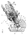
- FIG. 1 is a schematic perspective view of a gas turbine 10 having an axial-flow fluid machine blade (hereinafter, referred to as "stator blade") 60 according to this embodiment, showing a state in which the upper half portion of a casing is removed.
- stat blade an axial-flow fluid machine blade
- the gas turbine 10 includes a compressing unit (axial-flow fluid machine) 20 for compressing combustion air, a combustion unit 30 for combusting fuel injected into a high-pressure air fed from the compressing unit 20 and generating high-temperature combustion gas, and a turbine unit 40 positioned on the downstream side of the combustion unit 30 and driven by the combustion gas discharged out from the combustion unit 30 as main elements.
- the compressing unit 20 includes a rotor assembly 21 and a stator blade assembly 22.
- the rotor assembly 21 includes a shaft 21a arranged on a journal bearing 51 provided in a casing 50 and a plurality of rotor blade disks 21b provided on the shaft 21a.
- the rotor blade disks 21b each include a plurality of rotor blades 21c.
- the stator blade assembly 22 is arranged adjacent to the rotor blade disks 21b in the axial direction, and is divided into a plurality of segments circumferentially of the casing 50 and, for example, the stator blade assembly 22 divided into two each segments in the upper half portion and the lower half portion of the casing 50 constitutes each stator portion with four segments (that is, four stator blade assemblies) as one stage of a stator portion.
- Reference numeral 26 in Fig. 1 is a diffuser.
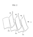
- the stator blade assembly 22 includes a plurality of stator blades 60 arranged in an annular shape, and introduces air flow to the rotor blades 21c (or the diffuser 26) positioned at the rear thereof.
- FIG. 3 is a plan view of the stator blade 60 viewed along an arrow A shown in Fig. 2 , that is, a view showing an outline of the stator blade 60 placed on a flat desk with a ventral side faced down viewed from above.
- the left side corresponds to the leading edge side
- the right side corresponds to the trailing edge side
- the upper side corresponds to the tip (distal end) side
- the lower side corresponds to the root (base) side.
- a leading edge 61 of the stator blade 60 is formed so as to assume a substantially U-shape in plan view in which the tip portion and the root portion project toward the upstream side (the upstream side with respect to the flow of combustion air).
- a trailing edge 62 of the stator blade 60 is formed so as to assume a substantially W-shape in plan view in which the tip portion, the mid-span portion and the root portion project toward the downstream side (the downstream side with respect to the flow of the combustion air).
- the stator blade 60 is manufactured in such a manner that the chord length near a portion at 20% Ht and the chord length near a portion at 80% Ht is shorter than the chord length near a portion at 50% Ht (in other words, in such a manner that the chord length near the portion at 20% Ht and the chord length near the portion at 80% Ht are minimized).
- the chord length near the portion at 50% Ht is the same as the chord length near the portion at 0% Ht and the chord length near the portion at 100% Ht.
- the portion at 0% Ht corresponds to the root of the stator blade 60 and the portion at 100% Ht corresponds to the distal end of the stator blade 60.
- the leading edge 61 is formed so as to assume the substantially U-shape in plan view and the trailing edge 62 assumes the substantially W-shape in plan view, so that the chord length of the entire stator blade 60 is reduced and the surface area of the entire stator blade 60 is reduced. Accordingly, the frictional loss of the stator blade 60 is reduced. Since the chord lengths of the stator blade 60 between the chip portion and the mid-span portion and between the mid-span portion and the root portion are reduced, and the surface areas of these areas are reduced, so that the frictional loss in these areas is reduced as shown by the broken line in Fig. 4 . A thick solid line in Fig.
- FIG. 4 represents the stator blade having the leading edge 61 shown in Fig. 3 and the rear edge formed straight from the root to the tip (that is, no convex and concave is formed from the root to the tip).
- the broken line in Fig. 4 represents the stator blade 60 manufactured in such a manner that the chord length near the portion at 25% Ht and the chord length near the portion at 75% Ht is shorter than the chord length near the portion at 50% Ht (in other words, in such a manner that the chord length near the portion at 25% Ht and the chord length near the portion at 75% Ht are minimized).
- stator blade 60 is manufactured in such a manner that the chord length near the portion at 50% Ht (mid-span portion) is longer than the chord lengths between the tip portion and the mid-span portion and between the mid-span portion and the root portion (for example, in such a manner that the chord length at 0% Ht and the cord length at 100% Ht become substantially the same), even when the working point is moved to the side having a higher pressure ratio than the rated point when the load is high, separation of the air flow near the portion at 50% Ht (mid-span portion) is prevented, and lowering of the surge resistant property is prevented.
- stator blade 60 is manufactured by paring the leading edge and the trailing edge (that is, it is not manufactured so as to add the tip portion, the mid-span portion and the root portion on the upstream side and/or the downstream side), upsizing in the axial direction is avoided.
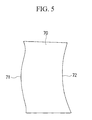
- a stator blade 70 in this embodiment is different from that in the first embodiment in that a leading edge 71 is formed so as to assume a substantially W-shape in plan view and a trailing edge 72 is formed so as to assume a substantially U-shape in plan view.
- Other components are the same as those in the first embodiment described above, and hence description of these components is omitted here.
- the leading edge 71 of the stator blade 70 is formed to assume a substantially W-shape in plan view in which the tip portion, the mid-span portion and the root portion project toward the upstream side (the upstream side with respect to the flow of combustion air).
- the trailing edge 72 of the stator blade 70 is formed so as to assume a substantially U-shape in plan view in which the tip portion and the root portion project toward the downstream side (the downstream side with respect to the flow of combustion air).
- the stator blade 70 is manufactured in such a manner that the chord length near a portion at 20% Ht and the chord length near a portion at 80% Ht is shorter than the chord length near a portion at 50% Ht (in other words, in such a manner that the chord length near the portion at 20% Ht and the chord length near the portion at 80% Ht are minimized).
- the chord length near the portion at 50% Ht is the same as the chord length near a portion at 0% Ht and the chord length near a portion at 100% Ht.
- the portion at 0% Ht corresponds to the root of the stator blade 70 and the portion at 100% Ht corresponds to the distal end of the stator blade 70.
- the stator blades 60, 70 are preferably specifically when it is used in a subsonic state.
- the stator blade is manufactured in such a manner that the chord length near a portion at 20% Ht and the chord length near a portion at 80% Ht is shorter than the chord length near a portion at 50% Ht (in other words, in such a manner that the chord length near the portion at 20% Ht and the chord length near the portion at 80% Ht are minimized).
- the present invention is not limited thereto, and for example, may be manufactured in such a manner that the chord length near a portion at 25% Ht and the chord length near a portion at 75% Ht is shorter than the chord length near a portion at 50% Ht.
- the point relating to the chord length such that the chord length of this part is set to be shorter than the chord length of that part is a matter to be changed as needed.
Landscapes
- Engineering & Computer Science (AREA)
- Mechanical Engineering (AREA)
- General Engineering & Computer Science (AREA)
- Physics & Mathematics (AREA)
- Fluid Mechanics (AREA)
- Structures Of Non-Positive Displacement Pumps (AREA)
- Turbine Rotor Nozzle Sealing (AREA)
Applications Claiming Priority (2)
| Application Number | Priority Date | Filing Date | Title |
|---|---|---|---|
| JP2006069135A JP4719038B2 (ja) | 2006-03-14 | 2006-03-14 | 軸流流体機械用翼 |
| PCT/JP2007/051436 WO2007105380A1 (fr) | 2006-03-14 | 2007-01-30 | Lame destinee a une machine a fluide a ecoulement axial |
Publications (3)
| Publication Number | Publication Date |
|---|---|
| EP1995469A1 true EP1995469A1 (fr) | 2008-11-26 |
| EP1995469A4 EP1995469A4 (fr) | 2013-08-14 |
| EP1995469B1 EP1995469B1 (fr) | 2015-01-07 |
Family
ID=38509219
Family Applications (1)
| Application Number | Title | Priority Date | Filing Date |
|---|---|---|---|
| EP07707667.7A Active EP1995469B1 (fr) | 2006-03-14 | 2007-01-30 | Lame destinee a une machine a fluide a ecoulement axial |
Country Status (6)
| Country | Link |
|---|---|
| US (1) | US8100658B2 (fr) |
| EP (1) | EP1995469B1 (fr) |
| JP (1) | JP4719038B2 (fr) |
| CN (1) | CN101379299B (fr) |
| CA (1) | CA2640697C (fr) |
| WO (1) | WO2007105380A1 (fr) |
Cited By (1)
| Publication number | Priority date | Publication date | Assignee | Title |
|---|---|---|---|---|
| EP3372786A1 (fr) * | 2017-03-09 | 2018-09-12 | Honeywell International Inc. | Aube de rotor de compresseur à haute pression avec bord d'attaque ayant un segment d'indentation |
Families Citing this family (10)
| Publication number | Priority date | Publication date | Assignee | Title |
|---|---|---|---|---|
| DE102008055824B4 (de) * | 2007-11-09 | 2016-08-11 | Alstom Technology Ltd. | Dampfturbine |
| FR2981118B1 (fr) * | 2011-10-07 | 2016-01-29 | Snecma | Disque aubage monobloc pourvu d'aubes a profil de pied adapte |
| EP2669475B1 (fr) * | 2012-06-01 | 2018-08-01 | Safran Aero Boosters SA | Aube à profile en S de compresseur de turbomachine axiale, compresseur et turbomachine associée |
| EP2964895A4 (fr) * | 2013-03-07 | 2016-12-28 | United Technologies Corp | Pale de soufflante hybride pour moteurs à réaction |
| US20150275675A1 (en) * | 2014-03-27 | 2015-10-01 | General Electric Company | Bucket airfoil for a turbomachine |
| US10876536B2 (en) | 2015-07-23 | 2020-12-29 | Onesubsea Ip Uk Limited | Surge free subsea compressor |
| US11933323B2 (en) | 2015-07-23 | 2024-03-19 | Onesubsea Ip Uk Limited | Short impeller for a turbomachine |
| EP3379083B1 (fr) * | 2017-03-21 | 2023-08-23 | OneSubsea IP UK Limited | Hélice courte pour turbomachine |
| CN113606076B (zh) * | 2021-09-07 | 2022-08-26 | 清华大学 | 一种基于叶片头部凸起结构的流动控制方法及具有其的叶轮 |
| US12509988B2 (en) | 2024-06-14 | 2025-12-30 | Pratt & Whitney Canada Corp. | Turbine engine airfoil |
Family Cites Families (18)
| Publication number | Priority date | Publication date | Assignee | Title |
|---|---|---|---|---|
| JPS3615301B1 (fr) | 1958-08-21 | 1961-09-04 | ||
| JPS5264008A (en) | 1975-11-21 | 1977-05-27 | Le Metarichiesukii Zabuodo Im | Axiallflow turboocompressors |
| US4995787A (en) * | 1989-09-18 | 1991-02-26 | Torrington Research Company | Axial flow impeller |
| DE4344189C1 (de) * | 1993-12-23 | 1995-08-03 | Mtu Muenchen Gmbh | Axial-Schaufelgitter mit gepfeilten Schaufelvorderkanten |
| JPH0893404A (ja) * | 1994-09-27 | 1996-04-09 | Toshiba Corp | タービンノズルおよびタービン動翼 |
| US5706647A (en) | 1994-11-15 | 1998-01-13 | Solar Turbines Incorporated | Airfoil structure |
| US5961289A (en) * | 1995-11-22 | 1999-10-05 | Deutsche Forshungsanstalt Fur Luft-Und Raumfahrt E.V. | Cooling axial flow fan with reduced noise levels caused by swept laminar and/or asymmetrically staggered blades |
| JPH09151704A (ja) * | 1995-11-30 | 1997-06-10 | Toshiba Corp | 軸流回転機械 |
| JPH10103002A (ja) | 1996-09-30 | 1998-04-21 | Toshiba Corp | 軸流流体機械用翼 |
| JPH10184303A (ja) | 1996-12-26 | 1998-07-14 | Ishikawajima Harima Heavy Ind Co Ltd | ストール防止翼列構造 |
| JP3559152B2 (ja) * | 1997-10-13 | 2004-08-25 | 新潟原動機株式会社 | ターボ機械の静翼及びその組立方法 |
| JP2000145402A (ja) | 1998-11-12 | 2000-05-26 | Mitsubishi Heavy Ind Ltd | 軸流タービン翼列 |
| US6328533B1 (en) * | 1999-12-21 | 2001-12-11 | General Electric Company | Swept barrel airfoil |
| US6554564B1 (en) * | 2001-11-14 | 2003-04-29 | United Technologies Corporation | Reduced noise fan exit guide vane configuration for turbofan engines |
| JP2004028065A (ja) | 2002-06-28 | 2004-01-29 | Toshiba Corp | タービンノズル |
| US6749401B2 (en) * | 2002-07-22 | 2004-06-15 | Arthur Vanmoor | Hydrodynamically and aerodynamically optimized leading edge structure for propellers, wings, and airfoils |
| JP2006291889A (ja) | 2005-04-13 | 2006-10-26 | Mitsubishi Heavy Ind Ltd | タービン翼列エンドウォール |
| FR2908152B1 (fr) * | 2006-11-08 | 2009-02-06 | Snecma Sa | Aube en fleche de turbomachine |
-
2006
- 2006-03-14 JP JP2006069135A patent/JP4719038B2/ja not_active Expired - Lifetime
-
2007
- 2007-01-30 WO PCT/JP2007/051436 patent/WO2007105380A1/fr not_active Ceased
- 2007-01-30 CN CN200780004025.7A patent/CN101379299B/zh active Active
- 2007-01-30 US US12/223,337 patent/US8100658B2/en active Active
- 2007-01-30 EP EP07707667.7A patent/EP1995469B1/fr active Active
- 2007-01-30 CA CA2640697A patent/CA2640697C/fr active Active
Cited By (2)
| Publication number | Priority date | Publication date | Assignee | Title |
|---|---|---|---|---|
| EP3372786A1 (fr) * | 2017-03-09 | 2018-09-12 | Honeywell International Inc. | Aube de rotor de compresseur à haute pression avec bord d'attaque ayant un segment d'indentation |
| US10718214B2 (en) | 2017-03-09 | 2020-07-21 | Honeywell International Inc. | High-pressure compressor rotor with leading edge having indent segment |
Also Published As
| Publication number | Publication date |
|---|---|
| WO2007105380A1 (fr) | 2007-09-20 |
| EP1995469B1 (fr) | 2015-01-07 |
| JP4719038B2 (ja) | 2011-07-06 |
| CA2640697C (fr) | 2011-03-15 |
| JP2007247453A (ja) | 2007-09-27 |
| CN101379299B (zh) | 2014-06-18 |
| US8100658B2 (en) | 2012-01-24 |
| CA2640697A1 (fr) | 2007-09-20 |
| EP1995469A4 (fr) | 2013-08-14 |
| CN101379299A (zh) | 2009-03-04 |
| US20090169391A1 (en) | 2009-07-02 |
Similar Documents
| Publication | Publication Date | Title |
|---|---|---|
| CA2640697C (fr) | Aube de machine a fluide a ecoulement axial | |
| US7121792B1 (en) | Nozzle vane with two slopes | |
| US6899526B2 (en) | Counterstagger compressor airfoil | |
| US8186962B2 (en) | Fan rotating blade for turbofan engine | |
| CN103184898B (zh) | 具有导流凹槽的燃气涡轮喷嘴 | |
| EP2631435A1 (fr) | Aube de stator variable de moteur de turbine | |
| CN103184897B (zh) | 具有导流栅的燃气涡轮喷嘴 | |
| EP1555392B1 (fr) | Etage redresseur en porte-à-faux | |
| US10190423B2 (en) | Shrouded blade for a gas turbine engine | |
| EP3722555B1 (fr) | Section de turbine ayant contournage de paroi d'extrémité non axisymétrique avec crête à mi-passage | |
| US9476317B2 (en) | Forward step honeycomb seal for turbine shroud | |
| WO2005111378A1 (fr) | Distribution de la courbure d'une pale de ventilateur pour un ventilateur a rapport eleve des pressions dans la partie centrale | |
| EP1118747A3 (fr) | Aube pour une turbomachine axiale | |
| EP1942252A2 (fr) | Extrémité d' aube pour un ensemble rotor | |
| EP2378075A1 (fr) | Aube rotorique et moteur à turbine à gaz associé | |
| CA2567940C (fr) | Methodes et dispositifs applicables aux turbines a gaz | |
| EP1978212A2 (fr) | Ensemble statorique pour moteur à turbine à gaz | |
| EP2221454A1 (fr) | Aube carénée de turbine à gaz | |
| US10822960B2 (en) | Turbine blade cooling | |
| US20200011188A1 (en) | Blade for a gas turbine engine | |
| JP5357908B2 (ja) | 軸流流体機械用翼 | |
| JP5087149B2 (ja) | 軸流流体機械用翼 |
Legal Events
| Date | Code | Title | Description |
|---|---|---|---|
| PUAI | Public reference made under article 153(3) epc to a published international application that has entered the european phase |
Free format text: ORIGINAL CODE: 0009012 |
|
| 17P | Request for examination filed |
Effective date: 20080716 |
|
| AK | Designated contracting states |
Kind code of ref document: A1 Designated state(s): CH DE FR GB IT LI |
|
| DAX | Request for extension of the european patent (deleted) | ||
| RBV | Designated contracting states (corrected) |
Designated state(s): CH DE FR GB IT LI |
|
| A4 | Supplementary search report drawn up and despatched |
Effective date: 20130717 |
|
| RIC1 | Information provided on ipc code assigned before grant |
Ipc: F01D 9/02 20060101ALI20130710BHEP Ipc: F04D 29/32 20060101ALI20130710BHEP Ipc: F01D 5/14 20060101ALI20130710BHEP Ipc: F04D 29/38 20060101AFI20130710BHEP |
|
| GRAP | Despatch of communication of intention to grant a patent |
Free format text: ORIGINAL CODE: EPIDOSNIGR1 |
|
| INTG | Intention to grant announced |
Effective date: 20140624 |
|
| GRAS | Grant fee paid |
Free format text: ORIGINAL CODE: EPIDOSNIGR3 |
|
| GRAA | (expected) grant |
Free format text: ORIGINAL CODE: 0009210 |
|
| AK | Designated contracting states |
Kind code of ref document: B1 Designated state(s): CH DE FR GB IT LI |
|
| RAP1 | Party data changed (applicant data changed or rights of an application transferred) |
Owner name: MITSUBISHI HITACHI POWER SYSTEMS, LTD. |
|
| REG | Reference to a national code |
Ref country code: GB Ref legal event code: FG4D |
|
| REG | Reference to a national code |
Ref country code: CH Ref legal event code: EP |
|
| REG | Reference to a national code |
Ref country code: DE Ref legal event code: R096 Ref document number: 602007039947 Country of ref document: DE Effective date: 20150226 |
|
| RAP2 | Party data changed (patent owner data changed or rights of a patent transferred) |
Owner name: MITSUBISHI HITACHI POWER SYSTEMS, LTD. |
|
| REG | Reference to a national code |
Ref country code: CH Ref legal event code: PL |
|
| REG | Reference to a national code |
Ref country code: DE Ref legal event code: R097 Ref document number: 602007039947 Country of ref document: DE |
|
| PG25 | Lapsed in a contracting state [announced via postgrant information from national office to epo] |
Ref country code: LI Free format text: LAPSE BECAUSE OF NON-PAYMENT OF DUE FEES Effective date: 20150131 Ref country code: CH Free format text: LAPSE BECAUSE OF NON-PAYMENT OF DUE FEES Effective date: 20150131 |
|
| PLBE | No opposition filed within time limit |
Free format text: ORIGINAL CODE: 0009261 |
|
| STAA | Information on the status of an ep patent application or granted ep patent |
Free format text: STATUS: NO OPPOSITION FILED WITHIN TIME LIMIT |
|
| 26N | No opposition filed |
Effective date: 20151008 |
|
| REG | Reference to a national code |
Ref country code: FR Ref legal event code: ST Effective date: 20151116 |
|
| GBPC | Gb: european patent ceased through non-payment of renewal fee |
Effective date: 20150407 |
|
| PG25 | Lapsed in a contracting state [announced via postgrant information from national office to epo] |
Ref country code: IT Free format text: LAPSE BECAUSE OF FAILURE TO SUBMIT A TRANSLATION OF THE DESCRIPTION OR TO PAY THE FEE WITHIN THE PRESCRIBED TIME-LIMIT Effective date: 20150107 |
|
| PG25 | Lapsed in a contracting state [announced via postgrant information from national office to epo] |
Ref country code: GB Free format text: LAPSE BECAUSE OF NON-PAYMENT OF DUE FEES Effective date: 20150407 |
|
| PG25 | Lapsed in a contracting state [announced via postgrant information from national office to epo] |
Ref country code: FR Free format text: LAPSE BECAUSE OF NON-PAYMENT OF DUE FEES Effective date: 20150309 |
|
| REG | Reference to a national code |
Ref country code: DE Ref legal event code: R082 Ref document number: 602007039947 Country of ref document: DE Representative=s name: HENKEL & PARTNER MBB PATENTANWALTSKANZLEI, REC, DE Ref country code: DE Ref legal event code: R081 Ref document number: 602007039947 Country of ref document: DE Owner name: MITSUBISHI POWER, LTD., JP Free format text: FORMER OWNER: MITSUBISHI HITACHI POWER SYSTEMS, LTD., YOKOHAMA-SHI, KANAGAWA, JP |
|
| PGFP | Annual fee paid to national office [announced via postgrant information from national office to epo] |
Ref country code: DE Payment date: 20251203 Year of fee payment: 20 |