EP1995497A1 - Ölzufuhrsystem für ein Fahrzeug - Google Patents
Ölzufuhrsystem für ein Fahrzeug Download PDFInfo
- Publication number
- EP1995497A1 EP1995497A1 EP08009500A EP08009500A EP1995497A1 EP 1995497 A1 EP1995497 A1 EP 1995497A1 EP 08009500 A EP08009500 A EP 08009500A EP 08009500 A EP08009500 A EP 08009500A EP 1995497 A1 EP1995497 A1 EP 1995497A1
- Authority
- EP
- European Patent Office
- Prior art keywords
- gear ratio
- oil
- hydraulic
- pressure
- electric motor
- Prior art date
- Legal status (The legal status is an assumption and is not a legal conclusion. Google has not performed a legal analysis and makes no representation as to the accuracy of the status listed.)
- Withdrawn
Links
- 239000003921 oil Substances 0.000 claims abstract description 106
- 239000010720 hydraulic oil Substances 0.000 claims abstract description 58
- 230000005540 biological transmission Effects 0.000 claims description 54
- 238000010586 diagram Methods 0.000 description 5
- 230000001133 acceleration Effects 0.000 description 3
- 230000006870 function Effects 0.000 description 2
- 239000008186 active pharmaceutical agent Substances 0.000 description 1
- 230000000694 effects Effects 0.000 description 1
- 239000007858 starting material Substances 0.000 description 1
Images




Classifications
-
- F—MECHANICAL ENGINEERING; LIGHTING; HEATING; WEAPONS; BLASTING
- F16—ENGINEERING ELEMENTS AND UNITS; GENERAL MEASURES FOR PRODUCING AND MAINTAINING EFFECTIVE FUNCTIONING OF MACHINES OR INSTALLATIONS; THERMAL INSULATION IN GENERAL
- F16H—GEARING
- F16H61/00—Control functions within control units of change-speed- or reversing-gearings for conveying rotary motion ; Control of exclusively fluid gearing, friction gearing, gearings with endless flexible members or other particular types of gearing
- F16H61/0021—Generation or control of line pressure
- F16H61/0025—Supply of control fluid; Pumps therefor
-
- F—MECHANICAL ENGINEERING; LIGHTING; HEATING; WEAPONS; BLASTING
- F16—ENGINEERING ELEMENTS AND UNITS; GENERAL MEASURES FOR PRODUCING AND MAINTAINING EFFECTIVE FUNCTIONING OF MACHINES OR INSTALLATIONS; THERMAL INSULATION IN GENERAL
- F16H—GEARING
- F16H61/00—Control functions within control units of change-speed- or reversing-gearings for conveying rotary motion ; Control of exclusively fluid gearing, friction gearing, gearings with endless flexible members or other particular types of gearing
- F16H61/66—Control functions within control units of change-speed- or reversing-gearings for conveying rotary motion ; Control of exclusively fluid gearing, friction gearing, gearings with endless flexible members or other particular types of gearing specially adapted for continuously variable gearings
- F16H61/662—Control functions within control units of change-speed- or reversing-gearings for conveying rotary motion ; Control of exclusively fluid gearing, friction gearing, gearings with endless flexible members or other particular types of gearing specially adapted for continuously variable gearings with endless flexible members
- F16H2061/66286—Control for optimising pump efficiency
-
- F—MECHANICAL ENGINEERING; LIGHTING; HEATING; WEAPONS; BLASTING
- F16—ENGINEERING ELEMENTS AND UNITS; GENERAL MEASURES FOR PRODUCING AND MAINTAINING EFFECTIVE FUNCTIONING OF MACHINES OR INSTALLATIONS; THERMAL INSULATION IN GENERAL
- F16H—GEARING
- F16H61/00—Control functions within control units of change-speed- or reversing-gearings for conveying rotary motion ; Control of exclusively fluid gearing, friction gearing, gearings with endless flexible members or other particular types of gearing
- F16H61/66—Control functions within control units of change-speed- or reversing-gearings for conveying rotary motion ; Control of exclusively fluid gearing, friction gearing, gearings with endless flexible members or other particular types of gearing specially adapted for continuously variable gearings
- F16H61/662—Control functions within control units of change-speed- or reversing-gearings for conveying rotary motion ; Control of exclusively fluid gearing, friction gearing, gearings with endless flexible members or other particular types of gearing specially adapted for continuously variable gearings with endless flexible members
- F16H61/66231—Control functions within control units of change-speed- or reversing-gearings for conveying rotary motion ; Control of exclusively fluid gearing, friction gearing, gearings with endless flexible members or other particular types of gearing specially adapted for continuously variable gearings with endless flexible members controlling shifting exclusively as a function of speed
Definitions
- the present invention relates to a oil supply system provided for a motor vehicle, such as an automobile, and relates particularly to a oil supply system that supplies hydraulic oil to an automatic transmission of the motor vehicle at a required flow rate based on the operating state of the motor vehicle.
- a motor vehicle such as an automobile, is equipped with a oil supply system that comprises: a variable-transmission hydraulic controller for controlling an automatic transmission by hydraulic oil in order to match the actual automatic transmission gear ratio with a target gear ratio; and a controller for transmitting operation instructions to the variable-transmission hydraulic control apparatus.
- the oil supply system supplies the hydraulic pressure and the volume of oil required to produce an automatic transmission speed change.
- An automobile 40 is provided with a belt type, Continuously Variable Transmission (CVT) that steplessly changes transmission gear ratio and that is employed mainly for Kei cars or K-cars (Japanese small automobile category) and compact automobiles.
- CVT Continuously Variable Transmission
- the transaxle 42 includes: a drive force switching mechanism 45, constituted by a torque converter 43 and a forward/rearward switching device 44; a belt-type continuously variable transmission (hereinafter referred to as a CVT) 46 including a primary pulley 46a on the input side coupled with the drive force switching mechanism 45 for drive force transmission; and speed reduction gears 47 coupled with a secondary pulley 46b on the output side of the CVT 46.
- a V-belt 46v is wound around the primary pulley 46a and the secondary pulley 46b, and the drive force which is generated by the engine 41 is transmitted to the secondary pulley 46b through frictional force generated between the V-belt 46v and the pulleys 46a and 46b.
- a starter 41s for starting the engine 41 is mounted in the automobile 40 shown in Figs. 5A and 5B .
- a vehicular oil supply system 48s mounted in the automobile 40 includes: a variable-transmission hydraulic controller 48 which employs hydraulic oil to control the CVT 46 to match the actual gear ratio ⁇ of the CVT 46 with a target ratio ⁇ *; and a CVT controller 49 for transmitting control signals as operation instructions to the variable-transmission hydraulic controller 48.
- the variable-transmission hydraulic controller 48 is provided for a hydraulic control unit 48p together with a gripping pressure controller 46c that uses hydraulic oil to control the belt gripping pressure at the secondary pulley 46b based on a predetermined gripping pressure control condition.
- the gripping pressure controller 46c is connected to the CVT controller 49 via a linear solenoid 46L, the operation of which is performed in accordance with control signals received from the CVT controller 49.
- an input shaft rotation speed sensor Sa and an output shaft rotation speed sensor Sb are arranged for the primary pulley 46a and the secondary pulley 46b of the CVT 46, respectively.
- the CVT controller 49 controls the operation of the variable-transmission hydraulic controller 48 to apply, to the primary pulley 46a, hydraulic oil of the oil pressure P [MPa] having the obtained required pressure value. Thereafter, in accordance with the thus obtained result, the variable transmission operation of the CVT 46 is performed.
- the variable-transmission hydraulic controller 48 includes: an electromagnetic switching valve 48a and a flow control valve 48b for an shift-up, which reduce the gear ratio v; and an electromagnetic switching valve 48c and a flow control valve 48d for a shift-down, which increase the gear ratio v.
- a mechanical hydraulic pump 60 is driven by the rotational force generated by the rotary shaft (crank shaft 41a) of the engine 41 (see Fig. 5A ), and is always rotated at high speed based on the rotational speed of the engine 41.
- the mechanical hydraulic pump 60 serves as a hydraulic source for the speed change operation of the CVT 46.
- a predetermined control pressure is output to the flow control valve 48b, and a line pressure adjusted based on the control pressure is supplied along a supply path 46d to the hydraulic cylinder of the primary pulley 46a.
- a line pressure adjusted based on the control pressure is supplied along a supply path 46d to the hydraulic cylinder of the primary pulley 46a.
- the flow control valve 48b permits an oil line path 46g and the supply path 46d to communicate with each other in a predetermined flow area in cross section, and exert a predetermined oil pressure in this area (see, for example, JP-A-2001-330135 ).
- the CVT controller 49 provides hydraulic control (speed change control) for the pair of flow control valves 48b and 48d for an shift-up and a shift-down (in the variable-transmission hydraulic controller 48), in accordance with a vehicle speed and an accelerator position, thereby performing the speed change operation by the CVT 46.
- the drain port 48e is opened and hydraulic oil in the primary pulley 46a is discharged at a predetermined flow rate along a discharge path 46e to reduce the oil pressure in the hydraulic cylinder of the primary pulley 46a. Therefore, based on the shift operation, the oil pressure is not quickly reduced and the variable transmission operation may not be smoothly performed.
- the oil supply system 48s is employed for the CVT 46, the delay in the reduction of the oil pressure in the primary pulley 46a may cause V-belt 46v slippage, and a drive force loss may occur during the transmission of the drive force generated by the engine 41.
- the present invention resolves the above described problems, and has as one objective the provision of a oil supply system that can rapidly supply, under a required pressure, the hydraulic oil that, based on a change in the operating state of a motor vehicle, is required by the automatic transmission of the motor vehicle, and that can perform a smooth variable transmission operation and reduce the drive force required to supply the hydraulic oil to the automatic transmission.
- the present invention provides the following arrangements.
- an electric motor that serves as a drive source for the motor-driven oil pump is rotated, in accordance with the operating state of the motor vehicle, forward to increase the pressure for the hydraulic oil to be supplied to the automatic transmission, or rearward to reduce the pressure. Therefore, when a low hydraulic pressure is required by the automatic transmission, the electric motor is rotated in the reverse direction, so that the pressure for the hydraulic oil to be supplied to the automatic transmission can be easily and rapidly reduced.
- the oil pressure for the hydraulic oil to be supplied to the automatic transmission can be changed in accordance with the rotational speed, and can be adjusted to obtain an oil pressure (for the amount that must be supplied) required for the variable transmission operation of the automatic transmission.
- the actual gear ratio, for the automatic transmission of the motor vehicle, and the target gear ratio are compared, and when the target gear ratio is smaller than the actual gear ratio, the electric motor is rotated forward, and when the target gear ratio is greater than the actual gear ratio, the electric motor is rotated rearward until the two ratios match. Therefore, the operation during which the oil pressure for hydraulic oil to be supplied to the automatic transmission can be adjusted to obtain the oil pressure required for the variable transmission operation of the automatic transmission can be performed more appropriately.
- the hydraulic oil in accordance with a change in the operating state of the motor vehicle, the hydraulic oil can be quickly supplied, at a pressure value required by the automatic transmission of the motor vehicle, and the variable transmission operation can be smoothly performed, and the drive force for supplying the hydraulic oil to the automatic transmission can be reduced.
- a oil supply system according to the embodiment of the invention is mounted in an automobile (a motor vehicle) and on a vehicle driving assembly shown in Figs. 5A and 5B , unless a special explanatory note is given. Therefore, the reference numerals employed above are provided for corresponding components, and no further explanation for them will be given.
- a oil supply system 58s includes: a variable-transmission hydraulic controller 58, which employs hydraulic oil to adjust a gear ratio ⁇ for a CVT (an automatic transmission) 46 to a target gear ratio ⁇ *; and a CVT controller 49 for transmitting operation instructions to the variable-transmission hydraulic controller 58.
- the CVT controller 49 incorporates a memory 49m for storing map and an arithmetic expression in form of data and program.
- a memory 49m for storing map and an arithmetic expression in form of data and program.
- an output value requested by a driver such as the degree of depression of an accelerator pedal
- an operating state such as a vehicle speed are used as parameters for setting the condition of the gear ratio (the vehicle speed corresponds to the rotational speed of a secondary pulley 46b).
- the variable-transmission hydraulic controller 58 includes: a three-port electromagnetic switching valve (a control valve) 58v, through which hydraulic oil from a motor-driven oil pump 10 is supplied to a primary pulley 46a and which can select one of a path for circulating hydraulic oil from the primary pulley 46a via the motor-driven oil pump 10 to an oil pan 52, a path for halting the distribution of hydraulic oil, and a path for feeding hydraulic oil from the motor-driven oil pump 10 to the oil pan 52; and the motor-driven oil pump 10 which supplies hydraulic oil from the oil pan 52 via the electromagnetic switching valve 58v to the primary pulley 46a.
- a control valve 58v
- the motor-driven oil pump 10 in the embodiment includes: an internal gear pump (a pump portion) 2 which can supply hydraulic oil both to the primary pulley 46a and to the oil pan 52; and an electric motor 3 which drives the internal gear pump 2.
- the motor-driven oil pump 10 includes a housing main body 1 that has an internal storage space and that is formed of a pump housing 11, in which the internal gear pump 2 is stored, and a motor housing 12, which is integrated with the pump housing 11 and in which the electric motor 3 is stored.
- the internal gear pump 2 includes: an outer rotor 21, which has internal teeth of a Parachoid (registered trademark) type, and an inner rotor 22, which has external teeth of the same type and externally engages the outer rotor 21.
- an outer rotor 21 which has internal teeth of a Parachoid (registered trademark) type
- an inner rotor 22 which has external teeth of the same type and externally engages the outer rotor 21.
- the electric motor 3 includes: a motor rotor 37, which permits the inner rotor 22 to pivot at a distal end 37t; and a stator core 32, which encloses the periphery of the motor rotor 37 and which rotates the motor rotor 37 by employing an electromagnetic force generated by energizing a coil 33.
- the motor rotor 37 is rotatably supported at the housing main body 1 by a first roller bearing 5a and a second roller bearing 5b.
- arc shaped pump chambers 25 are formed between the tooth spaces 21a and 22a in the rotors 21 and 22, and as the rotors 21 and 22 are rotated either forward or rearward, a low pressure portion is formed on the intake side of the pump chambers 25, while a high pressure portion is formed on the output side of the pump chambers 25.
- a first crescent-shaped port 13ra and a second crescent-shaped port 13rb are formed in the pump plate 13 to communicate with the pump chambers 25, and a first port 13a and a second port 13b are also formed, to communicate with the first and the second ports 13ra and 13rb, respectively, and to be connected to external tubes.
- the CVT controller 49 performs the program stored (with included data) in the memory 49m (see Fig. 1 ) and transmits an operation instruction from the CVT controller 49 to the variable-transmission hydraulic controller 58. Then, based on the operation instruction, the electric motor 3 controls the forward or rearward rotations of the rotors 21 and 22.
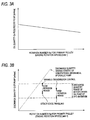
- the map data representing a relationship between a rotation number Np (an engine rotation speed) [min -1 ], for the primary pulley 46a shown in Fig. 3A , and a required oil quantity Qn [m 3 /min], for the motor-driven oil pump 10, is stored in the memory 49m.
- the CVT controller 49 switches the electromagnetic switching valve 58v in Fig. 1 and rotates the electric motor 3 of the motor-driven oil pump 10 in the reverse direction, thereby providing a state in which the hydraulic oil returns from the primary pulley 46a to the oil pan 62, via the valve 58v and the motor-driven oil pump 10. Then, as shown in Fig. 7 , the primary pulley 46a is set in the state existing prior to the stroke, i.e., a state A in which the width of the V-shaped groove 46f is extended to the maximum.
- the CVT controller 49 controls the operation of the motor-driven oil pump 10 and the electromagnetic switching valve 58v. Then, the motor-driven oil pump 10 is rotated forward until the actual gear ratio ⁇ matches the target gear ratio ⁇ *, and a small quantity of hydraulic oil (low pressure) is supplied via the electromagnetic switching valve 58v shown in Fig. 1 to the primary pulley 46a of the CVT 46.
- the CVT controller 49 controls the operation of the motor-driven oil pump 10 and the electromagnetic switching valve 58v.
- the motor-driven oil pump 10 is rotated forward at high speed, so that the actual gear ratio ⁇ matches the target gear ratio ⁇ *, and a larger quantity (high pressure propelled) of hydraulic oil than in the low or middle range is supplied, via the electromagnetic switching valve 58v, to the primary pulley 46a of the CVT 46.
- the stroke of the primary pulley 46a is increased, and a state B is provided in which the width of the V-shaped groove 46f is narrowed.
- the CVT controller 49 controls the operation of motor-driven oil pump 10 and the electromagnetic switching valve 58v. Then, the motor-driven (by electric motor 3) oil pump 10 is rotated in the reverse direction, until the actual gear ratio ⁇ matches the target gear ratio ⁇ *, and a line pressure owing to the hydraulic oil, the pressure of which is below the high rotation range, is applied via the electromagnetic switching valve 58v in Fig. 1 to the primary pulley 46a of the CVT 46.
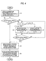
- the CVT controller 49 performs the processing shown in the flowchart in Fig. 4 as the timer interrupt processing every predetermined period of time (e.g., 10 msec), and controls the amount of hydraulic oil to be discharged from the motor-driven oil pump 10.
- step S3 it is determined that the automobile 40 is traveling in the steady state and a comparatively small quantity of hydraulic oil is required.
- the quantity Qn [m 3 /min] of oil required by the motor-driven oil pump 10 is calculated based on the rotational speed of the rotary shaft of the engine 41, i.e., the rotation number Np for the primary pulley 46a.
- step S5 it is determined that the automobile 40 is traveling in the unsteady state, and the target gear ratio ⁇ * and the actual gear ratio ⁇ are compared.
- the target gear ratio ⁇ * ⁇ the actual gear ratio v, i.e., a deviation ⁇ ⁇ 0
- step S6 the electric motor 3 is rotated forward, in accordance with the deviation ⁇ , by a PID controller, for example, until the deviation ⁇ becomes zero.
- step S7 the electric motor 3 is rotated rearward, in accordance with the target gear ratio ⁇ *, by the PID control, for example, until the deviation ⁇ becomes zero.
- the electric motor 3 need only be rotated in the reverse direction, so that the pressure of hydraulic oil to be supplied to the CVT 46 can be easily and rapidly reduced.
- step S8 it is judged as to whether the actual gear ratio ⁇ matches the target gear ratio ⁇ * .
- the target gear ratio ⁇ * the actual gear ratio ⁇ (steady-state traveling)
- program control is shifted to step S3.
- the target gear ratio ⁇ * the actual gear ratio ⁇ (non-steady-state traveling)
- program control is returned to step S5.
- a drive control signal DS is calculated based on the oil quantity Qn required by the motor-driven oil pump 10, and is output to the variable-transmission hydraulic controller 58. Thereafter, the timer interrupt processing is terminated, and program control returns to the main program.
- the target gear ratio ⁇ * is compared with the actual gear ratio ⁇ of the CVT 46, and when it is determined that the target gear ratio ⁇ * ⁇ the actual gear ratio v, the electric motor 3 is rotated forward. When it is determined that the target gear ratio v* > the actual gear ratio v, the electric motor 3 is rotated rearward, until the two gear ratios match. Therefore, the oil pressure of hydraulic oil to be supplied to the CVT 46 can be more accurately adjusted to a pressure value required for the variable transmission operation.
- the pressure of hydraulic oil to be supplied to the primary pulley 46a of the CVT 46 is adjusted by rotating the electric motor 3 forward or rearward. As a result, the pressure of hydraulic oil to be supplied to the CVT 46 can be rapidly and exactly adjusted to a required pressure value according to the operating state of the automobile 40.
- the motor-driven oil pump 10 includes the internal gear pump 2 and the electric motor 3 that rotates the pump 10, this oil pump 10 is superior in maintaining a constant flow rate, and a pulsating flow rarely occurs. As a result, the oil supply system 58s that generates little noise during operation can be provided.
- This embodiment may be modified as follows.
- a belt-type continuously variable transmission has been employed as an automatic transmission that employs the oil supply system 58s to control oil pressure required for a variable transmission operation.
- the technical idea of this invention is not limited to this, and the present invention can also be applied for another type of automatic transmission in which, by rotating a motor-driven oil pump 10 (electric motor 3) forward or rearward, the pressure of hydraulic oil to be supplied to a automatic transmission can be rapidly and exactly adjusted to a required pressure value based on the operating state of a motor vehicle.
- the rotational speed of the rotary shaft of the engine 41 has been employed as the operating state of the automobile (motor vehicle) 40.
- the technical idea of the invention is not limited to this, and the vehicle velocity (rotation speed of wheels) of an automobile (motor vehicle) may be employed as the operating state of the automobile.
- the internal gear pump 2 has been employed as the pump portion of the motor-driven oil pump 10.
- another pump such as an external gear pump
- the motor-driven oil pump 10 has been rotated forward or rearward, and the pressure of hydraulic oil to be supplied to the automatic transmission has been rapidly and exactly adjusted to a required pressure value according to the operating state of the automobile 40.
- a motor-driven oil pump that can only be rotated forward may be employed.
- an electromagnetic switching valve switches between the intake side and the outlet side of this motor-driven oil pump to connect to the primary pulley 46a of the CVT 46, so that the same function as the forward and rearward rotating function can be provided.
Landscapes
- Engineering & Computer Science (AREA)
- General Engineering & Computer Science (AREA)
- Mechanical Engineering (AREA)
- Control Of Transmission Device (AREA)
Applications Claiming Priority (1)
| Application Number | Priority Date | Filing Date | Title |
|---|---|---|---|
| JP2007138921A JP2008291933A (ja) | 2007-05-25 | 2007-05-25 | 車両用オイル供給システム |
Publications (1)
| Publication Number | Publication Date |
|---|---|
| EP1995497A1 true EP1995497A1 (de) | 2008-11-26 |
Family
ID=39712269
Family Applications (1)
| Application Number | Title | Priority Date | Filing Date |
|---|---|---|---|
| EP08009500A Withdrawn EP1995497A1 (de) | 2007-05-25 | 2008-05-23 | Ölzufuhrsystem für ein Fahrzeug |
Country Status (3)
| Country | Link |
|---|---|
| US (1) | US20080300075A1 (de) |
| EP (1) | EP1995497A1 (de) |
| JP (1) | JP2008291933A (de) |
Cited By (2)
| Publication number | Priority date | Publication date | Assignee | Title |
|---|---|---|---|---|
| GB2475844A (en) * | 2009-12-01 | 2011-06-08 | Gm Global Tech Operations Inc | Oil supply system with an electric pump mounted in a valve body or an oil pan |
| RU2505724C1 (ru) * | 2010-03-09 | 2014-01-27 | Ниссан Мотор Ко., Лтд. | Автоматическая трансмиссия и способ ее гидравлического управления |
Families Citing this family (3)
| Publication number | Priority date | Publication date | Assignee | Title |
|---|---|---|---|---|
| US10047860B2 (en) * | 2016-06-02 | 2018-08-14 | GM Global Technology Operations LLC | Pump switching control systems and methods for continuously variable transmissions |
| US10982764B2 (en) | 2017-08-23 | 2021-04-20 | Nissan Motor Co., Ltd. | Control method and control device for continuously variable transmission |
| US10571016B2 (en) | 2018-01-03 | 2020-02-25 | GM Global Technology Operations LLC | Electronic transmission range selection for a continuously variable transmission |
Citations (3)
| Publication number | Priority date | Publication date | Assignee | Title |
|---|---|---|---|---|
| JP2001330135A (ja) | 2000-05-23 | 2001-11-30 | Toyota Motor Corp | ベルト式無段変速機の制御装置 |
| WO2006016797A1 (en) * | 2004-08-13 | 2006-02-16 | Robert Bosch Gmbh | Continuously variable transmission provided with a set of hydraulic pumps |
| WO2008050687A1 (en) * | 2006-10-23 | 2008-05-02 | Jtekt Corporation | Control device for stepless transmission, flow rate control method, and flow rate control device |
Family Cites Families (7)
| Publication number | Priority date | Publication date | Assignee | Title |
|---|---|---|---|---|
| JPS62143744A (ja) * | 1985-12-19 | 1987-06-27 | Fuji Heavy Ind Ltd | 車両用無段変速機の変速比制御装置 |
| DE19908250A1 (de) * | 1999-02-25 | 2000-08-31 | Zahnradfabrik Friedrichshafen | Übersetzungsregelung eines stufenlosen Automatgetriebes |
| DE19920378C2 (de) * | 1999-05-04 | 2002-11-07 | Zahnradfabrik Friedrichshafen | Automatisch gesteuertes Getriebe |
| DE10033201A1 (de) * | 2000-07-07 | 2002-01-17 | Zf Batavia Llc | Hydraulisches System |
| JP3657892B2 (ja) * | 2001-06-12 | 2005-06-08 | 本田技研工業株式会社 | 自動変速機の制御装置 |
| JP3938897B2 (ja) * | 2002-09-30 | 2007-06-27 | ジヤトコ株式会社 | ベルト式無段変速機の油圧制御装置 |
| JP3786198B2 (ja) * | 2002-09-30 | 2006-06-14 | ジヤトコ株式会社 | ベルト式無段変速機の変速油圧制御装置 |
-
2007
- 2007-05-25 JP JP2007138921A patent/JP2008291933A/ja active Pending
-
2008
- 2008-05-22 US US12/153,653 patent/US20080300075A1/en not_active Abandoned
- 2008-05-23 EP EP08009500A patent/EP1995497A1/de not_active Withdrawn
Patent Citations (3)
| Publication number | Priority date | Publication date | Assignee | Title |
|---|---|---|---|---|
| JP2001330135A (ja) | 2000-05-23 | 2001-11-30 | Toyota Motor Corp | ベルト式無段変速機の制御装置 |
| WO2006016797A1 (en) * | 2004-08-13 | 2006-02-16 | Robert Bosch Gmbh | Continuously variable transmission provided with a set of hydraulic pumps |
| WO2008050687A1 (en) * | 2006-10-23 | 2008-05-02 | Jtekt Corporation | Control device for stepless transmission, flow rate control method, and flow rate control device |
Cited By (6)
| Publication number | Priority date | Publication date | Assignee | Title |
|---|---|---|---|---|
| GB2475844A (en) * | 2009-12-01 | 2011-06-08 | Gm Global Tech Operations Inc | Oil supply system with an electric pump mounted in a valve body or an oil pan |
| US8469851B2 (en) | 2009-12-01 | 2013-06-25 | GM Global Technology Operations LLC | Oil supply system for an automatic transmission of a vehicle, an automatic transmission and a vehicle comprising the oil supply system |
| GB2475844B (en) * | 2009-12-01 | 2017-01-04 | Gm Global Tech Operations Llc | Oil supply system for an automatic transmission of a vehicle, an automatic transmission and a vehicle comprising the oil supply system |
| RU2505724C1 (ru) * | 2010-03-09 | 2014-01-27 | Ниссан Мотор Ко., Лтд. | Автоматическая трансмиссия и способ ее гидравлического управления |
| US8911326B2 (en) | 2010-03-09 | 2014-12-16 | Jatco Ltd | Automatic transmission and hydraulic control method therefor |
| EP2546555A4 (de) * | 2010-03-09 | 2018-01-24 | Jatco Ltd | Automatikgetriebe und hydraulikölsteuerungsverfahren dafür |
Also Published As
| Publication number | Publication date |
|---|---|
| US20080300075A1 (en) | 2008-12-04 |
| JP2008291933A (ja) | 2008-12-04 |
Similar Documents
| Publication | Publication Date | Title |
|---|---|---|
| US6565473B2 (en) | Hydraulic pressure control apparatus for automatic transmission of vehicle | |
| US6702716B2 (en) | Power transmission | |
| US8042331B2 (en) | On-demand hydraulic pump for a transmission and method of operation | |
| US6379278B1 (en) | Vehicular transmission stop control system | |
| US6881165B2 (en) | Hydraulic control apparatus of vehicle and control method | |
| US20120279210A1 (en) | Transmission of a motor vehicle, having an input shaft and an output shaft | |
| JP2005299851A (ja) | ベルト式無段変速機の制御装置 | |
| US20080300075A1 (en) | Oil supply system for motor vehicle | |
| JP2001026227A (ja) | 車両用動力伝達装置の制御装置 | |
| US8753249B2 (en) | Control apparatus for automatic transmission mechanism | |
| JP2001173575A (ja) | 作動油供給装置 | |
| JP2001165293A (ja) | ベルト式無段変速機の変速制御装置 | |
| JP2001330112A (ja) | 動作機器の制御装置および変速機の制御装置 | |
| JP3505831B2 (ja) | 自動変速機の変速比制御装置 | |
| JP2006038236A (ja) | 油圧制御装置 | |
| JP4546612B2 (ja) | 無段変速機の変速制御装置 | |
| JP6096545B2 (ja) | オイルポンプ | |
| JP2001140771A (ja) | 容量切換型作動油供給装置 | |
| JP3478271B2 (ja) | 車両用自動変速機の油圧制御装置 | |
| JPH11190417A (ja) | 電気自動車の潤滑機構 | |
| JP4178801B2 (ja) | 油圧制御装置 | |
| JP3188322B2 (ja) | 無段変速機の制御装置 | |
| JP2979626B2 (ja) | 車両用無段変速機の変速比制御装置 | |
| KR100380492B1 (ko) | 유압제어식 파워스티어링 오일펌프 | |
| JPH023745A (ja) | Vベルト式無段変速機の油圧装置 |
Legal Events
| Date | Code | Title | Description |
|---|---|---|---|
| PUAI | Public reference made under article 153(3) epc to a published international application that has entered the european phase |
Free format text: ORIGINAL CODE: 0009012 |
|
| AK | Designated contracting states |
Kind code of ref document: A1 Designated state(s): AT BE BG CH CY CZ DE DK EE ES FI FR GB GR HR HU IE IS IT LI LT LU LV MC MT NL NO PL PT RO SE SI SK TR |
|
| AX | Request for extension of the european patent |
Extension state: AL BA MK RS |
|
| AKX | Designation fees paid | ||
| STAA | Information on the status of an ep patent application or granted ep patent |
Free format text: STATUS: THE APPLICATION IS DEEMED TO BE WITHDRAWN |
|
| 18D | Application deemed to be withdrawn |
Effective date: 20090527 |
|
| REG | Reference to a national code |
Ref country code: DE Ref legal event code: 8566 |