EP1995502B1 - Pneumatisches Regelventil und Energiespeicher und Stützvorrichtung - Google Patents
Pneumatisches Regelventil und Energiespeicher und Stützvorrichtung Download PDFInfo
- Publication number
- EP1995502B1 EP1995502B1 EP20080156661 EP08156661A EP1995502B1 EP 1995502 B1 EP1995502 B1 EP 1995502B1 EP 20080156661 EP20080156661 EP 20080156661 EP 08156661 A EP08156661 A EP 08156661A EP 1995502 B1 EP1995502 B1 EP 1995502B1
- Authority
- EP
- European Patent Office
- Prior art keywords
- orifice
- valve
- discharge
- chamber
- admission
- Prior art date
- Legal status (The legal status is an assumption and is not a legal conclusion. Google has not performed a legal analysis and makes no representation as to the accuracy of the status listed.)
- Ceased
Links
- 239000012530 fluid Substances 0.000 claims description 18
- 238000002347 injection Methods 0.000 claims description 17
- 239000007924 injection Substances 0.000 claims description 17
- 230000008859 change Effects 0.000 claims description 9
- 238000000034 method Methods 0.000 claims description 6
- 239000000463 material Substances 0.000 claims description 5
- 239000004033 plastic Substances 0.000 claims description 5
- 238000000926 separation method Methods 0.000 claims description 2
- 238000002680 cardiopulmonary resuscitation Methods 0.000 description 36
- 208000028659 discharge Diseases 0.000 description 35
- 208000031968 Cadaver Diseases 0.000 description 14
- 238000010926 purge Methods 0.000 description 7
- 230000001225 therapeutic effect Effects 0.000 description 6
- 230000002093 peripheral effect Effects 0.000 description 5
- 101100536354 Drosophila melanogaster tant gene Proteins 0.000 description 4
- 230000004913 activation Effects 0.000 description 4
- 230000001186 cumulative effect Effects 0.000 description 4
- 230000000694 effects Effects 0.000 description 4
- 230000008901 benefit Effects 0.000 description 3
- 239000007787 solid Substances 0.000 description 3
- 230000001960 triggered effect Effects 0.000 description 3
- 241000287107 Passer Species 0.000 description 2
- 230000000747 cardiac effect Effects 0.000 description 2
- 238000004891 communication Methods 0.000 description 2
- 230000006378 damage Effects 0.000 description 2
- 238000006073 displacement reaction Methods 0.000 description 2
- 230000001629 suppression Effects 0.000 description 2
- 208000004210 Pressure Ulcer Diseases 0.000 description 1
- 230000009471 action Effects 0.000 description 1
- 230000004888 barrier function Effects 0.000 description 1
- 230000015572 biosynthetic process Effects 0.000 description 1
- 244000309466 calf Species 0.000 description 1
- 235000019577 caloric intake Nutrition 0.000 description 1
- 238000007599 discharging Methods 0.000 description 1
- 230000009429 distress Effects 0.000 description 1
- 239000013013 elastic material Substances 0.000 description 1
- 230000005611 electricity Effects 0.000 description 1
- 238000005265 energy consumption Methods 0.000 description 1
- 238000012423 maintenance Methods 0.000 description 1
- 238000005259 measurement Methods 0.000 description 1
- 230000001869 rapid Effects 0.000 description 1
- 230000009467 reduction Effects 0.000 description 1
- 238000007789 sealing Methods 0.000 description 1
- 229920002994 synthetic fiber Polymers 0.000 description 1
- 238000012546 transfer Methods 0.000 description 1
- 210000003462 vein Anatomy 0.000 description 1
- 238000013022 venting Methods 0.000 description 1
Images



Classifications
-
- F—MECHANICAL ENGINEERING; LIGHTING; HEATING; WEAPONS; BLASTING
- F16—ENGINEERING ELEMENTS AND UNITS; GENERAL MEASURES FOR PRODUCING AND MAINTAINING EFFECTIVE FUNCTIONING OF MACHINES OR INSTALLATIONS; THERMAL INSULATION IN GENERAL
- F16K—VALVES; TAPS; COCKS; ACTUATING-FLOATS; DEVICES FOR VENTING OR AERATING
- F16K31/00—Actuating devices; Operating means; Releasing devices
- F16K31/12—Actuating devices; Operating means; Releasing devices actuated by fluid
- F16K31/126—Actuating devices; Operating means; Releasing devices actuated by fluid the fluid acting on a diaphragm, bellows, or the like
- F16K31/1266—Actuating devices; Operating means; Releasing devices actuated by fluid the fluid acting on a diaphragm, bellows, or the like one side of the diaphragm being acted upon by the circulating fluid
-
- F—MECHANICAL ENGINEERING; LIGHTING; HEATING; WEAPONS; BLASTING
- F16—ENGINEERING ELEMENTS AND UNITS; GENERAL MEASURES FOR PRODUCING AND MAINTAINING EFFECTIVE FUNCTIONING OF MACHINES OR INSTALLATIONS; THERMAL INSULATION IN GENERAL
- F16K—VALVES; TAPS; COCKS; ACTUATING-FLOATS; DEVICES FOR VENTING OR AERATING
- F16K7/00—Diaphragm valves or cut-off apparatus, e.g. with a member deformed, but not moved bodily, to close the passage ; Pinch valves
- F16K7/12—Diaphragm valves or cut-off apparatus, e.g. with a member deformed, but not moved bodily, to close the passage ; Pinch valves with flat, dished, or bowl-shaped diaphragm
-
- Y—GENERAL TAGGING OF NEW TECHNOLOGICAL DEVELOPMENTS; GENERAL TAGGING OF CROSS-SECTIONAL TECHNOLOGIES SPANNING OVER SEVERAL SECTIONS OF THE IPC; TECHNICAL SUBJECTS COVERED BY FORMER USPC CROSS-REFERENCE ART COLLECTIONS [XRACs] AND DIGESTS
- Y10—TECHNICAL SUBJECTS COVERED BY FORMER USPC
- Y10T—TECHNICAL SUBJECTS COVERED BY FORMER US CLASSIFICATION
- Y10T137/00—Fluid handling
- Y10T137/8593—Systems
- Y10T137/86493—Multi-way valve unit
- Y10T137/86718—Dividing into parallel flow paths with recombining
- Y10T137/86759—Reciprocating
Definitions
- the present invention relates to pneumatic control devices comprising air supply / exhaust valves, useful for supplying air or emptying the inflated air compartments of a support device, in particular the body of an individual, of mattress type, comprising a plurality of compartments able to be inflated with a fluid, in particular inflated with compressed air.
- these compartments are in the form of flanges, each flange extending transversely to the longitudinal direction of the mattress and the different flanges being arranged side by side in the longitudinal direction of the mattress.
- Each compartment typically includes a fluid supply port and a fluid discharge port.
- opening a first valve typically a solenoid valve controlling the supply through said supply port, then injecting pressurized air, then it closes when the necessary pressure is reached while maintaining closed a second solenoid valve controlling the evacuation of fluid from said discharge port.
- opening a first valve typically a solenoid valve controlling the supply through said supply port
- injecting pressurized air then it closes when the necessary pressure is reached while maintaining closed a second solenoid valve controlling the evacuation of fluid from said discharge port.
- a second solenoid valve controlling the evacuation of fluid from said discharge port.
- Mattresses of this type are used in medical environments because they make it possible to ensure a better distribution of the fluid inside the mattress. And, above all, they allow, depending on the number of solenoid valves used, to individually control the pressure and therefore the filling of the compartments in different areas of the mattress.
- the ideal comfort of a patient especially to prevent the formation of bedsores or reduce localized pain in certain areas of support of the body on the mattress, is obtained when the pressure exerted by the different areas of the body on the mattress (called “interface pressure") is substantially the same for all points of the body's contact surface with the mattress and if, on the other hand, this contact area of the body with the mattress is the highest possible, which requires to adapt the depression of the body in the different compartments according to different parts of the body.
- the solenoid valves proposed are designed to be mounted in housings, in particular on pneumatic valves, more generally on a manifold manifold / multiple manifold combined, if necessary, with an electronic control unit for controlling the supply and the evacuation. fluid modulated and controlled in the different compartment areas of the mattress.
- the various feed solenoid valves are, in general, supplied with fluid from the same power source, if any, the same pump or compressor for injecting, if necessary air or compressed gas, into the compartments.
- each solenoid valve is dedicated to the supply, respectively the evacuation of several compartments to limit the number of solenoid valves.
- FIG. 1 there is shown a manifold comprising three feed solenoid valves on which are mounted three main supply pipes from each of which branches, through T connections of secondary supply pipes supply n compartments.
- n secondary evacuation pipes connected to the evacuation ports of said compartments are connected via the tee to three main discharge pipes, the evacuation ensures the circulation of the fluid up to three evacuation valves. on the same manifold.
- valves V 3 and V 6 control a single compartment of a first head zone through a first main supply pipe and, respectively, a first discharge pipe.
- valves V 2 and V 5 control the supply and, respectively, the evacuation of twelve compartments of a central zone extending over the entire body from the shoulders to the legs, the twelve compartments being powered by twelve second pipes secondary supply and respectively discharge, themselves connected to a second main supply pipe and a second main pipe connected to said corresponding valves.
- valves V 1 and V 4 control the filling of three compartments consisting of a bottom region from a third main supply pipe and third main vent pipe, each third main supply pipe and respectively discharge pipe being connected to three third secondary supply pipes and, respectively, three secondary drainage pipes.
- the usual evacuation solenoid valves of the type of the valves V4 to V6 of the figure 1 are not appropriate because they are dimensioned for relatively low flow rates. Indeed, because these solenoid valves are often requested to adjust the inflation of the mattress, it seeks to reduce noise and their energy consumption, reducing their capacity to a minimum. These usual evacuation solenoid valves are therefore not suitable for performing a complete emergency emptying, so fast, of all the compartments of a mattress simultaneously.
- CPR Cardio Pulmonary Resuscitation
- specific valves called “CPR” are used.
- CPR CPR
- CPR-type manual valves are not easy to handle because they are difficult to access, cluttered with bed sheets, blankets and bed safety barriers, resulting in a significant loss of time when their manipulation.
- This technique is widely used is expensive, the material is also of significant weight and also involves a significant calorie intake.
- Another disadvantage is that it is necessary to put as many "CPR" type valves as there are zones of compartments at different pressures in the therapeutic mattress concerned.
- the object of the present invention is to provide a new type of valve, particularly useful as a quick emptying valve and total therapeutic mattress inflated air compartment, including a valve called "CPR", which is a operation that is easy, economical and reliable.
- CPR a valve that is easy, economical and reliable.
- an object of the present invention is to provide a valve that can control the emptying of air of all compartments of the same therapeutic mattress, even those inflated to different pressures.
- Another object of the present invention is to provide a valve type "CPR" which does not require power supply to be maintained in a said open state or in a said state shutter.
- Another object of the present invention is to provide a valve of "CPR" type, whose state change between the state of closure and the state of opening can be triggered remotely and without external energy input, especially without input of electrical energy.
- Another object of the present invention is therefore to provide a valve of the "CPR" type which does not require a power supply to control a change of state between a shut-off state preventing the flow of air through the valve and an open state allowing the flow of air through the valve.
- said pressurizing chamber extends to encompass the volume of said second circulation chamber, which no longer exists or disappears when the diaphragm is in said closed position.
- valve according to the invention When a valve according to the invention is used as a CPR valve, it is possible to connect the various different inlet ports of the valve to the discharge ports of air-inflated mattress compartments at different pressures, each inlet port of the valve can be connected to all compartments inflated to the same pressure.
- a single valve CPR by a mattress comprising several zones of compartments inflated to different pressures, provided that the number of said intake ports of the valve is at least equal to the number of zones of the valve. compartments inflated at different pressures.
- said pressurizing chamber comprises at least one orifice cooperating with a compressed air injection means and means for closing / opening said pressurizing chamber for filling gas, in particular air in said chamber and the maintaining pressurization after filling the air or emptying said pressurizing chamber by opening and pressurizing an orifice of said pressurization chamber.
- air is sent by a mini compressor or the main compressor of the mattress at a pressure of 5 to 10 times greater than the maximum pressure allowed in the compartments of a said mattress on which said intake ports of said valve are connected, if necessary, about 100 to 500 mbar, corresponding to the maximum possible pressure of said circulation chamber.
- said second means for closing / opening said depressurization orifice is a manual mechanical control bleed valve, cooperating with said depressurization orifice, preferably at the end of a pipe providing the connection between said bleed valve and said depressurization port.
- This purge valve connected to the valve by a pipe of up to several meters, can thus be positioned far from said valve, at the most accessible place for medical personnel.
- said first closing / opening means of said pressurizing port is a mechanically operating non-return valve as described above and said second means for closing / opening said depressurizing port is a mechanically operated bleed valve.
- the pressurizing chamber can remain in pressure and said valve according to the invention in said shutter state, although the air injection compressor in said pressurizing chamber is at stop.
- Said first closing / opening means and second closing / opening means can be maintained in the closed position and without external energy input. And, to obtain a valve in said open state, it is sufficient to manually operate said manually operated mechanical purge valve, to put said pressurizing chamber in communication with the outside air and at atmospheric pressure.
- the depth of the concave surface is determined so that a sufficient passage is possible in said flow chamber between said diaphragm in the rest position and said inlet and outlet orifices.
- the diaphragm is a washer.
- the surface of the minimum passage cross section between said intake orifice and discharge orifice inside said circulation chamber is at least equal to the cumulative surface area of the sections of said intake ports, the latter itself being less than or equal to the cumulative area of the sections of said discharge orifices.
- the different inlet and outlet orifices are separated from each other by the solid surface of said concave surface and the distance between two orifices closest to each other is less than half the diameter of the largest said inlet and / or outlet.
- This feature aims to provide a sufficient bearing surface for good adhesion of the diaphragm in the closed position.
- said intake orifice and discharge orifice are cylindrical orifices opening on said concave surface preferably forming a partial spherical cap surface and said inlet and outlet port of the valve are arranged in a ring and alternately, symmetrically with respect to the axis of symmetry of said concave surface.
- the diaphragm is made of low-remanence plastic so that it returns to its initial geometry when the pressurizing chamber returns to atmospheric pressure even after a very long deformation time.
- the deformation properties of the diaphragm can be improved by preforming it so that its deformation stroke is reduced while maintaining a sufficient air passage. It may also be considered to vein the diaphragm so that it returns more easily to its rest position while having adequate deformation.
- the diaphragm has been made of elastic plastic material, preferably rubber, less than or equal to 2 millimeters thick.
- a valve according to the invention comprises a plurality of preferably at least three intake ports and a plurality of preferably at least three discharge ports.
- This configuration provides an optimal airflow while maintaining a contact surface of the diaphragm against said second optimal body to ensure a perfect seal between the pressurizing chamber and the flow chamber.
- This type of pneumatic valve comprising a plurality of intake ports and a plurality of discharge ports is particularly useful for producing a total and rapid deflation valve called "CPR" as will be explained below.
- This type of valve is particularly useful for serving as an air supply valve of said compartments and / or air evacuation valves of said inflated air compartments as will be explained below.
- solenoid valve means valves operating with electrical energy supply for controlling the closing states and opening of said valve and maintaining said opening or closing states of said valve.
- the subject of the present invention is also a support device, in particular the body of an individual, of the mattress type, comprising a plurality of n compartments, preferably at least three compartments, preferably three to twenty compartments.
- four compartments able to be inflated with a fluid, in particular a gas, more particularly inflated with air, said compartments each comprising at least one supply orifice, and a fluid discharge orifice, and, at least one supply valve for controlling the fluid supply of said compartments, and at least one evacuation valve for discharging fluid from said compartments, each supply valve cooperating with at least one said supply port; of compartments and, each discharge valve cooperating with at least one said compartment discharge port, characterized in that it comprises at least one pressure valve Pneumatic mold and energy reserve according to the invention as defined above.
- the diameters of the inlet orifices and the discharge orifices of the said pneumatic valve are substantially identical to the internal diameter of the standard connecting pipes connecting the said intake orifices and the evacuation orifices of the valve and the pipes. supply and discharge fluid cooperating with the inlet and outlet ports of said compartments.
- said intake ports of said pneumatic control valve and energy reserve are connected to discharge pipes between said compartments discharge ports and said discharge valves, the latter being preferably solenoid valves inserted in a distribution block.
- said evacuation valves can be remotely controlled to ensure rapid and complete deflation of said mattress, as well as valves called CPR.
- valve with energy reserve as a CPR valve
- CPR valves must, in general, be implemented under particular conditions, in particular while the the bedridden patient is moved on a therapeutic mattress with inflated cells outside his chamber, that is to say without any possibility of supplying air and / or supplying electrical energy.
- the valve CPR according to the present invention can be implemented in emergency without external energy supply, without it being necessary to provide a power supply source of the CPR valve on board with the mattress, which is particularly useful for this type of valve, particularly when moving, from one room to another, the bedridden patient on said mattress.
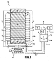
- FIG. 1 schematically a mattress 10 comprising sixteen compartments consisting of flanges 11 arranged transversely to the longitudinal direction of the mattress.
- FIG. 1 there is shown an air supply / exhaust system of the different compartments from a manifold comprising a feed manifold M 1 comprising three feed solenoid valves 13 1 V 1 , V 2 , V 3 and a manifold discharge pipe M 2 comprising three evacuation solenoid valves 13 2 V 4 , V 5 and V 6 .
- This collector is combined with a not shown electronic control unit.
- the supply manifold M 1 is connected to a single pump / compressor C 1 .
- Each supply valve V 1 to V 3 is connected to a main supply pipe t 1 to t 3 feeding a compartment zone Z 1 to Z 3 .
- each drain valve V 4 to V 6 is connected to a main drain pipe t 4 to t 6 .
- the solenoid valve V 1 feeds, from the main supply pipe t 1 , the three compartments of the foot zone, the pipe t 1 comprising two T-fittings, from each of which a secondary pipe bypass t ' 1 ensures the connection via a tubular connecting piece to a tubular supply port 12 1 of each compartment.
- tubular discharge holes 12 2 of said compartments are connected by tubular tips type "fluted", secondary discharge pipes t ' 4 , themselves connected by T-connections to the same main drain pipe t 4 connected to the exhaust solenoid valve V 4 of the exhaust manifold M 2 .
- the solenoid valves V 2 and V 5 provide control of the supply and, respectively, the evacuation of the twelve compartments of the zone of the body, via a main supply pipe t 2 and a main pipe of drain 5 connected to the supply solenoid valves V 2 and, respectively, to the outlet solenoid valves V 5 of the collector.
- the supply ports 12 1 of the twelve compartments of the zone Z 2 of the body are connected to the main supply pipe t 2 via secondary supply pipes t ' 2 , connected by connections T to the pipe t 2 and unrepresented tubular ends to the tubular supply orifices 12 1 .
- secondary drainage pipes t 5 provide the connection between the tubular discharge holes 12 2 to which they are connected by unrepresented tubular ends at one end and, at the other end, to the main pipe. evacuation t 5 using the fitting T.
- the supply V 3 and exhaust solenoid valves V 6 provide the power control, respectively the discharge of the single compartment of the top region via a main feed pipe t 3 and a main drain pipe t 6 to which they are respectively connected.
- This pneumatic connection network between the manifolds and the different compartments of the mattress on the figure 1 operates in said continuous pressure mode because all the compartments of each zone are fed and / or evacuated identically, the only possible modulation being between the different zones from the three pairs of solenoid valves of supply / solenoid valves of evacuation .
- FIG. 1 a pneumatic-controlled CPR-type rapid deflation valve is shown according to the invention 1.
- a pneumatic control valve and energy reserve comprising three said intake ports and three said discharge ports, each of said intake ports 2 being connected to a pipe 15 bypassing the discharge pipes t 4 , t 5 and t 6 of the three zones Z 1 , Z 2 and respectively Z 3 comprising compartments 11 at different pressures.
- Said intake orifices 2 of the valve have a diameter substantially identical to the diameter of the standard discharge tubes 15 and t 4 , t 5 and t 6 .
- Said depressurization port 7 cooperates with a pipe 2 at the other end of which is mounted a purge valve 7 1 which allows, by mechanical opening, to depressurize the pressurizing chamber, if necessary.
- This drain cock July 1 connected to the valve 1 by a tube 7 2 that can be several meters, and can be positioned at the most accessible place for medical staff, to clear the air compartments of the different zones of the mattress opening said purge valve, as will be explained below.
- FIG. 2B there is shown a variant in which the closing / opening means of the depressurization orifice 7 is constituted by a mini solenoid valve (not shown), which can be remotely controlled by electrical activation in a manner known to those skilled in the art. 'art.
- Said first driving body 1a defining said pressurizing chamber 5 has an open face which edge of the cylindrical peripheral wall 5 2 cooperates with the peripheral edge of the diaphragm 4 in the form of a washer, made of elastic plastic material, of rubber type 1 to 2 mm thick with low remanence.
- a diaphragm of elastic material shaped rubber washer 4 is interposed between said first control body 1a and a second circulation body 1b circular section. Said second body 1b is able to be fixed against said first body 1a by means of screws 9 cooperating in peripheral cylindrical perforations 9 1 , which coincide in each of said first and second bodies 1a and 1b.
- first and second bodies 1a and 1b must have surfaces 2 and 8 3 of contact with each other, perfectly ground so as to press the edges of the diaphragm 4 against the peripheral surface 5 2 and 8 3 , each of said first and second bodies, this to ensure a perfect seal.
- the crushing of the periphery of the diaphragm between the first and the second body is provided by the screws 9 passing through the cylindrical perforations 9 1 distributed so as to distribute the force without twisting said body and the diaphragm.
- the surface 8 1 of said second body 1b turned on the side of the first body 1a has a concave shape in the shape of a spherical cap defining the circulation chamber 8 between said concave surface 8 1 and said diaphragm 4.
- the concave surface 8 1 of the second circulation body 1b comprises three so-called inlet orifices 2 with circular cross-section and three so-called evacuation orifices 3 arranged alternately and in a ring with respect to the intake orifices 2.
- the solid surface of said concave surface 8 1 represents more than 50% of the perforated surfaces corresponding to said intake orifice 2 and discharge orifice 3.
- the inlet ports 2 have a diameter of 4 to 8 mm and the distance between an inlet port and each of the adjacent discharge ports is greater than the diameter of said inlet port.
- the cross-sectional area of the cylindrical discharge ports 3 is greater than the circular section of the cylindrical inlet ports 2.
- the hemispherical shape of the internal concave surface 8 1 ( Figure 2C ) of said second body 1b allows the diaphragm 4, when deformed by pressurizing the pressurizing chamber 5, to be pressed on all said concave surface 8 1 and, thus, to seal both said intake ports 2 and 3 discharge ports of the valve.
- the discharge orifices 3 have a non-circular section because they open directly to the air on the face 8 2 of said second circulation body 1b opposite the face 8 1 having a hemispherical concave face delimiting said circulation chamber 8.
- the shape of the hemispherical concave surface 8 1 of said second body 1b, the size, the shape and the distribution of said inlet 2 and outlet 3 orifice make it possible to obtain the best air flow possible, while preserving a surface contacting the diaphragm 4 on the concave surface of the body 1b ensuring a perfect seal of the pressurizing chamber 5 by a perfect closure of said inlet port 2 and discharge ports 3.
- the depth of said hemispherical concave surface corresponds substantially to 1/6 th of the diameter of the diaphragm 4, so that when said diaphragm is in the rest position as shown in FIG. Figure 2A , the cross section at any point inside the circulation chamber 8 is greater than the cumulative area of the inlet port sections 2, the latter being furthermore less than or equal to the cumulative surface area of the ports orifices. evacuation 3.
- the dimensions of the body 1b are determined by the number and the diameters of the intake orifices 2 and the discharge orifices 3 of the valve.
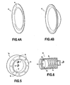
- the diaphragm comprises a peripheral rib 4 1 which facilitates the return, in the rest position of the washer ( Figure 4A ) after deformation according to Figure 4B .
- This non-return valve 6 1 has a cylindrical hollow body 6 4 including a piston 6 5 pressed against an O-ring 6 6 by the action of expansion of a spring 6 3 ensuring closure of the valve and therefore of the orifice 6.
- This cylindrical hollow body 6 4 has longitudinal grooves on its inner surface, able to let air in spite of the piston 6 5 when it is no longer pushed by the spring 6 3 against the O-ring 6 6 .
- the air 6 7 from a mini compressor 6 2 pushes the piston 6 5 , which compresses the spring 6 3 and releases the piston 6 5 of the O-ring 6 6 , which thus allows the passage of air through said body 6 4 along the longitudinal grooves on the surface internal body 6 4 (not shown) to exit at 6 8 inside said pressurizing port 6 towards the pressurizing chamber 5.
- the air coming from the mini compressor 6 2 is sent at a pressure of 100 to 500 mbar, so as to push the piston 6 5 and through the hollow cylindrical body 6 4 to exit into said pressurizing chamber 5 to push the diaphragm 4.
- the mechanical opening valve 7 1 serving as closing / opening means of said depressurization orifice 7 is manually opened, which has the effect of placing the chamber of pressurization 5 at atmospheric pressure, so that the diaphragm 4 which, on its opposite side of the side of the circulation chamber 8, is subjected to a pressure corresponding to the internal inflation pressure of the compartments 11 communicating with the various orifices of admission 2, is deformed until returning to a said right rest position, as shown in FIG. Figure 2A .
- the air contained in the compartments 11 can flow from said inlet ports 2 which are now open, then pass inside said circulation chamber 8 and exit through said discharge openings 3 opening to the outdoors.
- valve "CPR”, according to the invention therefore allows a large discharge rate of the air contained in the flanges 11 and the triggering said "open state" of the valve in which the diaphragm is released from said orifices.
- intake 2 and discharge port 3 to adopt the rest position Figure 2A is triggered without any power supply, by the sole reserve of energy that it contains in pneumatic form.
- the diaphragm has a diameter of 30 millimeters which moves along its axis XX over a displacement distance of 4 to 5 millimeters.
- a volume of pressurization chamber 5 is provided which is large enough to dampen any small leaks at the diaphragm contact / first pilot body 1a and second circulation body 1b.
- the volume of the pressurizing chamber 5 will be at least 5 cm 3 , preferably at least 10 cm 3 , more preferably at least 50 cm 3 , or at least twice the volume between the diaphragms at rest. and the inner surface hemispherical concave of said body 1b delimiting the circulation chamber 8, preferably at least four times, more preferably at least 10 times.
- the diaphragm is made of an elastic synthetic material, such as a bicycle inner tube rubber, having a thickness of at least 0.5 millimeters.
- the other parts of the valve are made of rigid plastic material.
- This type of mini solenoid valve known to those skilled in the art, has the advantage of using electrical energy only for their change of state between an open position allowing the flow of air through the solenoid valve and a closed position preventing the flow of air to said mini solenoid valve and thus through said orifice in question.
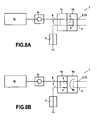
- an energy-saving pneumatic valve according to the present invention as a supply valve 13 1 or a discharge valve 13 2 , in the distribution block manifold 14 for feeding / exhausting the various compartments 11 of the mattress, as shown on the figure 1 .
- valves comprising a single inlet orifice 2 and a single outlet orifice 3.
- the inlet port 2 will be in communication with the main compressor supply Ci whereas the discharge port will lead to the pipes t 1 , t 2 or t 3 respectively for each of the valves supplying compartments areas Z 1 , Z 2 and Z 3 can be inflated to different pressures.
- the exhaust valves 13 2 , V 4 , V 5 and V 6 may also consist of pneumatically operated valves 1 according to the invention having a single outlet opening 3 opening to the air on the side of the block manifold M 2 and a single inlet opening 2 opening on said discharge pipes t 4 , t 5 and t 6 respectively for each of the valves V 4 , V 5 and V 6 receiving the air compartments Z 1 zones, Z 2 and Z 3 .
- the pneumatically actuated valves 13 1 in said open state will allow inflation of said compartments 11 by injecting air from the compressor Ci.
- the injection of air into the inlet orifice 2 is stopped.
- the diaphragm 4 deforms and presses against said inlet orifice 2 and discharge orifice 3, in that the internal pressure inside the pressurizing chamber 5 is kept higher than the pressure applied on the opposite face of the diaphragm, namely the internal pressure of said compartments 11, which communicate with the hollow body 1b via the outlet openings 3.
- the pneumatic control valve 13 1 is thus in a state of shutter.
- said pneumatically actuated discharge valves V 4 to V 6 are in said shut-off state when their pressurizing chamber is at a pressure greater than the internal pressure at the internal pressure of the compartments 11 which communicates with said orifices. admission 2.
- the pneumatic control valves and energy reserve 1 according to the present invention as described above, require energy only for pressurizing said pressurizing chamber 5 for a short time.
- This chamber 5 being only 5 cm 3, a mini compressor 6 2 with a power of 1.4 W and a flow rate of 300 cm 3 / minute running for less than one second and sufficient to bring the pressure to inside the room at a value of 500 mbar.
- valve CPR is shown before commissioning: the non-return valve 6 1 is in the closed position, the diaphragm 5 is in the rest position and the drain valve 7 1 is in the closed position.
Landscapes
- Engineering & Computer Science (AREA)
- General Engineering & Computer Science (AREA)
- Mechanical Engineering (AREA)
- Massaging Devices (AREA)
- Mattresses And Other Support Structures For Chairs And Beds (AREA)
- Invalid Beds And Related Equipment (AREA)
- Fluid-Pressure Circuits (AREA)
Claims (17)
- Pneumatisch gesteuertes Ventil mit Energiereserve (1), mit wenigstens einer Gaseinlaßöffnung (2) und wenigstens einer Öffnung zum Ablassen des Gases (3) durch Entlüftung, wobei die pneumatische Steuerung ermöglicht, folgendes zu steuern, nämlich entweder einen Zustand zum Schließen des Ventils, wodurch die Gaszirkulation zwischen der Einlaßöffnung (2) und der Ablaßöffnung (3) unterbunden wird, oder einen Zustand zum Öffnen des Ventils, wodurch die Gaszirkulation durch die und zwischen den Einlaß- (2) und Ablaßöffnungen (3) in geöffneter Stellung zugelassen wird,- wobei die pneumatische Zustandsänderungssteuerung durch Bewegen einer Drossel (4) erfolgt, wobei die Drossel eine dichte Trennung zwischen einerseits den Einlaß- (2) und Ablaßöffnungen (3) und andererseits einer ersten Kammer, sogenannten Druckkammer (5) herstellt, und- wobei die Drossel geeignet ist, sich zwischen den beiden folgenden Öffnungs- und Schließstellungen, die einen Öffnungszustand bzw. einen Schließzustand des Ventils steuern, elastisch zu verformen:■ einer Schließstellung, in der die Druckkammer (5) durch Einleiten von Gas, vorzugsweise Luft, unter Druck gesetzt wird, wobei die Drossel derart elastisch verformt wird, daß sie die Einlaßöffnung (2) und die Ablaßöffnung (3) verschließt, und■ einer Öffnungsstellung, in der die Druckkammer (5) druckentlastet ist, wobei die Drossel in ihre Ruhestellung zurückkehrt, in der die Drossel die erste Kammer (5) und eine zweite Kammer, sogenannte Zirkulationskammer (8), trennt, wodurch die Gaszirkulation durch die und zwischen den Einlaß- (2) und Ablaßöffnungen (3) innerhalb des Ventils zugelassen wird,wobei das Ventil dadurch gekennzeichnet ist, daß die Druckkammer (5) folgendes umfaßt, nämlich eine Druckbeaufschlagungsöffnung (6), die mit einem ersten Mittel zum Schließen/Öffnen der Druckbeaufschlagungsöffnung (61) und einem Verdichter (62) zusammenwirkt, der geeignet ist, ein Gas, vorzugsweise Luft, unter Druck in die Druckbeaufschlagungsöffnung (6) einzuleiten, sowie eine Öffnung zur Druckentlastung (7) der ersten Kammer (5) durch Bringen auf atmosphärischen Druck, welche mit einem zweiten Mittel zum Schließen/Öffnen der Druckentlastungsöffnung (71) zusammenwirkt,- wobei die Drossel geeignet ist:- in einer Position zum Schließen des Ventils, ohne Einleiten von Gas in die Druckbeaufschlagungsöffnung zu bleiben, wenn der Druck der Druckkammer höher als der Druck der Zirkulationskammer (8) ist und das erste und das zweite Mittel zum Schließen/Öffnen der Öffnungen (6, 7) in der geschlossenen Position bleiben, und- von einer Schließposition in eine Position zum Öffnen des Ventils überzugehen und in einer Position zum Öffnen des Ventils zu bleiben, wenn das zweite Mittel zum Schließen/Öffnen der Druckentlastungsöffnung geöffnet ist, und- von einer Öffnungsposition in eine Position zum Schließen des Ventils überzugehen, und zwar durch Schließen des zweiten Mittels zum Schließen/Öffnen der Druckentlastungsöffnung und Öffnen des ersten Mittels zum Schließen/Öffnen der Druckbeaufschlagungsöffnung, anschließend durch Einleiten von Gas in die Druckbeaufschlagungsöffnung bis der Druck der Druckkammer (5) höher als der Druck der Zirkulationskammer (8) ist.
- Pneumatisch gesteuertes Ventil mit Energiereserve (1) nach Anspruch 1, dadurch gekennzeichnet, daß das erste Mittel zum Schließen/Öffnen (61) der Druckbeaufschlagungsöffnung (6) ein Rückschlagventil mit automatischer Funktionsweise, das ohne weitere äußere Energiezufuhr als den Druck des in die Druckbeaufschlagungsöffnung eingeleiteten Gases funktioniert, vorzugsweise ein mechanisches Rückschlagventil ist, das ein Federmittel (63), wie eine Feder umfaßt, wobei das Ventil, vorzugsweise das Federmittel geeignet ist:- das erste Mittel zum Schließen/Öffnen der Druckbeaufschlagungsöffnung (61) in der Öffnungsstellung zu halten, solange der Druck der Druckkammer geringer als der oder gleich dem Druck der Zirkulationskammer (8) ist, und- das erste Mittel zum Schließen/Öffnen der Druckbeaufschlagungsöffnung (61) in der Schließstellung zu halten, solange keine Druckluft unter einem Druck oberhalb des Drucks der Luft in der Druckkammer (5) eingeleitet wird.
- Pneumatisch gesteuertes Ventil mit Energiereserve (1) nach einem der Ansprüche 1 oder 2, dadurch gekennzeichnet, daß das zweite Mittel zum Schließen/Öffnen (71) der Druckentlastungsöffnung (7) ein Ablaßhahn mit manueller mechanischer Steuerung ist, der mit der Druckentlastungsöffnung zusammenwirkt, vorzugsweise am Ende eines Schlauchs (72), der die Verbindung zwischen dem Ablaßhahn (71) und der Druckentlastungsöffnung (7) sicherstellt.
- Pneumatisch gesteuertes Ventil mit Energiereserve (1) nach einem der Ansprüche 1 bis 3, dadurch gekennzeichnet, daß:- es einen ersten Körper (1a), sogenannten Steuerkörper, und einen zweiten Körper (1 b), sogenannten Zirkulationskörper umfaßt, wobei die Drossel (4) zwischen den beiden ersten und zweiten Körpern eingefügt und an ihrem Umfang festgelegt ist,- wobei der erste Körper (1a) eine Hohlform aufweist, die einen Teil der Wand der Druckkammer (5) begrenzt, wobei der erste Körper von der Druckbeaufschlagungsöffnung (6) und der Druckentlastungsöffnung (7) durchbohrt ist, und- wobei der zweite Zirkulationskörper (1b) eine konkav geformte Fläche (81) aufweist, die der Drossel innerhalb des Ventils zugewandt ist, und wobei der zweite Körper von der Einlaßöffnung (2) und der Ablaßöffnung (3) durchbohrt ist.
- Pneumatisch gesteuertes Ventil mit Energiereserve (1) nach einem der Ansprüche 1 bis 4, dadurch gekennzeichnet, daß wenn die Drossel in der Öffnungsstellung ist, die Fläche des minimalen Durchlaßquerschnitts zwischen der Einlaßöffnung (2) und der Ablaßöffnung (3) innerhalb der Zirkulationskammer wenigstens gleich der kumulierten Fläche der Querschnitte der Einlaßöffnungen ist, wobei diese selbst kleiner als die oder gleich der kumulierten Fläche der Querschnitte der Ablaßöffnungen ist.
- Pneumatisch gesteuertes Ventil mit Energiereserve (1) nach einem der Ansprüche 1 bis 5, dadurch gekennzeichnet, daß die verschiedenen Einlaß- (2) und Ablaßöffnungen (3) durch die volle Fläche der konkaven Fläche voneinander getrennt sind und der Abstand zwischen zwei am nächsten gelegenen Öffnungen wenigstens gleich der Hälfte des Durchmessers der größten Einlaß- und/oder Ablaßöffnung ist.
- Pneumatisch gesteuertes Ventil mit Energiereserve (1) nach einem der Ansprüche 1 bis 6, dadurch gekennzeichnet, daß die Einlaßöffnung (2) und die Ablaßöffnung (3) vorzugsweise zylindrische Öffnungen sind, die in die konkave, vorzugsweise eine teilkugelkappenförmige Fläche bildende Fläche (81) münden, und die Einlaß- (2) und Ablaßöffnungen (3) des Ventils kranzförmig und abwechselnd, zur Symmetrieachse der konkaven Fläche symmetrisch angeordnet sind.
- Pneumatisch gesteuertes Ventil mit Energiereserve (1) nach einem der Ansprüche 1 bis 7, dadurch gekennzeichnet, daß die Drossel aus elastischem Kunststoff, vorzugsweise aus Gummi, mit einer Dicke kleiner oder gleich 2 Millimeter gefertigt worden ist.
- Pneumatisch gesteuertes Ventil mit Energiereserve (1) nach einem der Ansprüche 1 bis 8, dadurch gekennzeichnet, daß es eine Vielzahl von, vorzugsweise wenigstens drei Einlaßöffnungen (2) sowie eine Vielzahl von, weiterhin vorzugsweise wenigstens drei Ablaßöffnungen (3) umfaßt.
- Pneumatisch gesteuertes Ventil mit Energiereserve (1) nach einem der Ansprüche 1 bis 8, dadurch gekennzeichnet, daß es folgendes umfaßt:- eine einzige Einlaßöffnung (2) und- eine einzige Ablaßöffnung (3).
- Pneumatisch gesteuertes Ventil mit Energiereserve (1) nach Anspruch 10, dadurch gekennzeichnet, daß:- das erste Mittel zum Schließen/Öffnen der Druckbeaufschlagungsöffnung (61) ein ohne Energiezufuhr mechanisch funktionierendes Rückschlagventil ist, wie es in Anspruch 3 definiert ist, oder ein Mini-Elektroventil, das mit der Druckbeaufschlagungsöffnung (6) zusammenwirkt, und- das zweite Mittel zum Schließen/Öffnen der Druckentlastungsöffnung (71) ein Mini-Elektroventil ist, das mit der Druckentlastungsöffnung zusammenwirkt.
- Stützvorrichtung, insbesondere für den Körper eines Menschen, vom Typ Matratze (10), mit einer Vielzahl von n Zellen (11), vorzugsweise wenigstens drei Zellen, weiterhin vorzugsweise drei bis vierundzwanzig Zellen, die geeignet sind, mit einem Fluid, insbesondere einem Gas, weiterhin insbesondere mit Luft aufgeblasen zu werden, wobei die Zellen jeweils wenigstens eine Versorgungsöffnung (121) und eine Fluidablaßöffnung (122) aufweisen, sowie mit wenigstens einem Versorgungsventil (131), das ermöglicht, die Fluidversorgung der Zellen zu steuern, und wenigstens einem Ablaßventil (132), das ermöglicht, das Fluid aus den Zellen abzulassen, wobei jedes Versorgungsventil mit wenigstens einer Zellenversorgungsöffnung und jedes Ablaßventil mit wenigstens einer Zellenentleerungsöffnung zusammenwirkt, dadurch gekennzeichnet, daß sie wenigstens ein pneumatisch gesteuertes Ventil mit Energie-Reserve (1) nach einem der Ansprüche 1 bis 11 aufweist.
- Stützvorrichtung nach Anspruch 12, dadurch gekennzeichnet, daß sie wenigstens ein Ventil nach Anspruch 9 als Ventil zum vollständigen und schnellen Entleeren, sogenanntes CPR-Ventil, aufweist, von dem:- jede Einlaßöffnung (2) mit Ablaßöffnungen (122) der Zellen (11) eines gleichen Bereichs verbunden ist, in denen die unterschiedlichen Zellen (11) auf den gleichen Druck aufgeblasen sind, wobei die unterschiedlichen Einlaßöffnungen (2) mit Öffnungen zum Entleeren der Zellen (122) bzw. Entleerungsschläuchen (t4-t6) unterschiedlicher Bereiche (z1), (z2), (z3) verbunden sind, in denen die Gasversorgungs- und Gasablaßvorgänge der Zellen über unterschiedliche Versorgungsventile (131) und Ablaßventile (132) gesteuert werden, und- jede Ablaßöffnung (3) des pneumatisch gesteuerten Ventils mit der Außenluft in Verbindung steht, wenn das pneumatisch gesteuerte Ventil sich im Öffnungszustand befindet.
- Stützvorrichtung nach Anspruch 13, dadurch gekennzeichnet, daß die Einlaßöffnungen (2) des pneumatisch gesteuerten Ventils mit Energie-Reserve (1) mit Entleerungsschläuchen (t4-t6) zwischen den Zellenentleerungsöffnungen (122) und den Ablaßventilen (132) verbunden sind, wobei letztere vorzugsweise in einem Verteilerblock (14) untergebrachte Elektroventile sind.
- Vorrichtung nach Anspruch 12, dadurch gekennzeichnet, daß sie wenigstens ein pneumatisch gesteuertes Ventil nach Anspruch 10 oder 11 mit einer einzigen Einlaßöffnung (2) und einer einzigen Ablaßöffnung (3) aufweist, bestehend aus:- einem Ventil, das als Ventil zur Versorgung (131) wenigstens einer Zelle (11) dient, wobei die Einlaßöffnung (2) des Ventils mit einem Hauptverdichter zum Einleiten von Druckluft verbunden ist und seine Ablaßöffnung (3) mit wenigstens einer Zellenversorgungsöffnung (121) oder einem Versorgungsschlauch (t1-t3), der mit wenigstens einer Versorgungsöffnung wenigstens einer Zelle zusammenwirkt, verbunden ist, und/oder- einem Ventil, das als Luftablaßventil (132) der Zellen (11) dient, wobei die Einlaßöffnung (2) des pneumatischen Ventils über einen Schlauch (t4-t6) mit wenigstens einer Ablaßöffnung (122) wenigstens einer Zelle (11) verbunden ist, wobei die Ablaßöffnung (3) des pneumatisch gesteuerten Ventils mit der Außenluft in Verbindung steht.
- Verfahren zur Verwendung einer Stützvorrichtung nach einem der Ansprüche 12 bis 15, dadurch gekennzeichnet, daß:- für das Erzielen einer Schließstellung des Ventils Druckluft über die Druckbeaufschlagungsöffnung in eine Druckkammer geleitet wird, wobei das erste Schließ-/Öffnungsmittel (61) der Druckbeaufschlagungsöffnung sich in der Öffnungsstellung befindet, während das zweite Schließ-/Öffnungsmittel der Druckentlastungsöffnung sich in der Schließstellung befindet, bis der Druck der Druckkammer (5) höher als der Druck der Zirkulationskammer (8) ist, so daß die Drossel verformt wird, um die Einlaßöffnung und Ablaßöffnung (3) zu verschließen, und- für das Erzielen einer Öffnungsstellung des Ventils das Entleeren der Druckkammer durch Öffnen des zweiten Schließ-/Öffnungsmittels der Druckentlastungsöffnung (7) vollzogen wird, so daß die Drossel in ihre Ruhestellung zurückkehrt, in der die Drossel die erste Druckkammer (5) und die zweite Zirkulationskammer trennt, wodurch die Gaszirkulation zwischen der Einlaßöffnung (2) und der Ablaßöffnung (3) zugelassen wird.
- Verfahren nach Anspruch 16, zur Verwendung einer Stützvorrichtung vom Typ Matratze, wobei ein pneumatisch gesteuertes Ventil als Ventil zum vollständigen und schnellen Entleeren vom Typ CPR-Ventil dient, wie es in einem der Ansprüche 13 oder 14 definiert ist, dadurch gekennzeichnet, daß:- für das Erzielen einer Schließstellung des pneumatisch gesteuerten Ventils mit Energie-Reserve (1) vom Typ CPR-Ventil Druckluft in eine Druckkammer geleitet wird, bis der Druck in der Druckkammer über dem Maximaldruck in den Zellen liegt, vorzugsweise zwischen 100 und 500 mbar beträgt, und- zum Erzielen eines vollständigen und schnellen Entleerens aller Zellen der Matratze das pneumatisch gesteuerte Ventil mit Energie-Reserve (1) vom Typ CPR-Ventil in die Öffnungsstellung gebracht wird.
Applications Claiming Priority (1)
| Application Number | Priority Date | Filing Date | Title |
|---|---|---|---|
| FR0703742A FR2916512B1 (fr) | 2007-05-25 | 2007-05-25 | "vanne a commande pneumatique et reserve d'energie et dispositif de support,de type matelas, en comprenant |
Publications (2)
| Publication Number | Publication Date |
|---|---|
| EP1995502A1 EP1995502A1 (de) | 2008-11-26 |
| EP1995502B1 true EP1995502B1 (de) | 2010-08-04 |
Family
ID=38988328
Family Applications (1)
| Application Number | Title | Priority Date | Filing Date |
|---|---|---|---|
| EP20080156661 Ceased EP1995502B1 (de) | 2007-05-25 | 2008-05-21 | Pneumatisches Regelventil und Energiespeicher und Stützvorrichtung |
Country Status (4)
| Country | Link |
|---|---|
| US (1) | US7685662B2 (de) |
| EP (1) | EP1995502B1 (de) |
| DE (1) | DE602008002013D1 (de) |
| FR (1) | FR2916512B1 (de) |
Families Citing this family (8)
| Publication number | Priority date | Publication date | Assignee | Title |
|---|---|---|---|---|
| US8856992B2 (en) * | 2010-02-05 | 2014-10-14 | Stryker Corporation | Patient/invalid handling support |
| TW201204968A (en) * | 2010-07-23 | 2012-02-01 | Shang-Neng Wu | Control valve structure of air cushion bed |
| US10368796B2 (en) | 2011-07-22 | 2019-08-06 | Tc13-Pressure Applications Llc | Systems and methods for monitoring and providing therapeutic support for a user |
| US9277829B2 (en) | 2011-07-22 | 2016-03-08 | TC13—Pressure Applications LLC | Systems and methods for monitoring and providing therapeutic support for a user |
| US9890031B2 (en) * | 2015-09-17 | 2018-02-13 | LJ Crafted Wines | Alcoholic beverage barrel dispensing apparatus |
| US12150905B2 (en) | 2018-11-27 | 2024-11-26 | Stryker Corporation | Patient support apparatus with notification system |
| CN117617703A (zh) * | 2023-11-14 | 2024-03-01 | 宁波雪狼户外用品科技有限公司 | 一种充气床垫 |
| CN117838958B (zh) * | 2024-03-07 | 2024-05-31 | 北京大学第一医院(北京大学第一临床医学院) | 一种贴身尿袋 |
Family Cites Families (25)
| Publication number | Priority date | Publication date | Assignee | Title |
|---|---|---|---|---|
| FR1375258A (fr) * | 1963-09-06 | 1964-10-16 | Dubix Sa Ets | Vanne à membrane plastique |
| US3633605A (en) * | 1969-03-18 | 1972-01-11 | Robertshaw Controls Co | Pneumatic control system and pneumatic control device therefor or the like |
| US4068334A (en) * | 1976-06-04 | 1978-01-17 | Harry E. Grover | Inflatable body support apparatus |
| GB2070174A (en) * | 1980-02-26 | 1981-09-03 | Watkins & Watson Ltd | Conduit connector |
| US4838309A (en) | 1985-12-30 | 1989-06-13 | Ssi Medical Services, Inc. | Variable flow gas valve |
| US4745647A (en) | 1985-12-30 | 1988-05-24 | Ssi Medical Services, Inc. | Patient support structure |
| US5051673A (en) * | 1985-12-30 | 1991-09-24 | Goodwin Vernon L | Patient support structure |
| US5802640A (en) | 1992-04-03 | 1998-09-08 | Hill-Rom, Inc. | Patient care system |
| GB8901594D0 (en) | 1989-01-25 | 1989-03-15 | Mediscus Prod Ltd | Valve design |
| US5606754A (en) | 1989-03-09 | 1997-03-04 | Ssi Medical Services, Inc. | Vibratory patient support system |
| US5052067A (en) | 1989-03-09 | 1991-10-01 | Ssi Medical Services, Inc. | Bimodal system for pressurizing a low air loss patient support |
| CH686051A5 (de) * | 1991-03-26 | 1995-12-15 | Galipag | Regelorgan fur eine Rohrleitung. |
| US5349983A (en) | 1993-07-07 | 1994-09-27 | Ssi Medical Services, Inc. | Proportional control valve for patient support system |
| FR2718347B1 (fr) | 1994-04-06 | 1996-06-28 | Support Systems International | Procédé et appareil de support d'un élément à supporter, en particulier le corps d'un patient permettant un support à une profondeur d'enfoncement contrôlée. |
| JP3355254B2 (ja) * | 1994-09-26 | 2002-12-09 | エヌオーケー株式会社 | ダイアフラムバルブ |
| US5647079A (en) | 1996-03-20 | 1997-07-15 | Hill-Rom, Inc. | Inflatable patient support surface system |
| US5941272A (en) * | 1996-12-04 | 1999-08-24 | Imaginair, Inc. | Three way universal valve |
| US6202672B1 (en) | 1997-08-25 | 2001-03-20 | Hill-Rom, Inc. | Valve assembly |
| US6073289A (en) | 1997-12-18 | 2000-06-13 | Hill-Rom, Inc. | Air fluidized bed |
| CA2355964C (en) | 1999-01-08 | 2006-04-04 | Hill-Rom, Inc. | Mattress assembly |
| JP2006506212A (ja) * | 2002-11-18 | 2006-02-23 | チャフィー,ロバート,ビー. | 膨張式デバイス |
| DE10337370B4 (de) * | 2003-08-07 | 2005-07-21 | Visteon Global Technologies, Inc., Dearborn | Sicherheitsabsperreinrichtung |
| US7322801B2 (en) * | 2003-08-26 | 2008-01-29 | Thomas Industries Inc. | Compact linear air pump and valve package |
| JP2005155712A (ja) * | 2003-11-21 | 2005-06-16 | Mitsubishi Electric Corp | 電磁弁 |
| FR2912884B1 (fr) * | 2007-02-27 | 2012-09-28 | Hill Rom Ind Sa | "dispositif de support de type matelas comprenant au moins une electrovanne permettant de commander l'alimentation/evacuation de fluide dans des compartiments du matelas" |
-
2007
- 2007-05-25 FR FR0703742A patent/FR2916512B1/fr not_active Expired - Fee Related
-
2008
- 2008-05-21 EP EP20080156661 patent/EP1995502B1/de not_active Ceased
- 2008-05-21 DE DE200860002013 patent/DE602008002013D1/de active Active
- 2008-05-22 US US12/125,402 patent/US7685662B2/en not_active Expired - Fee Related
Also Published As
| Publication number | Publication date |
|---|---|
| US7685662B2 (en) | 2010-03-30 |
| FR2916512A1 (fr) | 2008-11-28 |
| DE602008002013D1 (de) | 2010-09-16 |
| FR2916512B1 (fr) | 2013-03-15 |
| US20080289114A1 (en) | 2008-11-27 |
| EP1995502A1 (de) | 2008-11-26 |
Similar Documents
| Publication | Publication Date | Title |
|---|---|---|
| EP1995502B1 (de) | Pneumatisches Regelventil und Energiespeicher und Stützvorrichtung | |
| EP1964494A1 (de) | Unterlagevorrichtung vom Typ Matratze, die mindestens ein Magnetventil zur Steuerung der Befüllung mit/Entleerung von Flüssigkeit der Matratzenabschnitte umfasst | |
| FR2922427A1 (fr) | Cellule gonflable, procede de fabrication et dispositif de support en comportant | |
| CA2421719C (fr) | Procede et dispositif de commande du gonflement d'une enveloppe prothetique | |
| EP0973425B1 (de) | Verfahren und gerät zum schnellen entleeren einer luftkammer, insbesondere für eine körperstütze wie eine matratze | |
| EP1893141B1 (de) | Intragastrischer Ballon mit doppeltem Membranventil und dazugehöriges Einsetzungskit | |
| EP2922447B1 (de) | Vorrichtung zum zubereiten von getränken durch behälterinfusion mit einer schwenkwiege | |
| EP2050425B1 (de) | Verfahren zum abwechselnden Aufblasen einer Halterungsvorrichtung, bestehend aus aufblasbaren Zellen, und Vorrichtung zu dessen Umsetzung | |
| EP2005929B1 (de) | Matratze mit heterogener aufblasbarer Struktur | |
| EP2205306A1 (de) | Vorrichtung zum aufblasen eines chirurgischen implantats | |
| FR2560041A1 (fr) | Dispositif formant matelas d'air | |
| EP3285654B1 (de) | Verfahren zur probenentnahme von mikroorganismen, vorrichtung zur probenentnahme von mikroorganismen und kit mit solcher vorrichtung | |
| EP0495902A1 (de) | Starre umhüllende schale mit dichtem innenvolumen. | |
| EP2861275B1 (de) | Vorrichtung zur injektion eines flüssigprodukts mit zwei gegeneinander drehbaren halbschalen | |
| FR2949320A1 (fr) | Dispositif de basculement lateral | |
| EP2120654A2 (de) | Verfahren zur herstellung einer infusion | |
| CA3085667A1 (fr) | Dispositif medical pour la conservation d'un tissu corneen incluant un couvercle d'applanation, et eventuellement un couvercle de trepanation | |
| EP0729733B1 (de) | Aufblasbarer Beutel, insbesondere für künstlichen After | |
| FR3074997A1 (fr) | Dispositif medical sous forme de cassette pour la conservation et/ou le controle qualite et/ou le traitement d'un prelevement corneen | |
| EP1189806B1 (de) | Unabhängiges unterwasser- atemgerät mit integrierter, manueller befüllung | |
| EP0302767B1 (de) | Vorrichtung zum Massieren des Körpers durch zyklische Druckeinwirkung | |
| EP3934484A1 (de) | Matratzenvorrichtung mit modularer, statischer oder dynamischer dekompression | |
| EP3716898B1 (de) | Okklusionsmanschette und implantierbares okklusionssystem mit solch einer manschette | |
| WO1997003586A2 (fr) | Un dispositif de boisson reutilisable | |
| EP3459507A2 (de) | Formverfahren einer sohle in einem negativabdruck, und vorrichtung und system zum formen einer sohle für dessen umsetzung |
Legal Events
| Date | Code | Title | Description |
|---|---|---|---|
| PUAI | Public reference made under article 153(3) epc to a published international application that has entered the european phase |
Free format text: ORIGINAL CODE: 0009012 |
|
| AK | Designated contracting states |
Kind code of ref document: A1 Designated state(s): AT BE BG CH CY CZ DE DK EE ES FI FR GB GR HR HU IE IS IT LI LT LU LV MC MT NL NO PL PT RO SE SI SK TR |
|
| AX | Request for extension of the european patent |
Extension state: AL BA MK RS |
|
| 17P | Request for examination filed |
Effective date: 20090513 |
|
| AKX | Designation fees paid |
Designated state(s): DE FR GB |
|
| GRAP | Despatch of communication of intention to grant a patent |
Free format text: ORIGINAL CODE: EPIDOSNIGR1 |
|
| GRAS | Grant fee paid |
Free format text: ORIGINAL CODE: EPIDOSNIGR3 |
|
| GRAA | (expected) grant |
Free format text: ORIGINAL CODE: 0009210 |
|
| AK | Designated contracting states |
Kind code of ref document: B1 Designated state(s): DE FR GB |
|
| REG | Reference to a national code |
Ref country code: GB Ref legal event code: FG4D Free format text: NOT ENGLISH |
|
| REF | Corresponds to: |
Ref document number: 602008002013 Country of ref document: DE Date of ref document: 20100916 Kind code of ref document: P |
|
| PLBE | No opposition filed within time limit |
Free format text: ORIGINAL CODE: 0009261 |
|
| STAA | Information on the status of an ep patent application or granted ep patent |
Free format text: STATUS: NO OPPOSITION FILED WITHIN TIME LIMIT |
|
| 26N | No opposition filed |
Effective date: 20110506 |
|
| REG | Reference to a national code |
Ref country code: DE Ref legal event code: R097 Ref document number: 602008002013 Country of ref document: DE Effective date: 20110506 |
|
| REG | Reference to a national code |
Ref country code: FR Ref legal event code: PLFP Year of fee payment: 9 |
|
| REG | Reference to a national code |
Ref country code: FR Ref legal event code: PLFP Year of fee payment: 10 |
|
| REG | Reference to a national code |
Ref country code: FR Ref legal event code: PLFP Year of fee payment: 11 |
|
| PGFP | Annual fee paid to national office [announced via postgrant information from national office to epo] |
Ref country code: GB Payment date: 20220426 Year of fee payment: 15 Ref country code: FR Payment date: 20220421 Year of fee payment: 15 Ref country code: DE Payment date: 20220420 Year of fee payment: 15 |
|
| REG | Reference to a national code |
Ref country code: DE Ref legal event code: R082 Ref document number: 602008002013 Country of ref document: DE Representative=s name: CBDL PATENTANWAELTE GBR, DE |
|
| REG | Reference to a national code |
Ref country code: DE Ref legal event code: R119 Ref document number: 602008002013 Country of ref document: DE |
|
| GBPC | Gb: european patent ceased through non-payment of renewal fee |
Effective date: 20230521 |
|
| PG25 | Lapsed in a contracting state [announced via postgrant information from national office to epo] |
Ref country code: DE Free format text: LAPSE BECAUSE OF NON-PAYMENT OF DUE FEES Effective date: 20231201 Ref country code: GB Free format text: LAPSE BECAUSE OF NON-PAYMENT OF DUE FEES Effective date: 20230521 |
|
| PG25 | Lapsed in a contracting state [announced via postgrant information from national office to epo] |
Ref country code: FR Free format text: LAPSE BECAUSE OF NON-PAYMENT OF DUE FEES Effective date: 20230531 |