EP1995513B1 - Procédé destiné au montage d'une lampe à DEL - Google Patents
Procédé destiné au montage d'une lampe à DEL Download PDFInfo
- Publication number
- EP1995513B1 EP1995513B1 EP08101709.7A EP08101709A EP1995513B1 EP 1995513 B1 EP1995513 B1 EP 1995513B1 EP 08101709 A EP08101709 A EP 08101709A EP 1995513 B1 EP1995513 B1 EP 1995513B1
- Authority
- EP
- European Patent Office
- Prior art keywords
- led module
- optical unit
- led
- relative
- optical
- Prior art date
- Legal status (The legal status is an assumption and is not a legal conclusion. Google has not performed a legal analysis and makes no representation as to the accuracy of the status listed.)
- Active
Links
Images
Classifications
-
- F—MECHANICAL ENGINEERING; LIGHTING; HEATING; WEAPONS; BLASTING
- F21—LIGHTING
- F21V—FUNCTIONAL FEATURES OR DETAILS OF LIGHTING DEVICES OR SYSTEMS THEREOF; STRUCTURAL COMBINATIONS OF LIGHTING DEVICES WITH OTHER ARTICLES, NOT OTHERWISE PROVIDED FOR
- F21V17/00—Fastening of component parts of lighting devices, e.g. shades, globes, refractors, reflectors, filters, screens, grids or protective cages
- F21V17/10—Fastening of component parts of lighting devices, e.g. shades, globes, refractors, reflectors, filters, screens, grids or protective cages characterised by specific fastening means or way of fastening
- F21V17/101—Fastening of component parts of lighting devices, e.g. shades, globes, refractors, reflectors, filters, screens, grids or protective cages characterised by specific fastening means or way of fastening permanently, e.g. welding, gluing or riveting
-
- B—PERFORMING OPERATIONS; TRANSPORTING
- B60—VEHICLES IN GENERAL
- B60Q—ARRANGEMENT OF SIGNALLING OR LIGHTING DEVICES, THE MOUNTING OR SUPPORTING THEREOF OR CIRCUITS THEREFOR, FOR VEHICLES IN GENERAL
- B60Q3/00—Arrangement of lighting devices for vehicle interiors; Lighting devices specially adapted for vehicle interiors
- B60Q3/40—Arrangement of lighting devices for vehicle interiors; Lighting devices specially adapted for vehicle interiors specially adapted for specific vehicle types
- B60Q3/41—Arrangement of lighting devices for vehicle interiors; Lighting devices specially adapted for vehicle interiors specially adapted for specific vehicle types for mass transit vehicles, e.g. buses
- B60Q3/44—Spotlighting, e.g. reading lamps
-
- B—PERFORMING OPERATIONS; TRANSPORTING
- B60—VEHICLES IN GENERAL
- B60Q—ARRANGEMENT OF SIGNALLING OR LIGHTING DEVICES, THE MOUNTING OR SUPPORTING THEREOF OR CIRCUITS THEREFOR, FOR VEHICLES IN GENERAL
- B60Q3/00—Arrangement of lighting devices for vehicle interiors; Lighting devices specially adapted for vehicle interiors
- B60Q3/70—Arrangement of lighting devices for vehicle interiors; Lighting devices specially adapted for vehicle interiors characterised by the purpose
- B60Q3/76—Arrangement of lighting devices for vehicle interiors; Lighting devices specially adapted for vehicle interiors characterised by the purpose for spotlighting, e.g. reading lamps
-
- F—MECHANICAL ENGINEERING; LIGHTING; HEATING; WEAPONS; BLASTING
- F21—LIGHTING
- F21K—NON-ELECTRIC LIGHT SOURCES USING LUMINESCENCE; LIGHT SOURCES USING ELECTROCHEMILUMINESCENCE; LIGHT SOURCES USING CHARGES OF COMBUSTIBLE MATERIAL; LIGHT SOURCES USING SEMICONDUCTOR DEVICES AS LIGHT-GENERATING ELEMENTS; LIGHT SOURCES NOT OTHERWISE PROVIDED FOR
- F21K9/00—Light sources using semiconductor devices as light-generating elements, e.g. using light-emitting diodes [LED] or lasers
-
- F—MECHANICAL ENGINEERING; LIGHTING; HEATING; WEAPONS; BLASTING
- F21—LIGHTING
- F21V—FUNCTIONAL FEATURES OR DETAILS OF LIGHTING DEVICES OR SYSTEMS THEREOF; STRUCTURAL COMBINATIONS OF LIGHTING DEVICES WITH OTHER ARTICLES, NOT OTHERWISE PROVIDED FOR
- F21V7/00—Reflectors for light sources
- F21V7/0066—Reflectors for light sources specially adapted to cooperate with point like light sources; specially adapted to cooperate with light sources the shape of which is unspecified
-
- G—PHYSICS
- G02—OPTICS
- G02B—OPTICAL ELEMENTS, SYSTEMS OR APPARATUS
- G02B27/00—Optical systems or apparatus not provided for by any of the groups G02B1/00 - G02B26/00, G02B30/00
- G02B27/62—Optical apparatus specially adapted for adjusting optical elements during the assembly of optical systems
-
- F—MECHANICAL ENGINEERING; LIGHTING; HEATING; WEAPONS; BLASTING
- F21—LIGHTING
- F21V—FUNCTIONAL FEATURES OR DETAILS OF LIGHTING DEVICES OR SYSTEMS THEREOF; STRUCTURAL COMBINATIONS OF LIGHTING DEVICES WITH OTHER ARTICLES, NOT OTHERWISE PROVIDED FOR
- F21V29/00—Protecting lighting devices from thermal damage; Cooling or heating arrangements specially adapted for lighting devices or systems
- F21V29/50—Cooling arrangements
- F21V29/70—Cooling arrangements characterised by passive heat-dissipating elements, e.g. heat-sinks
-
- F—MECHANICAL ENGINEERING; LIGHTING; HEATING; WEAPONS; BLASTING
- F21—LIGHTING
- F21Y—INDEXING SCHEME ASSOCIATED WITH SUBCLASSES F21K, F21L, F21S and F21V, RELATING TO THE FORM OR THE KIND OF THE LIGHT SOURCES OR OF THE COLOUR OF THE LIGHT EMITTED
- F21Y2115/00—Light-generating elements of semiconductor light sources
- F21Y2115/10—Light-emitting diodes [LED]
-
- Y—GENERAL TAGGING OF NEW TECHNOLOGICAL DEVELOPMENTS; GENERAL TAGGING OF CROSS-SECTIONAL TECHNOLOGIES SPANNING OVER SEVERAL SECTIONS OF THE IPC; TECHNICAL SUBJECTS COVERED BY FORMER USPC CROSS-REFERENCE ART COLLECTIONS [XRACs] AND DIGESTS
- Y10—TECHNICAL SUBJECTS COVERED BY FORMER USPC
- Y10T—TECHNICAL SUBJECTS COVERED BY FORMER US CLASSIFICATION
- Y10T29/00—Metal working
- Y10T29/49—Method of mechanical manufacture
- Y10T29/49002—Electrical device making
- Y10T29/49004—Electrical device making including measuring or testing of device or component part
-
- Y—GENERAL TAGGING OF NEW TECHNOLOGICAL DEVELOPMENTS; GENERAL TAGGING OF CROSS-SECTIONAL TECHNOLOGIES SPANNING OVER SEVERAL SECTIONS OF THE IPC; TECHNICAL SUBJECTS COVERED BY FORMER USPC CROSS-REFERENCE ART COLLECTIONS [XRACs] AND DIGESTS
- Y10—TECHNICAL SUBJECTS COVERED BY FORMER USPC
- Y10T—TECHNICAL SUBJECTS COVERED BY FORMER US CLASSIFICATION
- Y10T29/00—Metal working
- Y10T29/49—Method of mechanical manufacture
- Y10T29/49002—Electrical device making
- Y10T29/49117—Conductor or circuit manufacturing
- Y10T29/49124—On flat or curved insulated base, e.g., printed circuit, etc.
- Y10T29/4913—Assembling to base an electrical component, e.g., capacitor, etc.
-
- Y—GENERAL TAGGING OF NEW TECHNOLOGICAL DEVELOPMENTS; GENERAL TAGGING OF CROSS-SECTIONAL TECHNOLOGIES SPANNING OVER SEVERAL SECTIONS OF THE IPC; TECHNICAL SUBJECTS COVERED BY FORMER USPC CROSS-REFERENCE ART COLLECTIONS [XRACs] AND DIGESTS
- Y10—TECHNICAL SUBJECTS COVERED BY FORMER USPC
- Y10T—TECHNICAL SUBJECTS COVERED BY FORMER US CLASSIFICATION
- Y10T29/00—Metal working
- Y10T29/49—Method of mechanical manufacture
- Y10T29/49002—Electrical device making
- Y10T29/49117—Conductor or circuit manufacturing
- Y10T29/49124—On flat or curved insulated base, e.g., printed circuit, etc.
- Y10T29/4913—Assembling to base an electrical component, e.g., capacitor, etc.
- Y10T29/49133—Assembling to base an electrical component, e.g., capacitor, etc. with component orienting
Definitions
- the invention relates to a method for mounting an LED light, which is a reading or seating light for a vehicle, such as an aircraft, train or a coach, and which is an LED module and a reflective (eg reflector) and / or refractive (eg, lens) optical unit.
- a vehicle such as an aircraft, train or a coach
- an LED module and a reflective (eg reflector) and / or refractive (eg, lens) optical unit.
- luminaires usually includes requirements in terms of brightness, color and light distribution.
- the light fixtures also have optical systems, which include, for example, reflectors and / or lenses.
- the optical systems to achieve a low overall depth of the lamp should be as small as possible.
- LEDs are increasingly used as a light source.
- the dies In many commercially available LEDs, the dies have relatively large positional tolerances, especially in the direction of the optical axis.
- the optical systems used for the luminaires are also subject to tolerances in terms of position, shape and their optical properties, in terms of efficiency, gloss level and image accuracy.
- the object of the invention is to improve the assembly of LED lights to reduce the rejection rate.
- the invention proposes a method for assembling an LED reading or seat luminaire having a LED module and a reflective and / or refractive optical unit for a vehicle, such as a coach, train or an airplane the method has the steps specified in claim 1.
- the LED module and optical unit to achieve a desired light intensity along the optical axis of the LED light are moved relative to each other during assembly of an LED light until a relative position of both components has been found at the required intensity the light is given.
- an LED module which has at least one LED, and an optical unit, which comprises a refractive and / or a reflective element, are arranged along the optical axis of the LED lamp for the purpose of subsequent fixing.
- the LED module is triggered to emit electromagnetic radiation, which serves to illuminate a measuring surface by means of the optical unit. This radiation is detected at least partially by means of a detector.
- position tolerances in extension of the optical axis of both the LED module and the optical unit can be compensated by the method according to the invention.
- the assembly process can be automated.
- the fixation of both components relative to each other can be done with today's conventional methods, ie with the help of appropriate fasteners or by gluing.
- curable adhesive mass is used for permanent connection of both components of the LED light.
- This adhesive mass can be applied after the desired relative light intensity corresponding relative positioning of both components has been found during the measurement phase of the assembly process according to the invention.
- the curing of the adhesive composition is advantageously carried out by UV irradiation. Types of curing, such as curing by exposure of the adhesive in ambient air are also possible.
- the adhesive mass are applied relative to each other along the optical axis to mechanical contact points between the LED module and the optical unit before moving the two components.
- a mechanical contact of the LED module and the optical unit with the adhesive mass is then achieved at the beginning of the relative positioning.
- the two components can be moved toward each other, so that there is a dipping of the connection points of the optical unit in the adhesive mass, if this has been previously applied to the LED module.
- there is a contacting of the connection points of the LED module with the adhesive mass if this has been previously applied to the contact points of the optical unit.
- thermo sensors which monitor the heating of the LEDs and thus detect a correct thermal connection
- an automated verification of the components used by optical and electrical test methods and color locus checking e.g. are stored in a control computer for the respective device or luminaire types.
- the inventively produced LED lamp is used for lighting purposes, where it emits visible light.
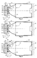
- FIGS. 1 to 3 is schematically shown a mounting and measuring structure for automatically fixing two components of an LED light.
- the LED lamp 10 in this case has an LED module 12 and an optical unit 14.
- the two components of the LED lamp 10 are subject to tolerances. In order nevertheless to be able to achieve a required light intensity at a prescribed distance from the LED light, the two components are displaced relative to one another along the optical axis 16 of the LED light 10 during the assembly process until, with the aid of a detector 18, a relative position corresponding to the desired light intensity has been found.
- the detector 18 is located within a particular telescoping tube 20, wherein at one end of this tube 20, the detector 18 and at the opposite other end of the tube 20, the optical unit 14 is arranged.
- the tube 20 is therefore preferably telescopic in order to be able to measure with the aid of the measurement setup LED lights 10, which should have at different distances over predetermined light intensities. Thus, therefore, the distance of the detector 18 to the LED lamp 10 can be adjusted by telescoping the tube 20.
- the LED module 12 has an LED 22 with a die 24 and a transparent potting compound 26.
- the LED 22 is arranged on a circuit board 28, which optionally has components for driving the LED 22 and contact elements for electrical contacting.
- the circuit board 28 is located on a heat sink 30.
- the optical unit 14 has in this embodiment, a reflector 32 which is provided with a light exit opening 34 and an LED receiving opening 36.
- the reflector 32 is provided at its end provided with the opening 36 with in this embodiment three connecting webs 38, which are arranged distributed uniformly in the circumferential direction of the rotationally symmetrical reflector 32.
- the three connecting webs 38 are assigned three recesses 40 in the board 28. In these recesses adhesive mass 42 is applied, in which the ends of the connecting webs 38 are immersed in the assembly of the LED lamp 10.
- the tube 20 and the reflector 32 are rigid during assembly and measurement of the LED light 10, so are not movable along the optical axis 16 relative to each other.
- the LED module 12 can be moved back and forth in the direction of the optical axis 16 (see the double arrow 46).
- the LED module 12 could be arranged fixed and the unit of reflector 32 and tube 20 and measuring plane with detector 18 along the optical axis 16 to be movable.
- the LED 22 is driven to emit light. This light is detected by the detector 18 within the measurement plane. Subsequently, the LED module 12 is moved until the detector 18 detects a light intensity, as required in the prescribed distance to the LED light. When moving apart of the two components, the adhesive masses 42 are pulled "in the length".
- Fig. 2 shows the relative position of LED module 12 and optical unit 14, in which the detector 18 measures the desired light intensity.
- the LED module 12 and the optical unit 14 are interconnected by the adhesive masses 42.
- the curing of the adhesive mass 42 which is in Fig. 3 at 50 for the example of a cure of the adhesive masses 42 with the aid of UV radiation is shown.
- the assembly of the two components of the LED lamp 10, namely the LED module 12 and the optical unit 14 is completed. Thereafter, the further production of the LED light with lens and possibly a housing, which is not shown in the drawing.
- the LED lamp has a reflective optical unit in the form of the reflector 32.
- the LED light can also be provided with a lens (refractive optical unit).
- the LED lamp with an optical unit with refractive and reflective optical elements can be mounted / assembled in the manner according to the invention.
Landscapes
- Engineering & Computer Science (AREA)
- Physics & Mathematics (AREA)
- General Engineering & Computer Science (AREA)
- Optics & Photonics (AREA)
- General Physics & Mathematics (AREA)
- Mechanical Engineering (AREA)
- Microelectronics & Electronic Packaging (AREA)
- Non-Portable Lighting Devices Or Systems Thereof (AREA)
Claims (3)
- Procédé de montage d'une lampe de lecture ou de siège à LED qui comprend un module à LED et une unité optique réflective et/ou réfractive pour un véhicule tel qu'un aéronef ou un bus, avec les étapes suivantes :- la fourniture d'un module à LED (12) qui comprend au moins une LED (22),- la fourniture d'une unité optique (14) comprenant un réflecteur et/ou une lentille pour l'illumination dans un plan de mesure par rayonnement électromagnétique du module à LED (12) et de l'unité optique (14),- l'agencement de l'unité optique (14) et du module à LED (12) en vue d'une attache ultérieure l'un à l'autre,- le contrôle du module à LED (12) pour la transmission du rayonnement électromagnétique en vue d'une illumination dans le plan de mesure,- la détection par un détecteur (18) d'au moins une partie du rayonnement électromagnétique du module à LED (12) incidente sur le plan de mesure,- le déplacement du module à LED (12) par rapport à l'unité optique (14) et/ou de l'unité optique (14) par rapport au module à LED (12) le long de l'axe optique (16) jusqu'à ce que le détecteur (18) détecte le rayonnement électromagnétique du module à LED (12) avec une intensité prédéterminable et- l'attache de l'unité optique (14) et du module à LED (12) l'un par rapport à l'autre dans leurs positions relatives actuelles.
- Procédé selon la revendication 1, caractérisé en ce que dans l'agencement du module à LED (12) et de l'unité optique (14) en vue d'une attache ultérieure l'un à l'autre, une composition adhésive (42) qui peut être durcie est appliquée aux sites de contact mécanique (46) entre le module à LED (12) et l'unité optique (14) et en ce que le module à LED (12) et l'unité optique (14) restent reliés par la composition adhésive (42) lorsqu'ils sont déplacés l'un par rapport à l'autre le long de l'axe optique (16).
- Procédé selon la revendication 2, caractérisé en ce que la composition adhésive (42) peut être durcie par rayonnement ultraviolet (50) et en ce que l'attache du module à LED (12) et de l'unité optique (14) apparaît par irradiation ultraviolette de la composition adhésive (42) s'étendant entre eux.
Priority Applications (2)
| Application Number | Priority Date | Filing Date | Title |
|---|---|---|---|
| EP08101709.7A EP1995513B1 (fr) | 2007-05-22 | 2008-02-18 | Procédé destiné au montage d'une lampe à DEL |
| US12/125,645 US8006376B2 (en) | 2007-05-22 | 2008-05-22 | Method for assembly of an LED light |
Applications Claiming Priority (2)
| Application Number | Priority Date | Filing Date | Title |
|---|---|---|---|
| EP07108613 | 2007-05-22 | ||
| EP08101709.7A EP1995513B1 (fr) | 2007-05-22 | 2008-02-18 | Procédé destiné au montage d'une lampe à DEL |
Publications (2)
| Publication Number | Publication Date |
|---|---|
| EP1995513A1 EP1995513A1 (fr) | 2008-11-26 |
| EP1995513B1 true EP1995513B1 (fr) | 2015-10-21 |
Family
ID=38561747
Family Applications (1)
| Application Number | Title | Priority Date | Filing Date |
|---|---|---|---|
| EP08101709.7A Active EP1995513B1 (fr) | 2007-05-22 | 2008-02-18 | Procédé destiné au montage d'une lampe à DEL |
Country Status (2)
| Country | Link |
|---|---|
| US (1) | US8006376B2 (fr) |
| EP (1) | EP1995513B1 (fr) |
Families Citing this family (5)
| Publication number | Priority date | Publication date | Assignee | Title |
|---|---|---|---|---|
| US7874055B2 (en) * | 2005-03-04 | 2011-01-25 | Musco Corporation | Method and system for assembly of lighting fixtures |
| JP2014011045A (ja) * | 2012-06-29 | 2014-01-20 | Toshiba Lighting & Technology Corp | 照明装置及び照明システム |
| JP2014107229A (ja) * | 2012-11-29 | 2014-06-09 | Toshiba Lighting & Technology Corp | 発光装置および車両用照明装置 |
| EP3095710B1 (fr) * | 2015-05-20 | 2018-01-03 | Goodrich Lighting Systems GmbH | Unité d'éclairage extérieur d'aéronef et procédé de fonctionnement associé |
| US20160366395A1 (en) * | 2015-06-12 | 2016-12-15 | Microsoft Technology Licensing, Llc | Led surface emitting structured light |
Family Cites Families (7)
| Publication number | Priority date | Publication date | Assignee | Title |
|---|---|---|---|---|
| US4237474A (en) | 1978-10-18 | 1980-12-02 | Rca Corporation | Electroluminescent diode and optical fiber assembly |
| US4500165A (en) | 1982-04-02 | 1985-02-19 | Codenoll Technology Corporation | Method and apparatus for aligning optical fibers |
| EP0420214A3 (en) * | 1989-09-27 | 1991-08-28 | Toshiba Lighting & Technology Corporation | Lamp device and method of bonding mirror reflector to lamp |
| FR2668268B1 (fr) * | 1990-10-19 | 1993-08-27 | Thomson Hybrides | Dispositif d'alignement d'une fibre optique et d'un composant optoelectronique. |
| FR2767928B1 (fr) | 1997-09-01 | 2000-01-14 | Alliance Tech Ind | Dispositif de couplage d'une fibre optique a une source, et procede de fixation d'une embase d'un tel dispositif |
| EP1200775A1 (fr) * | 1999-07-01 | 2002-05-02 | Jari Ruuttu | Structure de lampe |
| US20080074884A1 (en) * | 2006-09-25 | 2008-03-27 | Thye Linn Mok | Compact high-intensty LED-based light source and method for making the same |
-
2008
- 2008-02-18 EP EP08101709.7A patent/EP1995513B1/fr active Active
- 2008-05-22 US US12/125,645 patent/US8006376B2/en active Active
Also Published As
| Publication number | Publication date |
|---|---|
| US20090025202A1 (en) | 2009-01-29 |
| US8006376B2 (en) | 2011-08-30 |
| EP1995513A1 (fr) | 2008-11-26 |
Similar Documents
| Publication | Publication Date | Title |
|---|---|---|
| EP2693106B1 (fr) | Module d'éclairage | |
| EP3339720B1 (fr) | Ensemble d'optique primaire destiné à être utilisé dans un dispositif d'éclairage du véhicule automobile et dispositif d'éclairage du véhicule automobile doté d'un tel ensemble d'optique primaire | |
| EP1995513B1 (fr) | Procédé destiné au montage d'une lampe à DEL | |
| DE102012213841A1 (de) | Lichtmodul | |
| EP3321570B1 (fr) | Procédé d'agencement d'un support de circuit et dispositif d'éclairage de véhicule automobile pourvu de support de circuit selon le procédé | |
| WO2017029255A2 (fr) | Procédé d'ajustage d'une tache lumineuse générée sur un convertisseur optique, dispositif comprenant une tache lumineuse et son utilisation ainsi que composé convertisseur - corps de refroidissement comprenant une liaison soudée métallique | |
| DE102010054922B4 (de) | Scheinwerfer für ein Fahrzeug mit einer Halbleiterlichtquelle | |
| DE102006039705A1 (de) | Linsenvorsatz für einen Scheinwerfer | |
| WO2016094913A1 (fr) | Procédé de fabrication d'un support de circuit et support de circuit | |
| DE10341884B4 (de) | Flexible Schaltungsträgeranordnung | |
| DE202017001946U1 (de) | Scheinwerfer mit einem optischen System mit statischem Matrix-Abbiegelicht | |
| EP3671014B1 (fr) | Module de phares à del et module lumineux à del destiné à être utilisé dans un tel module de phares à del | |
| DE102009023645A1 (de) | LED-Modul | |
| EP1925876B1 (fr) | Système de source lumineuse DEL | |
| EP3088798B1 (fr) | Procede et dispositif d'agencement d'un porte-circuit comprenant une source lumineuse semi-conductrice dans un emplacement defini par rapport a un systeme optique d'un dispositif d'eclairage | |
| DE102009054101A1 (de) | Beleuchtungsvorrichtung für ein Fahrzeug | |
| EP3452753B1 (fr) | Dispositif de montage d'un porte-circuit | |
| DE102016105730A1 (de) | Verfahren und Gerät zum Reduzieren von Rändern des Lichtbilds eines Scheinwerfers und Scheinwerfer | |
| EP3165818A1 (fr) | Éclairage intérieur ou extérieur, en particulier réverbère comprenant une lentille à forme libre pouvant être décalée | |
| WO2012150121A1 (fr) | Dispositif émetteur de rayonnement et utilisation d'un tel dispositif | |
| EP2664496B1 (fr) | Procédé destiné à la fabrication de lampes de véhicules automobiles | |
| EP3961088A1 (fr) | Phares de véhicule automobile | |
| WO2018210696A1 (fr) | Procédé de montage d'un module lumineux pour dispositif d'éclairage | |
| AT518951B1 (de) | Verfahren zum Einstellen eines von einer Kraftfahrzeugbeleuchtungsvorrichtung abgestrahlten Lichtstroms und eine Kraftfahrzeugbeleuchtungsvorrichtung zum Abstrahlen des eingestellten Lichtstroms | |
| DE19851640A1 (de) | Prüfvorrichtung zur Kontrolle der Einstellung der Helldunkelgrenze des von einem Scheinwerfer ausgesandten Lichtbündels und Verfahren zur Ausrichtung und zum Anbau eines Scheinwerfers unter Verwendung der Prüfvorrichtung |
Legal Events
| Date | Code | Title | Description |
|---|---|---|---|
| PUAI | Public reference made under article 153(3) epc to a published international application that has entered the european phase |
Free format text: ORIGINAL CODE: 0009012 |
|
| AK | Designated contracting states |
Kind code of ref document: A1 Designated state(s): AT BE BG CH CY CZ DE DK EE ES FI FR GB GR HR HU IE IS IT LI LT LU LV MC MT NL NO PL PT RO SE SI SK TR |
|
| AX | Request for extension of the european patent |
Extension state: AL BA MK RS |
|
| 17P | Request for examination filed |
Effective date: 20090421 |
|
| 17Q | First examination report despatched |
Effective date: 20090615 |
|
| AKX | Designation fees paid |
Designated state(s): AT BE BG CH CY CZ DE DK EE ES FI FR GB GR HR HU IE IS IT LI LT LU LV MC MT NL NO PL PT RO SE SI SK TR |
|
| GRAP | Despatch of communication of intention to grant a patent |
Free format text: ORIGINAL CODE: EPIDOSNIGR1 |
|
| INTG | Intention to grant announced |
Effective date: 20150326 |
|
| GRAS | Grant fee paid |
Free format text: ORIGINAL CODE: EPIDOSNIGR3 |
|
| GRAA | (expected) grant |
Free format text: ORIGINAL CODE: 0009210 |
|
| AK | Designated contracting states |
Kind code of ref document: B1 Designated state(s): AT BE BG CH CY CZ DE DK EE ES FI FR GB GR HR HU IE IS IT LI LT LU LV MC MT NL NO PL PT RO SE SI SK TR |
|
| REG | Reference to a national code |
Ref country code: GB Ref legal event code: FG4D Free format text: NOT ENGLISH Ref country code: NL Ref legal event code: MP Effective date: 20151021 |
|
| REG | Reference to a national code |
Ref country code: CH Ref legal event code: EP |
|
| REG | Reference to a national code |
Ref country code: AT Ref legal event code: REF Ref document number: 756846 Country of ref document: AT Kind code of ref document: T Effective date: 20151115 |
|
| REG | Reference to a national code |
Ref country code: IE Ref legal event code: FG4D Free format text: LANGUAGE OF EP DOCUMENT: GERMAN |
|
| REG | Reference to a national code |
Ref country code: DE Ref legal event code: R096 Ref document number: 502008013496 Country of ref document: DE |
|
| REG | Reference to a national code |
Ref country code: FR Ref legal event code: PLFP Year of fee payment: 9 |
|
| REG | Reference to a national code |
Ref country code: LT Ref legal event code: MG4D |
|
| PG25 | Lapsed in a contracting state [announced via postgrant information from national office to epo] |
Ref country code: NL Free format text: LAPSE BECAUSE OF FAILURE TO SUBMIT A TRANSLATION OF THE DESCRIPTION OR TO PAY THE FEE WITHIN THE PRESCRIBED TIME-LIMIT Effective date: 20151021 Ref country code: IT Free format text: LAPSE BECAUSE OF FAILURE TO SUBMIT A TRANSLATION OF THE DESCRIPTION OR TO PAY THE FEE WITHIN THE PRESCRIBED TIME-LIMIT Effective date: 20151021 Ref country code: NO Free format text: LAPSE BECAUSE OF FAILURE TO SUBMIT A TRANSLATION OF THE DESCRIPTION OR TO PAY THE FEE WITHIN THE PRESCRIBED TIME-LIMIT Effective date: 20160121 Ref country code: ES Free format text: LAPSE BECAUSE OF FAILURE TO SUBMIT A TRANSLATION OF THE DESCRIPTION OR TO PAY THE FEE WITHIN THE PRESCRIBED TIME-LIMIT Effective date: 20151021 Ref country code: IS Free format text: LAPSE BECAUSE OF FAILURE TO SUBMIT A TRANSLATION OF THE DESCRIPTION OR TO PAY THE FEE WITHIN THE PRESCRIBED TIME-LIMIT Effective date: 20160221 Ref country code: LT Free format text: LAPSE BECAUSE OF FAILURE TO SUBMIT A TRANSLATION OF THE DESCRIPTION OR TO PAY THE FEE WITHIN THE PRESCRIBED TIME-LIMIT Effective date: 20151021 Ref country code: HR Free format text: LAPSE BECAUSE OF FAILURE TO SUBMIT A TRANSLATION OF THE DESCRIPTION OR TO PAY THE FEE WITHIN THE PRESCRIBED TIME-LIMIT Effective date: 20151021 |
|
| PG25 | Lapsed in a contracting state [announced via postgrant information from national office to epo] |
Ref country code: LV Free format text: LAPSE BECAUSE OF FAILURE TO SUBMIT A TRANSLATION OF THE DESCRIPTION OR TO PAY THE FEE WITHIN THE PRESCRIBED TIME-LIMIT Effective date: 20151021 Ref country code: PL Free format text: LAPSE BECAUSE OF FAILURE TO SUBMIT A TRANSLATION OF THE DESCRIPTION OR TO PAY THE FEE WITHIN THE PRESCRIBED TIME-LIMIT Effective date: 20151021 Ref country code: PT Free format text: LAPSE BECAUSE OF FAILURE TO SUBMIT A TRANSLATION OF THE DESCRIPTION OR TO PAY THE FEE WITHIN THE PRESCRIBED TIME-LIMIT Effective date: 20160222 Ref country code: SE Free format text: LAPSE BECAUSE OF FAILURE TO SUBMIT A TRANSLATION OF THE DESCRIPTION OR TO PAY THE FEE WITHIN THE PRESCRIBED TIME-LIMIT Effective date: 20151021 Ref country code: FI Free format text: LAPSE BECAUSE OF FAILURE TO SUBMIT A TRANSLATION OF THE DESCRIPTION OR TO PAY THE FEE WITHIN THE PRESCRIBED TIME-LIMIT Effective date: 20151021 Ref country code: GR Free format text: LAPSE BECAUSE OF FAILURE TO SUBMIT A TRANSLATION OF THE DESCRIPTION OR TO PAY THE FEE WITHIN THE PRESCRIBED TIME-LIMIT Effective date: 20160122 Ref country code: BE Free format text: LAPSE BECAUSE OF NON-PAYMENT OF DUE FEES Effective date: 20160229 |
|
| REG | Reference to a national code |
Ref country code: DE Ref legal event code: R097 Ref document number: 502008013496 Country of ref document: DE |
|
| PG25 | Lapsed in a contracting state [announced via postgrant information from national office to epo] |
Ref country code: CZ Free format text: LAPSE BECAUSE OF FAILURE TO SUBMIT A TRANSLATION OF THE DESCRIPTION OR TO PAY THE FEE WITHIN THE PRESCRIBED TIME-LIMIT Effective date: 20151021 |
|
| PLBE | No opposition filed within time limit |
Free format text: ORIGINAL CODE: 0009261 |
|
| STAA | Information on the status of an ep patent application or granted ep patent |
Free format text: STATUS: NO OPPOSITION FILED WITHIN TIME LIMIT |
|
| PG25 | Lapsed in a contracting state [announced via postgrant information from national office to epo] |
Ref country code: RO Free format text: LAPSE BECAUSE OF FAILURE TO SUBMIT A TRANSLATION OF THE DESCRIPTION OR TO PAY THE FEE WITHIN THE PRESCRIBED TIME-LIMIT Effective date: 20151021 Ref country code: DK Free format text: LAPSE BECAUSE OF FAILURE TO SUBMIT A TRANSLATION OF THE DESCRIPTION OR TO PAY THE FEE WITHIN THE PRESCRIBED TIME-LIMIT Effective date: 20151021 Ref country code: SK Free format text: LAPSE BECAUSE OF FAILURE TO SUBMIT A TRANSLATION OF THE DESCRIPTION OR TO PAY THE FEE WITHIN THE PRESCRIBED TIME-LIMIT Effective date: 20151021 Ref country code: EE Free format text: LAPSE BECAUSE OF FAILURE TO SUBMIT A TRANSLATION OF THE DESCRIPTION OR TO PAY THE FEE WITHIN THE PRESCRIBED TIME-LIMIT Effective date: 20151021 |
|
| 26N | No opposition filed |
Effective date: 20160722 |
|
| PG25 | Lapsed in a contracting state [announced via postgrant information from national office to epo] |
Ref country code: LU Free format text: LAPSE BECAUSE OF FAILURE TO SUBMIT A TRANSLATION OF THE DESCRIPTION OR TO PAY THE FEE WITHIN THE PRESCRIBED TIME-LIMIT Effective date: 20160218 Ref country code: MC Free format text: LAPSE BECAUSE OF FAILURE TO SUBMIT A TRANSLATION OF THE DESCRIPTION OR TO PAY THE FEE WITHIN THE PRESCRIBED TIME-LIMIT Effective date: 20151021 |
|
| REG | Reference to a national code |
Ref country code: CH Ref legal event code: PL |
|
| PG25 | Lapsed in a contracting state [announced via postgrant information from national office to epo] |
Ref country code: CH Free format text: LAPSE BECAUSE OF NON-PAYMENT OF DUE FEES Effective date: 20160229 Ref country code: LI Free format text: LAPSE BECAUSE OF NON-PAYMENT OF DUE FEES Effective date: 20160229 |
|
| PG25 | Lapsed in a contracting state [announced via postgrant information from national office to epo] |
Ref country code: SI Free format text: LAPSE BECAUSE OF FAILURE TO SUBMIT A TRANSLATION OF THE DESCRIPTION OR TO PAY THE FEE WITHIN THE PRESCRIBED TIME-LIMIT Effective date: 20151021 |
|
| REG | Reference to a national code |
Ref country code: IE Ref legal event code: MM4A |
|
| REG | Reference to a national code |
Ref country code: FR Ref legal event code: PLFP Year of fee payment: 10 |
|
| PG25 | Lapsed in a contracting state [announced via postgrant information from national office to epo] |
Ref country code: IE Free format text: LAPSE BECAUSE OF NON-PAYMENT OF DUE FEES Effective date: 20160218 |
|
| REG | Reference to a national code |
Ref country code: AT Ref legal event code: MM01 Ref document number: 756846 Country of ref document: AT Kind code of ref document: T Effective date: 20160218 |
|
| PG25 | Lapsed in a contracting state [announced via postgrant information from national office to epo] |
Ref country code: AT Free format text: LAPSE BECAUSE OF NON-PAYMENT OF DUE FEES Effective date: 20160218 |
|
| REG | Reference to a national code |
Ref country code: DE Ref legal event code: R082 Ref document number: 502008013496 Country of ref document: DE Representative=s name: SCHMITT-NILSON SCHRAUD WAIBEL WOHLFROM PATENTA, DE |
|
| PG25 | Lapsed in a contracting state [announced via postgrant information from national office to epo] |
Ref country code: MT Free format text: LAPSE BECAUSE OF FAILURE TO SUBMIT A TRANSLATION OF THE DESCRIPTION OR TO PAY THE FEE WITHIN THE PRESCRIBED TIME-LIMIT Effective date: 20151021 |
|
| REG | Reference to a national code |
Ref country code: FR Ref legal event code: PLFP Year of fee payment: 11 |
|
| PG25 | Lapsed in a contracting state [announced via postgrant information from national office to epo] |
Ref country code: HU Free format text: LAPSE BECAUSE OF FAILURE TO SUBMIT A TRANSLATION OF THE DESCRIPTION OR TO PAY THE FEE WITHIN THE PRESCRIBED TIME-LIMIT; INVALID AB INITIO Effective date: 20080218 Ref country code: CY Free format text: LAPSE BECAUSE OF FAILURE TO SUBMIT A TRANSLATION OF THE DESCRIPTION OR TO PAY THE FEE WITHIN THE PRESCRIBED TIME-LIMIT Effective date: 20151021 |
|
| PG25 | Lapsed in a contracting state [announced via postgrant information from national office to epo] |
Ref country code: TR Free format text: LAPSE BECAUSE OF FAILURE TO SUBMIT A TRANSLATION OF THE DESCRIPTION OR TO PAY THE FEE WITHIN THE PRESCRIBED TIME-LIMIT Effective date: 20151021 |
|
| PG25 | Lapsed in a contracting state [announced via postgrant information from national office to epo] |
Ref country code: BG Free format text: LAPSE BECAUSE OF FAILURE TO SUBMIT A TRANSLATION OF THE DESCRIPTION OR TO PAY THE FEE WITHIN THE PRESCRIBED TIME-LIMIT Effective date: 20151021 |
|
| RIC2 | Information provided on ipc code assigned after grant |
Ipc: G02B 27/62 20060101ALI20080710BHEP Ipc: F21Y 101/02 20000101ALN20080710BHEP Ipc: G02B 7/182 20060101ALI20080710BHEP Ipc: F21V 17/10 20060101AFI20080710BHEP Ipc: G02B 7/00 20060101ALI20080710BHEP |
|
| P01 | Opt-out of the competence of the unified patent court (upc) registered |
Effective date: 20230630 |
|
| PGFP | Annual fee paid to national office [announced via postgrant information from national office to epo] |
Ref country code: GB Payment date: 20260121 Year of fee payment: 19 |
|
| PGFP | Annual fee paid to national office [announced via postgrant information from national office to epo] |
Ref country code: DE Payment date: 20260121 Year of fee payment: 19 |
|
| PGFP | Annual fee paid to national office [announced via postgrant information from national office to epo] |
Ref country code: FR Payment date: 20260121 Year of fee payment: 19 |