EP1995532A1 - Vorrichtung zur Luftverteilung in einem Raum eines Gebäudes - Google Patents
Vorrichtung zur Luftverteilung in einem Raum eines Gebäudes Download PDFInfo
- Publication number
- EP1995532A1 EP1995532A1 EP08356070A EP08356070A EP1995532A1 EP 1995532 A1 EP1995532 A1 EP 1995532A1 EP 08356070 A EP08356070 A EP 08356070A EP 08356070 A EP08356070 A EP 08356070A EP 1995532 A1 EP1995532 A1 EP 1995532A1
- Authority
- EP
- European Patent Office
- Prior art keywords
- plenum
- air
- diffusion device
- plate
- opening
- Prior art date
- Legal status (The legal status is an assumption and is not a legal conclusion. Google has not performed a legal analysis and makes no representation as to the accuracy of the status listed.)
- Withdrawn
Links
- 238000009423 ventilation Methods 0.000 claims abstract description 6
- 238000009792 diffusion process Methods 0.000 claims description 43
- 238000007664 blowing Methods 0.000 claims description 15
- 238000009434 installation Methods 0.000 claims description 7
- 239000000463 material Substances 0.000 claims description 5
- 230000002745 absorbent Effects 0.000 claims description 4
- 239000002250 absorbent Substances 0.000 claims description 4
- 230000002093 peripheral effect Effects 0.000 description 3
- 235000021183 entrée Nutrition 0.000 description 2
- 239000006260 foam Substances 0.000 description 2
- 238000010438 heat treatment Methods 0.000 description 2
- 238000004378 air conditioning Methods 0.000 description 1
- 210000004027 cell Anatomy 0.000 description 1
- 238000001816 cooling Methods 0.000 description 1
- 230000003247 decreasing effect Effects 0.000 description 1
- 230000006870 function Effects 0.000 description 1
- 230000006698 induction Effects 0.000 description 1
- 230000001737 promoting effect Effects 0.000 description 1
- 230000001902 propagating effect Effects 0.000 description 1
- 230000035807 sensation Effects 0.000 description 1
- 239000007787 solid Substances 0.000 description 1
- 238000003756 stirring Methods 0.000 description 1
- 238000011144 upstream manufacturing Methods 0.000 description 1
Images


Classifications
-
- F—MECHANICAL ENGINEERING; LIGHTING; HEATING; WEAPONS; BLASTING
- F24—HEATING; RANGES; VENTILATING
- F24F—AIR-CONDITIONING; AIR-HUMIDIFICATION; VENTILATION; USE OF AIR CURRENTS FOR SCREENING
- F24F13/00—Details common to, or for air-conditioning, air-humidification, ventilation or use of air currents for screening
- F24F13/02—Ducting arrangements
- F24F13/06—Outlets for directing or distributing air into rooms or spaces, e.g. ceiling air diffuser
-
- F—MECHANICAL ENGINEERING; LIGHTING; HEATING; WEAPONS; BLASTING
- F24—HEATING; RANGES; VENTILATING
- F24F—AIR-CONDITIONING; AIR-HUMIDIFICATION; VENTILATION; USE OF AIR CURRENTS FOR SCREENING
- F24F13/00—Details common to, or for air-conditioning, air-humidification, ventilation or use of air currents for screening
- F24F13/02—Ducting arrangements
- F24F13/06—Outlets for directing or distributing air into rooms or spaces, e.g. ceiling air diffuser
- F24F2013/0616—Outlets that have intake openings
-
- F—MECHANICAL ENGINEERING; LIGHTING; HEATING; WEAPONS; BLASTING
- F24—HEATING; RANGES; VENTILATING
- F24F—AIR-CONDITIONING; AIR-HUMIDIFICATION; VENTILATION; USE OF AIR CURRENTS FOR SCREENING
- F24F2221/00—Details or features not otherwise provided for
- F24F2221/14—Details or features not otherwise provided for mounted on the ceiling
-
- F—MECHANICAL ENGINEERING; LIGHTING; HEATING; WEAPONS; BLASTING
- F24—HEATING; RANGES; VENTILATING
- F24F—AIR-CONDITIONING; AIR-HUMIDIFICATION; VENTILATION; USE OF AIR CURRENTS FOR SCREENING
- F24F2221/00—Details or features not otherwise provided for
- F24F2221/46—Air flow forming a vortex
Definitions
- the present invention relates to a diffusion device for mounting to the ceiling of a room of a building and to be connected to a ventilation system of the building for blowing air into said room.
- the diffusion device constitutes the terminal member of a mechanized blowing installation of a ventilation installation, in particular for heating and / or cooling the building.
- such a device comprises a plenum which has, in the mounted position, a substantially vertical axis, the plenum comprising an upper wall, a side wall in which is provided an air inlet orifice intended to be connected to said installation and a lower wall in which is provided an air blowing opening in said room.
- the "flat" jet diffusers on the one hand, generally comprise, opposite the insufflation opening, a series of fins fixed to the plenum and arranged in concentric squares or circles, thus causing the blowing of air in the room according to a plurality of flat jets.
- the diffusion devices of this first family make it possible to obtain a large flow of air, but the comfort they provide may be insufficient because of a small mixing between the air in the room and the air blown in. .
- the "helical" jet diffusion devices generally comprise rotary blades arranged opposite the insufflation opening, which makes it possible to ensure a high degree of mixing between the blown air and the air of the nozzle. the room, even at low residual speeds.
- the diffusion devices of this second family are a very interesting solution for providing satisfactory comfort in a room.
- these diffusion devices do not allow blowing air at high flow rates, because of their structure (presence of small nozzles, small deflectors, etc.).
- the document EP 1 118 820 discloses an air suction device in which are provided means for creating a spiral of blown air, surrounding the suction air column.
- the blown air passes through a number of stators arranged in a ring in the lower part of the plenum, and forms a cone surrounding the sucked air. Due to the presence of the stators, the air can not be blown with a high flow rate.
- the device described in this This document would not be appropriate for an application in the field of heating or air-conditioning of buildings.
- the present invention aims to overcome the drawbacks mentioned above, by providing a diffusion device that allows both to obtain satisfactory comfort and significant blowing rates.
- the invention provides for the rotation of air inside the plenum, by the particular geometry thereof, upstream of the diffusion opening, and to ensure that the air is always in sufficient rotation when it is diffused in the room, thanks to the plate. Since this rotation is not obtained by small nozzles or vanes, as in prior art helical jet devices, it is possible to obtain large inflated air flow rates comparable to those obtained. with flat fan diffusion devices.
- the passage of the air flow, at the periphery of the plate is free, that is to say devoid of any member acting on this air flow (such as nozzles, deflectors, fins, etc.)
- the open lower end of the main part of the plenum is merged with the insufflation opening.
- the plate is generally flat, but may have a slightly convex shape upwards.
- the main part of the plenum has a substantially parallelepipedal shape and the inlet is formed in one of the four faces of the side wall offset from the vertical median of said face. It is therefore the off-center position of the stitching which here allows the rotation of the air in the plenum.
- the main part of the plenum has substantially a volute shape.
- the rotation of the air is obtained by the shape of the side wall of the plenum, similar to the volute of a turbine.
- the main part of the plenum may be substantially cylindrical and the inlet orifice in the side wall offset from the axis of this cylindrical portion.
- the diffusion device may comprise means arranged inside the plenum to promote the swirling movement of the air in the plenum.
- These means can be arranged against the side wall of the plenum.
- a parallelepiped plenum it is thus possible to modify the geometry of the interior space so that it approximates a shape rounded, thus limiting the air vortices located in the corners of the plenum.
- These may be, for example, dihedral elements placed in the corners between the faces of the side wall of the parallelepiped plenum, with the exception of the angle close to the inlet orifice.
- these means may have the shape of the side wall of a volute opening into the inlet port.
- these means promoting the swirling movement of the air in the plenum may be arranged substantially along the axis of the plenum, in the center of the latter. These means, placed in a zone inactive in the aeraulic plane (where the air has a very low speed) then facilitate a peripheral speed of the air in the plenum.
- said means may comprise an acoustically absorbent material, which also allows them to limit the noise generated, especially the noise caused by the air handling unit and propagating in the ducts.
- the plenum comprises an extension of the main part which is flared downwards, said extension having an open bottom end forming the air blowing opening in the room, the plate having horizontal dimensions smaller than those of the lower open end of the plenum extension.
- the plate may be located substantially in the same plane as the lower edge of the plenum. In other words, the plate may be located substantially in the same plane as the lower edge of the extension, in the same plane as the air blowing opening. This arrangement promotes the obtaining of a flat air jet, and also meets aesthetic considerations, since it is then possible that no element of the diffusion device does not exceed below the ceiling.
- the plate is located at a distance from the lower edge of the plenum below said edge, and has dimensions greater than those of the insufflation opening.
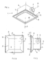
- the invention relates to a diffusion device 1 comprising a plenum 2 having an axis 3 and comprising an upper wall 4, a side wall 5 and a bottom wall 6.
- the diffusion device is described in the position it occupies when it is mounted on the ceiling or the false ceiling of a room of a building, the axis 3 then being substantially vertical.
- An air inlet opening 7 is formed in the side wall 5 of the plenum 2.
- the orifice 7, which has a substantially horizontal axis 8, is intended to be connected to a duct of a ventilation installation of the building.
- an opening 9 of air blowing is formed in the lower wall 6 of the plenum 2. This opening 9 is substantially centered on the axis 3 of the plenum 2.
- the diffusion device 1 comprises a plate 10 fixed in the lower part of the plenum 2, facing the opening 9 of insufflation, leaving at the outlet of the plenum 2 a peripheral passage for the diffused air.
- the plenum 2 comprises a substantially parallelepipedal main part, the side wall 5 of which forms four identical vertical rectangular faces.
- the plenum 2 also comprises an extension 11 in the form of a pyramid section with a square base flaring downwards.
- the opening 9 is here substantially square.
- the plate 10 is full. It has a substantially square contour whose sides are parallel to the faces of the side wall 5, and may have a slightly convex shape towards the inside of the plenum 2.
- the plate 10 is fixed by any appropriate means to the plenum 2, centrally on the axis 3, and is located generally in the same plane as the lower edge of the extension 11. As illustrated in FIG. figure 3 the length of one side of the plate 10 is between the length of one side of the side wall 5 and the length of one side of the lower edge of the extension 11.
- the air intake port 7 is located on one side of the side wall 5, in the upper part of the plenum 2, and off-center, that is to say that the axis 8 of this orifice 7 do not cut the axis 3 of the plenum.
- the orifice 7 is circular and shifted as much as possible towards a vertical side of the face of the side wall 5 in which it is arranged.
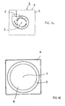
- This plenum 2 is more specifically represented on Figures 4 and 5 .
- the air entering the plenum 2 undergoes a swirling movement around the axis 3 and down to the plate 10.
- the air thus passes by turning in the extension 11 and is broadcast in the piece, always turning, passing around the plate 10.
- the invention provides for placing inside the plenum 2 means making the inner section of the plenum 2 closer to a circle.
- dihedrons 12 may be disposed in each of the corners of the lateral face 5 of the main portion of the plenum 2, with the exception of the angle closest to the orifice 7.
- the air entering through the orifice 7 can thus more easily rotate around the axis 3, and the yield losses resulting from the appearance of vortices in the corners of the plenum 2 are considerably reduced.
- a curved wall 13 can be arranged inside the plenum 2, creating a volute shape connected to the orifice 7.
- the dihedrons 12 and the curved wall 13 may be made of any material sufficiently rigid to allow the air to be channeled into the plenum 2. They may in particular be made of an acoustically absorbent material, such as a foam, to further fulfill a function of 'soundproofing.
- the air passes between the extension 11 and the plate 10, according to a very confined area of truncated cone. So, as illustrated by the arrows on the figure 3 , the air is ejected from the plenum 2 with a very small angle relative to the horizontal, that is to say almost perpendicular to the axis 3.
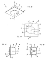
- FIGS 10 to 15 represent a second embodiment, in which the plenum 2 has a main part in the form of a volute.
- the plenum 2 comprises a main part comprising a flat upper and horizontal wall 4 and a substantially cylindrical side wall 5 and open at its lower end 17.
- the air inlet opening 7 is formed in the side wall 5, the 8 axis of the orifice 7 being offset with respect to the vertical axis 3 of the plenum 2, similar to the volute of a turbine.
- the plenum 2 has an extension 11 extending from the lower end 17 of the main part and flaring downwards.
- the extension 11 is here substantially truncated cone and has a lower cylindrical rim 18. It defines the inflation opening 9, which is here circular.
- the lower wall 6 of the plenum 2 may consist of a square plate centered on the axis 3 and of dimensions greater than those of the cylindrical rim 18, provided with a central orifice corresponding to the opening 9.
- the plenum 2 (main part and extension 11) and the bottom wall 6 form a single piece, as illustrated in FIG. figure 13 .
- the plate 10 here has the shape of a solid disk of diameter less than the diameter of the opening 9, but greater than the diameter of the cylindrical side wall. This plate 10 is fixed to the plenum 2 centrally on the axis 3, substantially in the plane of the lower wall 6.
- the gyration of the air inside the plenum 2 is obtained by the volute shape, including the offset of the air intake port 7 with respect to the axis 3.
- the air entering the plenum 2 through the orifice 7 undergoes a downward gyration movement about the axis 3 and leaves the plenum 2 by the unclosed zone of the blowing opening 9, here formed of a ring at the periphery of the plate 10 (see Figures 13 to 15 ).
- the outlet air is diffused in a substantially horizontal plane.
- a third embodiment of the invention is illustrated on the Figures 16 to 19 .
- the plenum 2 is devoid of extension, and comprises only the main part in the form of volute (here comprising a side wall with a substantially flat portion 14 in which is formed the orifice 7 of air intake and a curved portion 15).
- This disk-shaped plate 10 is here disposed at a distance from the lower wall 6 of the plenum 2, below it, and has a diameter greater than that of the insufflation opening 9 (see in particular FIG. figure 18 ).
- the diffusion device 1 may be provided, inside the plenum, with a conical element 16, fixed on the plate 10 centrally with respect to the axis 3, converging upwards. This element promotes the swirling movement of the air in the plenum 2, around the axis 3 and also limits the noise generated by the diffusion device if it is made of an acoustically absorbent material such as a foam.
- the invention provides a decisive improvement to the prior art, by providing a diffusion device that has a high quality of air diffusion, accompanied by a high induction rate, while allowing air diffusion to large flows.
- Advantages of the invention include acoustic comfort, aesthetics and simplicity of implementation.
Landscapes
- Engineering & Computer Science (AREA)
- Chemical & Material Sciences (AREA)
- Combustion & Propulsion (AREA)
- Mechanical Engineering (AREA)
- General Engineering & Computer Science (AREA)
- Duct Arrangements (AREA)
- Air-Flow Control Members (AREA)
Applications Claiming Priority (1)
| Application Number | Priority Date | Filing Date | Title |
|---|---|---|---|
| FR0703580A FR2916521B1 (fr) | 2007-05-21 | 2007-05-21 | Dispositif de diffusion d'air dans une piece d'un batiment |
Publications (1)
| Publication Number | Publication Date |
|---|---|
| EP1995532A1 true EP1995532A1 (de) | 2008-11-26 |
Family
ID=38895910
Family Applications (1)
| Application Number | Title | Priority Date | Filing Date |
|---|---|---|---|
| EP08356070A Withdrawn EP1995532A1 (de) | 2007-05-21 | 2008-05-20 | Vorrichtung zur Luftverteilung in einem Raum eines Gebäudes |
Country Status (2)
| Country | Link |
|---|---|
| EP (1) | EP1995532A1 (de) |
| FR (1) | FR2916521B1 (de) |
Cited By (2)
| Publication number | Priority date | Publication date | Assignee | Title |
|---|---|---|---|---|
| WO2017214697A1 (en) * | 2016-06-15 | 2017-12-21 | Marble And Marble Ltd. | Register assembly |
| EP3511642A1 (de) * | 2018-01-10 | 2019-07-17 | ZLT Lüftungs- und Brandschutztechnik GmbH | Einbaugehäuse zum ab- oder einleiten von luft |
Citations (5)
| Publication number | Priority date | Publication date | Assignee | Title |
|---|---|---|---|---|
| WO1990010829A1 (fr) * | 1989-03-16 | 1990-09-20 | Atelier Des Ingenieurs Associes, Departement Thermique (A.I.A.T.) | Aerotherme d'axe vertical du type assurant une distribution d'air en effet cyclone |
| JP2000266385A (ja) * | 1999-01-14 | 2000-09-29 | Daikin Ind Ltd | 換気装置 |
| JP2001091007A (ja) * | 1999-09-24 | 2001-04-06 | Daikin Ind Ltd | トルネード型吸気・送風装置 |
| EP1118820A1 (de) | 1999-07-01 | 2001-07-25 | Daikin Industries, Ltd. | Wirbelströmungssystem für lufteinlass und gebläsevorrichtung |
| JP2001355888A (ja) * | 2000-06-13 | 2001-12-26 | Daikin Ind Ltd | 給排気装置 |
Family Cites Families (1)
| Publication number | Priority date | Publication date | Assignee | Title |
|---|---|---|---|---|
| DE19736799C1 (de) * | 1997-08-23 | 1999-02-25 | Mueller Erwin Gmbh & Co | Luftauslaßvorrichtung für Lüftungs- und Klimaanlagen |
-
2007
- 2007-05-21 FR FR0703580A patent/FR2916521B1/fr not_active Expired - Fee Related
-
2008
- 2008-05-20 EP EP08356070A patent/EP1995532A1/de not_active Withdrawn
Patent Citations (5)
| Publication number | Priority date | Publication date | Assignee | Title |
|---|---|---|---|---|
| WO1990010829A1 (fr) * | 1989-03-16 | 1990-09-20 | Atelier Des Ingenieurs Associes, Departement Thermique (A.I.A.T.) | Aerotherme d'axe vertical du type assurant une distribution d'air en effet cyclone |
| JP2000266385A (ja) * | 1999-01-14 | 2000-09-29 | Daikin Ind Ltd | 換気装置 |
| EP1118820A1 (de) | 1999-07-01 | 2001-07-25 | Daikin Industries, Ltd. | Wirbelströmungssystem für lufteinlass und gebläsevorrichtung |
| JP2001091007A (ja) * | 1999-09-24 | 2001-04-06 | Daikin Ind Ltd | トルネード型吸気・送風装置 |
| JP2001355888A (ja) * | 2000-06-13 | 2001-12-26 | Daikin Ind Ltd | 給排気装置 |
Cited By (3)
| Publication number | Priority date | Publication date | Assignee | Title |
|---|---|---|---|---|
| WO2017214697A1 (en) * | 2016-06-15 | 2017-12-21 | Marble And Marble Ltd. | Register assembly |
| US11353235B2 (en) | 2016-06-15 | 2022-06-07 | Marble And Marble Ltd. | Register assembly |
| EP3511642A1 (de) * | 2018-01-10 | 2019-07-17 | ZLT Lüftungs- und Brandschutztechnik GmbH | Einbaugehäuse zum ab- oder einleiten von luft |
Also Published As
| Publication number | Publication date |
|---|---|
| FR2916521A1 (fr) | 2008-11-28 |
| FR2916521B1 (fr) | 2015-03-13 |
Similar Documents
| Publication | Publication Date | Title |
|---|---|---|
| EP0641972B1 (de) | Statische, dynamische Gasabfuhreinrichtung | |
| CA2638225A1 (fr) | Melangeur de fluide gazeux | |
| CH645813A5 (fr) | Installation de sustentation permettant le flottement d'etres humains dans l'air. | |
| FR2916521A1 (fr) | Dispositif de diffusion d'air dans une piece d'un batiment | |
| EP0972991B1 (de) | Statische/dynamische Vorrichtung zum Absaugen von Gasen | |
| WO1989005403A1 (fr) | Module stato-eolien realise par l'assemblage d'une turbine a ecoulement parabolique entre un socle et un dome | |
| CN202165331U (zh) | 无叶风扇 | |
| EP1449690B1 (de) | Belüftungs- und Klimaanlage für ein Kraftfahrzeug | |
| EP2927607B1 (de) | Gebläsekonvektor, der in eine abgehängte decke eingebaut werden kann, und anordnung von mindestens zwei solchen gebläsekonvektoren, die teil einer klimaanlage sind | |
| EP3367840B1 (de) | Haartrockner mit verbesserten akustischen leistungen | |
| EP0878672B1 (de) | Belüftungssystem mit Lufteinspritzung für einen besseren Zug | |
| WO1990010829A1 (fr) | Aerotherme d'axe vertical du type assurant une distribution d'air en effet cyclone | |
| WO2007039530A1 (fr) | Dispositif de brumisation | |
| FR2964449A1 (fr) | Bouche de diffusion d'air, du type destinee a etre raccordee a une ouverture d'alimentation en air, telle que l'ouverture d'alimentation en air equipant une enceinte | |
| EP0567588B1 (de) | Drallauslass | |
| FR2924057A1 (fr) | Aerateur assurant plusieurs fonctions d'aeration, notamment pour vehicule automobile | |
| FR2746174A1 (fr) | Dispositif d'evacuation d'air, notamment pour cuisine professionnelle | |
| EP4304431B1 (de) | Motorisierte basis für ein gerät zur zubereitung von lebensmitteln mit geräuscharmer entlüftung | |
| FR2842585A1 (fr) | Dispositif d'extraction de gaz stato-mecanique | |
| FR2955921A1 (fr) | Dispositif de deflection d'air souffle depuis une bouche de diffusion | |
| FR2833339A1 (fr) | Dispositif de traitement d'air | |
| CN200954415Y (zh) | 可调整出水位置的滤水器 | |
| BE571365A (de) | ||
| EP3383240A1 (de) | Gebläseartiger handtrockner | |
| EP2314785B1 (de) | Trennwand, die einen Belüftungskanal umfasst, und Gebäude mit einer solchen Trennwand |
Legal Events
| Date | Code | Title | Description |
|---|---|---|---|
| PUAI | Public reference made under article 153(3) epc to a published international application that has entered the european phase |
Free format text: ORIGINAL CODE: 0009012 |
|
| AK | Designated contracting states |
Kind code of ref document: A1 Designated state(s): AT BE BG CH CY CZ DE DK EE ES FI FR GB GR HR HU IE IS IT LI LT LU LV MC MT NL NO PL PT RO SE SI SK TR |
|
| AX | Request for extension of the european patent |
Extension state: AL BA MK RS |
|
| AKX | Designation fees paid | ||
| REG | Reference to a national code |
Ref country code: DE Ref legal event code: 8566 |
|
| STAA | Information on the status of an ep patent application or granted ep patent |
Free format text: STATUS: THE APPLICATION IS DEEMED TO BE WITHDRAWN |
|
| 18D | Application deemed to be withdrawn |
Effective date: 20090527 |