EP1995541B1 - Installation de déshumidification pour matériaux granulaires - Google Patents
Installation de déshumidification pour matériaux granulaires Download PDFInfo
- Publication number
- EP1995541B1 EP1995541B1 EP08156719.0A EP08156719A EP1995541B1 EP 1995541 B1 EP1995541 B1 EP 1995541B1 EP 08156719 A EP08156719 A EP 08156719A EP 1995541 B1 EP1995541 B1 EP 1995541B1
- Authority
- EP
- European Patent Office
- Prior art keywords
- plant according
- towers
- duct
- gaseous medium
- hopper
- Prior art date
- Legal status (The legal status is an assumption and is not a legal conclusion. Google has not performed a legal analysis and makes no representation as to the accuracy of the status listed.)
- Not-in-force
Links
Images
Classifications
-
- B—PERFORMING OPERATIONS; TRANSPORTING
- B01—PHYSICAL OR CHEMICAL PROCESSES OR APPARATUS IN GENERAL
- B01D—SEPARATION
- B01D53/00—Separation of gases or vapours; Recovering vapours of volatile solvents from gases; Chemical or biological purification of waste gases, e.g. engine exhaust gases, smoke, fumes, flue gases, aerosols
- B01D53/02—Separation of gases or vapours; Recovering vapours of volatile solvents from gases; Chemical or biological purification of waste gases, e.g. engine exhaust gases, smoke, fumes, flue gases, aerosols by adsorption, e.g. preparative gas chromatography
-
- F—MECHANICAL ENGINEERING; LIGHTING; HEATING; WEAPONS; BLASTING
- F26—DRYING
- F26B—DRYING SOLID MATERIALS OR OBJECTS BY REMOVING LIQUID THEREFROM
- F26B21/00—Arrangements for supplying or controlling air or other gases for drying solid materials or objects
- F26B21/30—Controlling, e.g. regulating, parameters of gas supply
- F26B21/33—Humidity
- F26B21/331—Humidity by using sorbent or hygroscopic materials, e.g. chemical substances or molecular sieves
-
- B—PERFORMING OPERATIONS; TRANSPORTING
- B01—PHYSICAL OR CHEMICAL PROCESSES OR APPARATUS IN GENERAL
- B01D—SEPARATION
- B01D53/00—Separation of gases or vapours; Recovering vapours of volatile solvents from gases; Chemical or biological purification of waste gases, e.g. engine exhaust gases, smoke, fumes, flue gases, aerosols
- B01D53/14—Separation of gases or vapours; Recovering vapours of volatile solvents from gases; Chemical or biological purification of waste gases, e.g. engine exhaust gases, smoke, fumes, flue gases, aerosols by absorption
-
- B—PERFORMING OPERATIONS; TRANSPORTING
- B29—WORKING OF PLASTICS; WORKING OF SUBSTANCES IN A PLASTIC STATE IN GENERAL
- B29B—PREPARATION OR PRETREATMENT OF THE MATERIAL TO BE SHAPED; MAKING GRANULES OR PREFORMS; RECOVERY OF PLASTICS OR OTHER CONSTITUENTS OF WASTE MATERIAL CONTAINING PLASTICS
- B29B13/00—Conditioning or physical treatment of the material to be shaped
- B29B13/06—Conditioning or physical treatment of the material to be shaped by drying
- B29B13/065—Conditioning or physical treatment of the material to be shaped by drying of powder or pellets
-
- B—PERFORMING OPERATIONS; TRANSPORTING
- B29—WORKING OF PLASTICS; WORKING OF SUBSTANCES IN A PLASTIC STATE IN GENERAL
- B29B—PREPARATION OR PRETREATMENT OF THE MATERIAL TO BE SHAPED; MAKING GRANULES OR PREFORMS; RECOVERY OF PLASTICS OR OTHER CONSTITUENTS OF WASTE MATERIAL CONTAINING PLASTICS
- B29B9/00—Making granules
- B29B9/16—Auxiliary treatment of granules
Definitions
- the present invention regards a dehumidification plant and process for hygroscopic materials, particularly suitable for granular materials, e. g. plastic materials.
- granules of polymer-based plastic materials that are used for making manufactured products or the like must be subjected to a melting process.
- Such granules nevertheless, being hygroscopic, usually contain water molecules, absorbed during previous workings, which when the granules are subjected to melting can enter the molecular chains of the polymers. This leads to the formation of surface defects, blowholes and non-homogeneity both in the manufactured item's structure and color.
- adsorbent means or materials e. g. molecular sieves, which at room temperature have good adsorbent properties towards water molecules, while at much higher temperatures demonstrate a substantially opposite behavior, i. e. releasing previously absorbed water molecules.
- ambient air is made to pass through adsorbent means arranged in a container known as "tower" in jargon, in which when the temperature is about 20-25°C (room temperature), the moisture of the air is adsorbed by adsorbent means, such as molecular sieves, silica gel, etc.
- adsorbent means such as molecular sieves, silica gel, etc.
- the air thus dehumidified is then suitably heated and made to pass through the granular material to be dehumidified, which gradually loses water molecules contained therein to the hot and dry air hitting it.
- the duration of the above described process depends on many factors, including: density, granulometry, type of granular material treated and other factors closely connected to the nature of the polymers, as well as to the characteristic features of the employed dehumidification plant.
- Such dehumidification plants even if they allow good continuous dehumidification of the granular plastic material to be obtained, require a high amount of energy, particularly required for producing dry air intended to dehumidify the adsorbent means.
- EP-1 316 770 relates to a dehumidification plant for granular plastic materials comprising a hopper and a dehumidification unit arranged to dehumidify an air stream to be fed to the hopper according to the preamble of claim 1.
- the dehumidification unit includes two cyclically operated towers filled in with molecular sieves. More particularly, when one tower undergoes a dehumidification step of air to be fed to the hopper, the other tower is subjected to a regenerating step of its molecular sieves and vice versa . During the cooling step of the molecular sieves of a tower, cooling air is fed from the hopper to such a tower.
- the main object, therefore, of the present invention is that of providing a dehumidification plant suitable for effectively dehumidifying granular plastic material with an energy consumption less than that of the dehumidification processes proposed up to now.
- Another object of the present invention is that of providing a dehumidification plant which can also be used for dehumidifying granular materials having physical-chemical characteristics that are even very different from each other.
- a granular material dehumidification plant is provided as claimed in claim 1.
- a regeneration process is provided as claimed in claim 21.
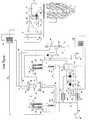
- FIG. 1 is a schematic illustration of a dehumidification plant according to the present invention.
- a dehumidification plant comprises one or more hoppers 2, in which granular material 1 to be dehumidified by means of a gas current, e. g. air, is loaded, and two towers 29, 36, in which the moisture of the air is adsorbed.
- the plastic granular material is dehumidified by the air, the two towers being alternately one in a processing phase (in which the tower is crossed by an air current to be dehumidified) and the other in a regeneration phase of the adsorbent material contained therein, as occurs with conventional plants.
- Each hopper 2 comprises an upper loading mouth 3a for the granular material 1 and a lower discharge mouth 3, at which a meter or extractor device is provided (not shown in the Figure) of any suitable type.
- an inlet mouth 48 is provided for hot and dry air, from which a duct 4 departs towards the interior of the hopper 2, duct 4 connecting the inlet mouth 48 with a diffuser 5, arranged in a lower zone of the hopper, a plurality of holes being provided in the diffuser through which hot and dry air is fed into the hopper and diffused in many directions, thereby hitting and thus dehumidifying any granular material descending along the hopper.
- each hopper comprises an upper air discharge mouth 47 which is in fluid communication with one end of a discharge duct 8, in which a temperature probe 49 is prearranged, electrically connected to an electronic control unit 46.
- the moist and hot air exiting from the hopper through the discharge duct 8 is first caused to pass through a filter 9, then, by means of a duct 10, through a heat exchanger 15 of any suitable type, for a pre-cooling thereof, and then by means of a duct 16, through a second filter 18.
- the air from the filter 18 is then further cooled through another heat exchanger 20 via a duct 19, whereby it is brought to a temperature suitable for its subsequent dehumidification, as described below.
- the dehumidification plant moreover comprises pressurization or air pumping means, e. g. comprising one or more blowers 23 equipped with rotation speed variation means 69 of any suitable type, preferably of electronic type, e. g. an inverter of any suitable type, which is designed to vary the supply frequency to the motor of the blower 23, thereby modulating the air flow rate intended for the tower in processing phase. It is with such rotation speed variation means that it is possible to significantly limit the heat energy consumptions.
- pressurization or air pumping means e. g. comprising one or more blowers 23 equipped with rotation speed variation means 69 of any suitable type, preferably of electronic type, e. g. an inverter of any suitable type, which is designed to vary the supply frequency to the motor of the blower 23, thereby modulating the air flow rate intended for the tower in processing phase. It is with such rotation speed variation means that it is possible to significantly limit the heat energy consumptions.
- the suction mouth of the blower 23 is connected in fluid communication with the outlet of the heat exchanger 20, whereas its delivery side is connected to a further heat exchanger 22 designed to cool the exhaust air that is heated by the motor of the blower 23.
- a second blower 24 can be advantageously provided, which is arranged in parallel with the blower 23, that is intended to maintain a minimum air flow rate value.
- the blower 24 can function at constant rotation speed or it too can be equipped with a rotation speed variation device 70.
- a bypass for the system formed by the exchangers 20 and 22 and by the blowers 23 and 24 can also be provided, such bypass comprising a duct 21 that departs from the duct 19, is in fluid communication with an air outlet duct from the exchanger 22, and is interceptable by a valve 21, whose opening/closing makes it possible to adjust the flow rate of air exiting from the filter 18 that is sent to the exchanger and blower system.
- a circuit can also be advantageously provided between the two exchangers 20, 22 for automatically adjusting the refrigerant flow throughout the heat exchangers. More particularly, the refrigerant fluid is fed to the exchangers 20, 22 through respective ducts 67, 75, and discharged from the exchangers through ducts 63, 64.
- the ducts 63, 64 lead to a duct 65, which conveys refrigerant liquid to an external cooling unit 68, from where the refrigerant liquid is supplied to the two exchangers via the duct 66, from which ducts 67, 75 depart.
- the ducts 67, 75 are preferably interceptable by a third adjusting means or valve 61, 62 of any suitable type, controllable by the electronic control unit 46.
- a temperature probe 74 is arranged that is electrically connected to the program control unit 46, while at one portion, in use the lower portion of a tower 29, 36, a respective temperature probe 30, 37 is provided. Temperature signals detected by the probe 74 and by the temperature probes 30, 37 of the tower 29, 36 in processing phase are sent to the electronic control unit 46, which controls the adjusting valves 61, 62, thereby adjusting the flow of the liquid refrigerant circulating in the heat exchangers, in order to obtain the desired temperature for the process air flow that crosses the heat exchangers 20, 22.
- the air brought to a pre-established temperature by the exchanger system 20-22 is conveyed through the duct 25 into a first air flow distribution device or second valve means 32, e. g. a slide valve actuated by a device 73 of any suitable type, e. g. a linear actuation device disclosed in the patent application IT-VR2006A000030-A in the name of the applicant of the present patent application.
- a first air flow distribution device or second valve means 32 e. g. a slide valve actuated by a device 73 of any suitable type, e. g. a linear actuation device disclosed in the patent application IT-VR2006A000030-A in the name of the applicant of the present patent application.
- One such device directs the flow into the ducts 26, 27, which alternately supply air to be dehumidified towards a respective dehumidification tower 29, 36, in each of which a respective set of absorbent materials or means 51, 52, e. g. molecular sieves, is provided.
- Air is inserted in the towers through an inlet mouth 53, 54 and is made to leave through an outlet mouth 55, 56.
- the air is made to pass through a respective heating means 28,35.
- the dehumidification towers 29, 36 can be of any suitable type, such as with coaxial structure, e. g. as taught in EP-1 475 593 .
- the humid air from the outlet of the hopper 2 is cooled by means of the exchangers 15 and possibly 20, 22 while flowing through the absorbent material 51 which almost completely absorbs the moisture of the saturated air.
- the air is made to leave though the mouth 55 and is fed via the duct 31 to the slide valve 32, from where the air via the duct 17 is supplied to an exchanger 15 set to pre-heat the air to be supplied to the hopper 2.
- the dehumidification plant comprises a heater 6, designed to heat the dry air pre-heated by the heat exchanger 15 and that fed by the duct 12 coming from the refrigeration cycle (this step will be further described below).
- the hot, dry air from the heater 6 is supplied through the duct 7 to the duct 4 in order to be fed to the hopper 2 through the diffuser 5, as explained above.
- a temperature sensor 50 is arranged on the duct 7, more specifically at the inlet mouth 48, such sensor being connected to the electronic control unit 46.
- a dehumidification plant according to the present invention also comprises a regeneration cycle for the adsorbent material as described below with reference to the drawings.
- the adsorbent material of the other tower 36 While the dehumidification tower 29 is in a processing phase and thus the air is supplied therein for being dehumidified, the adsorbent material of the other tower 36, which is connected in parallel with the tower 29, is regenerated by making hot air pass through it. Such hot air absorbs water molecules previously adsorbed in the adsorbent material 52 of the tower 36 in a preceding processing cycle.
- Regeneration of the towers is carried out by suctioning ambient air, which is made to pass through a filter 40 and then through a duct 41 and a first valve means, e. g. a slide valve 42, from which it is conveyed to the slide valve 32 via a duct 45 intercepted by a blower 44 equipped with a rotation speed variation device 71, e. g. an inverter, as described above. From here, the air is conveyed through the duct 27 to the tower 36, being preferably pre-heated to a pre-established temperature through the heater 35, which in this phase is turned on.
- a first valve means e. g. a slide valve 42
- a temperature probe 37 is provided at the lower portion (in use) of the tower 36, which is arranged to send an electric signal to the electronic control unit 46.
- the control unit adjusts the operating temperature of the heater 35 by means of a thermoregulation device of any suitable type (not shown in the drawings).
- the air is then fed to the adsorbent material 52, dehumidifying it, and then it is conveyed through the duct 33 to the slide valve 32, from where it is sent to the slide valve 42 that discharges a moisture-laden air flow into the environment through the discharge duct 43.
- the regeneration cycle is carried out until the adsorbent material 52 in the tower 36, now in regeneration phase, is nearly completely regenerated. At that point, the adsorbent material 52 is too hot to be used for dehumidifying the air exiting from the hopper 2.
- the slide valve 42 actuated by a control device 72 of any suitable type, e. g. the device described in the patent application IT-VR2006000030-A in the name of the applicant of the present invention, places the duct 45, intercepted by the blower 44, in fluid communication with a duct 39, which departs from the duct 17, and at the same time places the duct 38, through which the air flows that exits from the tower 36 now in regeneration phase, in fluid communication with the duct 11 that supplies the duct 12 upstream of the heater 6.
- a control device 72 of any suitable type, e. g. the device described in the patent application IT-VR2006000030-A in the name of the applicant of the present invention, places the duct 45, intercepted by the blower 44, in fluid communication with a duct 39, which departs from the duct 17, and at the same time places the duct 38, through which the air flows that exits from the tower 36 now in regeneration phase, in fluid communication with the duct 11 that supplies the duct 12 upstream of the
- the blower 44 no longer suctions air from the outside environment, saturated with water molecules, but rather draws it from the duct 17, into which the dry air flow from the other dehumidification tower is fed, which in this step is in processing conditions.
- the amount of dry air drawn by the main duct 17 is regulated by the rotation speed adjusting device 71 of the blower 44, which in turn is controlled by the electronic control unit 46.
- the heater 35 remains on until the regeneration of the absorbent means 52 of the regeneration tower 36 is completed.
- the air drawn by the duct 17, being at operating temperature and dehumidified is designed to cool the adsorbent material 52 made hot in the regeneration step.
- dehumidified air there occurs a lower contamination of said adsorbent means with respect to that which would be caused if air drawn directly from the environment is used, thus obtaining a significantly lower time interval between subsequent regeneration steps.
- the heat quantity transferred to the air entering the regeneration tower 36 is controlled by the temperature sensor 37 as well as the temperature detection means 58 located in the upper part of the tower 36, which send signals to the electronic control unit 46.
- the distribution devices 42 and 32 are also adjusted by the control unit 46.
- the actuation device 73 controls the slide valve 32 in order to start a regeneration phase in the tower 29 containing the adsorbent material by now saturated, and a processing phase in the tower 36 containing the regenerated adsorbent means at low temperature.
- a dehumidification plant according to the present invention also comprises measuring means of the air flow rate, e. g. Venturi meter nozzles 13 and 14 equipped with a respective differential pressure sensor, in the ducts 11 and 12, respectively, (such nozzles are not shown in the drawings and can be of any suitable type, for example as illustrated and described in the patent application IT-VR2005A000128 in the name of the applicant of the present application).
- measuring means of the air flow rate e. g. Venturi meter nozzles 13 and 14 equipped with a respective differential pressure sensor, in the ducts 11 and 12, respectively, (such nozzles are not shown in the drawings and can be of any suitable type, for example as illustrated and described in the patent application IT-VR2005A000128 in the name of the applicant of the present application).
- the Venturi meter nozzle 13 measures the dry air flow rate in the duct 11
- the Venturi meter nozzle 14 measures the dry air flow rate in the duct 12, and both send a signal to the electronic control unit 46, which - also on the base on the signals received by the temperature probes 49, 50 - controls the speed variation device 69 that modulates the rotation speed of the blower 23, whereby a so-called "closed ring" control is obtained between speed variator device, Venturi meters 13, 14, temperature probes 49, 50 and the electronic control unit 46, as well as the speed variator device 71 of the blower 44.
- a dry air flow rate directed to the hopper 2 as a function of the characteristics of the granular material 1 to be dehumidified, as well as a modulation of the flow rate of dry air discharged from the tower in heating and/or cooling phase.
- an overall flow rate of dry air entering the heater 6 given by the sum of the two flow rates of the ducts 11 and 12, thereby obtaining a much greater flexibility in the management of the overall flow rate of air intended to dehumidify the granular material 1 in the hopper 2.
- the dehumidification plant of the present invention can advantageously comprise a user interface 60, which typically comprises a video unit and data insertion means, e. g. a keyboard and a mouse.
- a user interface 60 typically comprises a video unit and data insertion means, e. g. a keyboard and a mouse.
- the user interface is a graphic object interface of "touch-screen" type.
- a table is pre-stored, which reports a list of a first array of granular plastic materials with their respective main treatment parameters, that is provided for use in the plant; in a second storage portion, the operator will store the parameters of the materials defined as "experimental" by using the user interface 60.
- the electronic control unit will calculate the air flow rate in processing phase and that in regeneration phase, sending an electric signal to the rotation speed variation devices of the air pumping or pressurization means 23, 24, 44.
- dehumidification towers are used of coaxial type, for example according to patent EP-1 475 593 , the heater 6 and the heat exchanger 15 can be omitted as a function of the type of material 1 to be dehumidified.
- a plant according to the present invention can also be used for dehumidifying granular materials of plastic material that require an inert atmosphere, thereby preserving the granular material from possible oxidizing reactions.
- the flow air circulating in the plant of the present invention can be substituted with inert gases, e. g. nitrogen, argon or another inert gas.
- dehumidification plant and process are described that use air as dehumidifying gas, but it will be clear for a man skilled in the art that another gas can also be used, such as nitrogen.
- three or more dehumidification towers can be used in parallel, to increase the performances of the plant according to the present invention.
Landscapes
- Engineering & Computer Science (AREA)
- Mechanical Engineering (AREA)
- Chemical & Material Sciences (AREA)
- General Engineering & Computer Science (AREA)
- Analytical Chemistry (AREA)
- General Chemical & Material Sciences (AREA)
- Oil, Petroleum & Natural Gas (AREA)
- Chemical Kinetics & Catalysis (AREA)
- Drying Of Gases (AREA)
- Solid-Sorbent Or Filter-Aiding Compositions (AREA)
- Fertilizers (AREA)
Claims (20)
- Installation de déshumidification pour un matériau granulaire, comprenant au moins une trémie (2) ayant au moins une bouche de chargement (3a) et une bouche d'évacuation (3) dudit matériau granulaire, au moins une bouche supérieure d'alimentation dans ladite au moins une trémie (2) et au moins une bouche inférieure de refoulement d'un milieu gazeux à partir de celle-ci, un moyen d'adsorption de l'humidité (51, 52) conçu pour adsorber l'humidité transmise par ledit milieu gazeux ; au moins deux tours (29, 36) agencées de manière à contenir ledit moyen adsorbants (51, 52) ; un moyen d'alimentation conçu pour transmettre ledit milieu gazeux à ladite au moins une trémie (2) et auxdites au moins deux tours (29, 36) ; au moins une unité de commande électronique (46) ; un moyen de détection conçu pour détecter des variables de procédé de ladite installation et relié électriquement à ladite au moins une unité de commande électronique (46), caractérisée en ce qu'elle comprend un moyen de distribution conçu pour distribuer le milieu gazeux déshumidifié provenant d'au moins une (29, 36) desdites au moins deux tours afin de le transmettre à au moins une autre tour (36, 29) parmi lesdites au moins deux tours, ledit moyen de distribution pouvant être commandé par ladite au moins une unité de commande électronique (46) entre au moins une position ouverte, dans laquelle au moins une partie dudit milieu gazeux déshumidifié contenu dans ladite au moins une desdites au moins deux tours (29, 36) est transmise à ladite au moins une autre (36, 29) desdites au moins deux tours, et au moins une position fermée, ledit moyen de distribution comprenant au moins un premier moyen formant soupape (42), au moins un conduit (45) destiné à placer ledit premier moyen formant soupape (42) en communication de fluide avec au moins une desdites au moins deux tours (29, 36), au moins un conduit (38) entre au moins une autre (36, 29) desdites au moins deux tours et ledit premier moyen formant soupape (42) et un moyen de mise en pression (44) pour ledit milieu gazeux déshumidifié, et en ce qu'elle comprend au moins un conduit d'émission dudit milieu gazeux déshumidifié (11) entre ledit premier moyen formant soupape (42) et ladite au moins une trémie (2).
- Installation selon la revendication 1, caractérisée en ce que le premier moyen formant soupape comprend un tiroir (42).
- Installation selon la revendication 1, caractérisée en ce que ledit moyen de mise en pression (44) dudit milieu gazeux comprend au moins une soufflante conçue pour intercepter ledit au moins un conduit (45) destiné à placer en communication de fluide ledit premier moyen formant soupape (42) et au moins une (29, 36) desdites au moins deux tours.
- Installation selon la revendication 3, caractérisée en ce que ledit moyen de distribution comprend au moins un dispositif de réglage (71) conçu pour régler la vitesse de rotation de ladite soufflante.
- Installation selon la revendication 4, caractérisée en ce que ledit dispositif de réglage (71) de la vitesse de rotation de ladite soufflante (44) peut être commandé par ladite au moins une unité de commande électronique (46).
- Installation selon l'une quelconque des revendications 1 à 5, caractérisée en ce que ledit moyen de détection de variables de procédé comprend au moins un capteur de température (37) réglé pour détecter la température d'une partie inférieure d'au moins une desdites au moins deux tours (29, 36).
- Installation selon l'une quelconque des revendications 1 à 5, caractérisée en ce que ledit moyen de détection de variables de procédé comprend au moins un capteur de température (58) réglé pour détecter la température d'une partie supérieure d'au moins une desdites au moins deux tours (29, 36).
- Installation selon l'une quelconque des revendications 1 à 7, caractérisée en ce que ledit moyen d'alimentation dudit milieu gazeux déshumidifié comprend au moins un second moyen formant soupape (32), au moins un conduit de refoulement (26, 27, 31, 33) de milieu gazeux déshumidifié entre ledit au moins un premier moyen formant soupape (42) et lesdites au moins deux tours (29, 36), et au moins un conduit de liaison de fluide (16, 25, 17, 12) entre ledit au moins un second moyen formant soupape (32) et ladite au moins une trémie (2), et en ce que ledit moyen de distribution comprend au moins un conduit (45) destiné à placer en communication de fluide ledit premier moyen formant soupape (42) et ledit au moins un second moyen formant soupape (32), et au moins un conduit (38) agencé de manière à placer en communication de fluide ledit premier moyen formant soupape (42) et ledit second moyen formant soupape (32).
- Installation selon la revendication 8, caractérisée en ce qu'elle comprend un dispositif d'actionnement (73) dudit second moyen formant soupape (32).
- Installation selon l'une quelconque des revendications précédentes, caractérisée en ce qu'elle comprend un moyen de chauffage et de refroidissement (6, 20, 22) dudit milieu gazeux réglé pour refroidir ou réchauffer ledit milieu gazeux alimenté entre ladite trémie (2) et au moins une desdites au moins deux tours (29, 36).
- Installation selon la revendication 10, caractérisée en ce qu'elle comprend au moins un conduit d'alimentation (11, 12) dudit milieu gazeux déshumidifié entre au moins une desdites au moins deux tours (29, 36) et le moyen de chauffage (6), un conduit de liaison (7) entre ledit moyen de chauffage (6) et ladite au moins une trémie (2), au moins un capteur de température (50) relié électriquement à ladite unité de commande électronique (46) et agencé de manière à détecter la température dudit conduit de liaison (7).
- Installation selon la revendication 10 ou 11, caractérisée en ce que ledit moyen de chauffage et de refroidissement du milieu gazeux comprend au moins un échangeur de chaleur (20, 22) conçu pour refroidir ledit milieu gazeux transmis entre ladite au moins une trémie (2) et lesdites au moins deux tours (29, 36), un moyen de mise en pression ou de pompage dudit milieu gazeux (23, 24), un moyen formant variateur (69, 70) agencé de manière à faire varier la vitesse de rotation dudit moyen de mise en pression ou de pompage, au moins une unité de réfrigération externe (68) pour un fluide frigorigène alimentant ledit au moins un échangeur de chaleur (20, 22).
- Installation selon la revendication 12, caractérisée en ce qu'elle comprend au moins un conduit de refoulement (67, 75) de fluide frigorigène de ladite unité de réfrigération externe (68) vers ledit au moins un échangeur de chaleur (20, 22), au moins un conduit de refoulement (63, 64) de fluide frigorigène dudit au moins un échangeur de chaleur (20, 22) vers ladite unité de réfrigération externe (68), au moins un troisième moyen formant soupape de réglage (61, 62) destiné à intercepter ledit au moins un conduit de refoulement (67, 75) de fluide frigorigène provenant de ladite unité de réfrigération externe (68) vers ledit au moins un échangeur de chaleur (20, 22), et/ou au moins un conduit d'émission (63, 64) de fluide frigorigène dudit au moins un échangeur de chaleur (20, 22) vers ladite au moins une unité de réfrigération externe (68), et un moyen d'actionnement de ladite au moins une soupape de réglage (61, 62) pouvant être commandé par ladite unité de commande électronique (46).
- Installation selon la revendication 12 ou 13, caractérisée en ce qu'elle comprend au moins une sonde de température (74) placée sur une bouche d'aspiration dudit moyen de mise en pression ou de pompage dudit milieu gazeux (23, 24).
- Installation de déshumidification selon l'une quelconque des revendications précédentes, caractérisée en ce qu'elle comprend un moyen de mesure conçu pour mesurer le débit dudit milieu gazeux déshumidifié (13, 14).
- Installation selon la revendication 15, caractérisée en ce que ledit moyen de mesure du débit comprend une buse de débitmètre Venturi (13, 14) pourvue d'un capteur de pression différentielle correspondant, et peut être relié électriquement à ladite au moins une unité de commande électronique (46).
- Installation selon l'une quelconque des revendications 1 à 16, caractérisée en ce que ledit moyen adsorbant comprend des tamis moléculaires.
- Installation selon l'une quelconque des revendications précédentes, caractérisée en ce qu'elle comprend une interface utilisateur (60) comprenant une unité vidéo et un moyen d'introduction de données, ladite interface utilisateur étant conçue pour stocker des paramètres et des caractéristiques de traitement liés aux matériaux granulaires devant être traités dans l'unité de commande électronique (46).
- Installation selon la revendication 18, caractérisée en ce que ladite unité de commande électronique (46) comprend une première partie stockage préliminaire d'une table, dans laquelle figure une liste d'une première gamme de matières plastiques granulaires conjointement avec les principaux paramètres de traitement correspondants que l'on prévoit d'utiliser dans l'installation, et une seconde partie stockage destinée à stocker les paramètres d'une seconde gamme de matières plastiques granulaires.
- Installation selon l'une quelconque des revendications précédentes, caractérisée en ce qu'elle comprend au moins un moyen de chauffage (28, 35) agencé en amont d'au moins une desdites au moins deux tours (29, 36).
Applications Claiming Priority (1)
| Application Number | Priority Date | Filing Date | Title |
|---|---|---|---|
| IT000074A ITVR20070074A1 (it) | 2007-05-25 | 2007-05-25 | Impianto e procedimento di deumidificazione a portata variabile per materiali granulari |
Publications (3)
| Publication Number | Publication Date |
|---|---|
| EP1995541A2 EP1995541A2 (fr) | 2008-11-26 |
| EP1995541A3 EP1995541A3 (fr) | 2009-06-17 |
| EP1995541B1 true EP1995541B1 (fr) | 2016-02-17 |
Family
ID=39713759
Family Applications (1)
| Application Number | Title | Priority Date | Filing Date |
|---|---|---|---|
| EP08156719.0A Not-in-force EP1995541B1 (fr) | 2007-05-25 | 2008-05-22 | Installation de déshumidification pour matériaux granulaires |
Country Status (5)
| Country | Link |
|---|---|
| US (1) | US8021462B2 (fr) |
| EP (1) | EP1995541B1 (fr) |
| KR (1) | KR20080103914A (fr) |
| CN (1) | CN101311654B (fr) |
| IT (1) | ITVR20070074A1 (fr) |
Families Citing this family (32)
| Publication number | Priority date | Publication date | Assignee | Title |
|---|---|---|---|---|
| ITVR20070140A1 (it) * | 2007-10-09 | 2009-04-10 | Moretto Spa | Unita' di trattamento di materiali granulari dotata di gruppo di recupero calore |
| IT1392943B1 (it) * | 2009-02-25 | 2012-04-02 | Moretto Spa | Metodo e impianto di deumidificazione di materiali in forma granulare |
| CA2782908C (fr) * | 2009-12-11 | 2016-02-09 | Edward Weisselberg | Appareil et procede pour lyophilisation continue |
| AT509273A1 (de) * | 2009-12-17 | 2011-07-15 | Wittmann Kunststoffgeraete | Einrichtung zur trocknung von schüttgut |
| IT1402783B1 (it) * | 2010-10-26 | 2013-09-18 | Moretto Spa | Metodo e impianto di deumidificazione di materiale in forma granulare. |
| CN104364646B (zh) * | 2011-12-20 | 2020-06-09 | 百瑞空气工程(亚洲)有限公司 | 用于水分确定和控制的方法和装置 |
| US10414083B2 (en) | 2014-02-20 | 2019-09-17 | Novatec, Inc. | Multiple sensor resin delivery optimizing vacuum pump operation |
| US10280015B2 (en) | 2014-02-20 | 2019-05-07 | Stephen B. Maguire | Method for adjustably restricting air flow and apparatus therefor |
| US10175701B2 (en) | 2014-02-20 | 2019-01-08 | Stephen B. Maguire | Air flow regulator with detector and method for regulating air flow |
| US9937651B2 (en) | 2014-02-20 | 2018-04-10 | Novatec, Inc. | Resin delivery apparatus and method with plural air flow limiters |
| US10144598B2 (en) | 2014-02-20 | 2018-12-04 | Novatec, Inc. | Variable frequency drive combined with flow limiter set for limiting flow to selected level above design choice |
| US10179708B2 (en) | 2014-02-20 | 2019-01-15 | Maguire Products, Inc. | Granular material delivery system with air flow limiter |
| US9826338B2 (en) | 2014-11-18 | 2017-11-21 | Prophecy Sensorlytics Llc | IoT-enabled process control and predective maintenance using machine wearables |
| US10131506B2 (en) | 2014-12-09 | 2018-11-20 | Maguire Products, Inc. | Selective matrix conveyance apparatus and methods for granular resin material |
| US20160245279A1 (en) | 2015-02-23 | 2016-08-25 | Biplab Pal | Real time machine learning based predictive and preventive maintenance of vacuum pump |
| US20160245686A1 (en) | 2015-02-23 | 2016-08-25 | Biplab Pal | Fault detection in rotor driven equipment using rotational invariant transform of sub-sampled 3-axis vibrational data |
| US10481195B2 (en) | 2015-12-02 | 2019-11-19 | Machinesense, Llc | Distributed IoT based sensor analytics for power line diagnosis |
| US10599982B2 (en) | 2015-02-23 | 2020-03-24 | Machinesense, Llc | Internet of things based determination of machine reliability and automated maintainenace, repair and operation (MRO) logs |
| US10648735B2 (en) | 2015-08-23 | 2020-05-12 | Machinesense, Llc | Machine learning based predictive maintenance of a dryer |
| US10613046B2 (en) | 2015-02-23 | 2020-04-07 | Machinesense, Llc | Method for accurately measuring real-time dew-point value and total moisture content of a material |
| US10638295B2 (en) | 2015-01-17 | 2020-04-28 | Machinesense, Llc | System and method for turbomachinery preventive maintenance and root cause failure determination |
| US20160313216A1 (en) | 2015-04-25 | 2016-10-27 | Prophecy Sensors, Llc | Fuel gauge visualization of iot based predictive maintenance system using multi-classification based machine learning |
| US10179696B2 (en) | 2015-01-27 | 2019-01-15 | Novatec, Inc. | Variable opening slide gate for regulating material flow into airstream |
| US10138076B2 (en) | 2015-02-25 | 2018-11-27 | Stephen B. Maguire | Method for resin delivery including metering introduction of external air to maintain desired vacuum level |
| US9823289B2 (en) | 2015-06-01 | 2017-11-21 | Prophecy Sensorlytics Llc | Automated digital earth fault system |
| US10921792B2 (en) | 2017-12-21 | 2021-02-16 | Machinesense Llc | Edge cloud-based resin material drying system and method |
| CN108362122A (zh) * | 2018-05-23 | 2018-08-03 | 宁波诺博特机械有限公司 | 一种物料干燥除湿设备 |
| CN109186247A (zh) * | 2018-09-11 | 2019-01-11 | 广东申菱环境系统股份有限公司 | 一种水源节能型热泵干燥系统 |
| CN109556386A (zh) * | 2018-11-09 | 2019-04-02 | 广东申菱环境系统股份有限公司 | 一种节能型热泵干燥系统 |
| IT202000007147A1 (it) * | 2020-04-03 | 2021-10-03 | Piovan Spa | Apparato e Metodo di Trattamento di Materiale Incoerente |
| IT202100031625A1 (it) * | 2021-12-17 | 2023-06-17 | Piovan Spa | Apparato e Metodo di Riduzione dell’Odore |
| IT202100033110A1 (it) * | 2021-12-30 | 2023-06-30 | Piovan Spa | Apparato e metodo di trattamento per materiale plastico incoerente |
Family Cites Families (22)
| Publication number | Priority date | Publication date | Assignee | Title |
|---|---|---|---|---|
| US3621585A (en) * | 1969-10-31 | 1971-11-23 | Joseph D Robertson | Materials dryer |
| US3850592A (en) * | 1972-11-24 | 1974-11-26 | Deltech Eng Inc | Heat pump dryer |
| US4023940A (en) * | 1975-07-02 | 1977-05-17 | Whitlock, Inc. | Regeneration cycle control for industrial air dryer |
| DE3131471A1 (de) * | 1981-03-20 | 1982-09-30 | Roderich Wilhelm Dr.-Ing. 6100 Darmstadt Gräff | Vorrichtung zum trocknen feuchter abluft aus einem oder mehreren schuettgut-trocknungsbehaeltern |
| US4509272A (en) * | 1981-03-20 | 1985-04-09 | Graeff Roderich Wilhelm | Method and apparatus for drying moist exhaust air from one or more bulk material drying hoppers |
| DE3336048C2 (de) * | 1983-10-04 | 1985-08-29 | Klaus 8066 Bergkirchen Oschmann | Verfahren und Vorrichtung zum Entfeuchten eines Trockengases |
| JPS60114511A (ja) * | 1983-11-25 | 1985-06-21 | Sumitomo Metal Ind Ltd | 高炉の送風流量制御方法 |
| EP0416944A1 (fr) * | 1989-09-08 | 1991-03-13 | W.R. Grace & Co.-Conn. | Système de séchage infrarouge |
| US4974337A (en) * | 1989-10-30 | 1990-12-04 | The Conair Group, Inc. | Apparatus and method of drying and dehumidifying plastic |
| US5768897A (en) * | 1992-06-16 | 1998-06-23 | Universal Dynamics Corporation | Air drying apparatus and method with high ratio gas flow to absorber weight |
| US5546673A (en) * | 1995-05-19 | 1996-08-20 | The Conair Group, Inc. | Plastic pellet dryer control system equipped with a temperature protection device for the heating unit |
| US5779768A (en) * | 1996-03-19 | 1998-07-14 | Air Products And Chemicals, Inc. | Recovery of volatile organic compounds from gas streams |
| US5846295A (en) * | 1997-03-07 | 1998-12-08 | Air Products And Chemicals, Inc. | Temperature swing adsorption |
| DE19719483A1 (de) * | 1997-05-07 | 1998-11-12 | Motan Holding Gmbh | Trocknungsanlage |
| US5926969A (en) * | 1997-06-13 | 1999-07-27 | Universal Dynamics, Inc. | Method and apparatus for regenerating a moist absorption medium |
| US6289606B2 (en) * | 1997-06-13 | 2001-09-18 | Novatec, Inc. | Apparatus and method for moisture control of particulate material |
| DE60123374T3 (de) * | 2001-01-25 | 2012-05-16 | Air Products And Chemicals, Inc. | Verfahren zum Betrieb eines Temperaturwechsel-Adsorptionssystems und entsprechende Vorrichtung |
| ITPD20010251A1 (it) * | 2001-10-25 | 2003-04-25 | Piovan Spa | Dispositivo per l'ottimizzazione di impianti di deumidificazione di granuli plastici. |
| ITPD20010278A1 (it) * | 2001-11-28 | 2003-05-28 | Plastic Systems Srl | Procedimento ed impianto di deumidificazione di materie plastiche, inparticolare resine poliestere. |
| ITVR20030053A1 (it) * | 2003-05-05 | 2004-11-06 | Moretto Plastics Automation S R L | Apparecchiatura ed impianto di deumidificazione a setacci molecolari |
| ITVR20040162A1 (it) * | 2004-10-19 | 2005-01-19 | Moretto Plastics Automation Srl | Deumidificatore ad adsorbimento per granuli di materiale plastico |
| ITVR20060030A1 (it) * | 2006-02-10 | 2007-08-11 | Moretto Spa | Impianto e procedimento di deumidificazione a funzionamento flessibile particolarmente per materiali granulari. |
-
2007
- 2007-05-25 IT IT000074A patent/ITVR20070074A1/it unknown
-
2008
- 2008-05-22 EP EP08156719.0A patent/EP1995541B1/fr not_active Not-in-force
- 2008-05-23 US US12/153,784 patent/US8021462B2/en not_active Expired - Fee Related
- 2008-05-23 KR KR1020080047881A patent/KR20080103914A/ko not_active Withdrawn
- 2008-05-23 CN CN2008100982230A patent/CN101311654B/zh not_active Expired - Fee Related
Also Published As
| Publication number | Publication date |
|---|---|
| EP1995541A2 (fr) | 2008-11-26 |
| ITVR20070074A1 (it) | 2008-11-26 |
| CN101311654B (zh) | 2013-06-05 |
| CN101311654A (zh) | 2008-11-26 |
| KR20080103914A (ko) | 2008-11-28 |
| EP1995541A3 (fr) | 2009-06-17 |
| US8021462B2 (en) | 2011-09-20 |
| US20080295354A1 (en) | 2008-12-04 |
Similar Documents
| Publication | Publication Date | Title |
|---|---|---|
| EP1995541B1 (fr) | Installation de déshumidification pour matériaux granulaires | |
| JP5905190B2 (ja) | 粒状物質の脱湿法及びそのプラント | |
| CN101772685B (zh) | 粉粒体材料的除湿干燥方法及粉粒体材料的除湿干燥系统 | |
| US5172489A (en) | Plastic resin drying apparatus and method | |
| US5688305A (en) | Method and device for drying of moist gases | |
| US6289606B2 (en) | Apparatus and method for moisture control of particulate material | |
| US7007402B1 (en) | System and method for drying particulate materials using heated gas | |
| CN100587376C (zh) | 用于塑料材料颗粒的吸附干燥器 | |
| US20070199203A1 (en) | Dehumidification method and plant particularly for granular materials | |
| JP4546215B2 (ja) | 乾燥ホッパにおける粒状物を通過するガス流量制御方法及び装置 | |
| CN102455114A (zh) | 颗粒状材料的脱水方法和设备 | |
| JPH0379052B2 (fr) | ||
| CN112387083B (zh) | 压缩气体的干燥机、压缩机设备及干燥压缩气体的方法 | |
| JP7528192B2 (ja) | 圧縮ガスのための乾燥機、乾燥機を備えた圧縮機設備、及び圧縮ガスの乾燥方法 | |
| CA2412772C (fr) | Systeme, appareil et procede permettant de reduire le contenu humide d'un materiau particulaire | |
| JP2002504034A (ja) | 粒状材料の水分調整用装置および方法 | |
| JP2015038392A (ja) | 乾燥装置 |
Legal Events
| Date | Code | Title | Description |
|---|---|---|---|
| PUAI | Public reference made under article 153(3) epc to a published international application that has entered the european phase |
Free format text: ORIGINAL CODE: 0009012 |
|
| AK | Designated contracting states |
Kind code of ref document: A2 Designated state(s): AT BE BG CH CY CZ DE DK EE ES FI FR GB GR HR HU IE IS IT LI LT LU LV MC MT NL NO PL PT RO SE SI SK TR |
|
| AX | Request for extension of the european patent |
Extension state: AL BA MK RS |
|
| PUAL | Search report despatched |
Free format text: ORIGINAL CODE: 0009013 |
|
| AK | Designated contracting states |
Kind code of ref document: A3 Designated state(s): AT BE BG CH CY CZ DE DK EE ES FI FR GB GR HR HU IE IS IT LI LT LU LV MC MT NL NO PL PT RO SE SI SK TR |
|
| AX | Request for extension of the european patent |
Extension state: AL BA MK RS |
|
| 17P | Request for examination filed |
Effective date: 20091216 |
|
| AKX | Designation fees paid |
Designated state(s): AT BE BG CH CY CZ DE DK EE ES FI FR GB GR HR HU IE IS IT LI LT LU LV MC MT NL NO PL PT RO SE SI SK TR |
|
| 17Q | First examination report despatched |
Effective date: 20100311 |
|
| GRAP | Despatch of communication of intention to grant a patent |
Free format text: ORIGINAL CODE: EPIDOSNIGR1 |
|
| INTG | Intention to grant announced |
Effective date: 20150826 |
|
| GRAS | Grant fee paid |
Free format text: ORIGINAL CODE: EPIDOSNIGR3 |
|
| GRAA | (expected) grant |
Free format text: ORIGINAL CODE: 0009210 |
|
| AK | Designated contracting states |
Kind code of ref document: B1 Designated state(s): AT BE BG CH CY CZ DE DK EE ES FI FR GB GR HR HU IE IS IT LI LT LU LV MC MT NL NO PL PT RO SE SI SK TR |
|
| REG | Reference to a national code |
Ref country code: GB Ref legal event code: FG4D |
|
| REG | Reference to a national code |
Ref country code: CH Ref legal event code: EP |
|
| REG | Reference to a national code |
Ref country code: IE Ref legal event code: FG4D |
|
| REG | Reference to a national code |
Ref country code: AT Ref legal event code: REF Ref document number: 775841 Country of ref document: AT Kind code of ref document: T Effective date: 20160315 |
|
| REG | Reference to a national code |
Ref country code: DE Ref legal event code: R096 Ref document number: 602008042358 Country of ref document: DE |
|
| REG | Reference to a national code |
Ref country code: CH Ref legal event code: NV Representative=s name: JACOBACCI AND PARTNERS SA, CH |
|
| REG | Reference to a national code |
Ref country code: FR Ref legal event code: PLFP Year of fee payment: 9 |
|
| REG | Reference to a national code |
Ref country code: NL Ref legal event code: MP Effective date: 20160217 |
|
| REG | Reference to a national code |
Ref country code: LT Ref legal event code: MG4D |
|
| PG25 | Lapsed in a contracting state [announced via postgrant information from national office to epo] |
Ref country code: FI Free format text: LAPSE BECAUSE OF FAILURE TO SUBMIT A TRANSLATION OF THE DESCRIPTION OR TO PAY THE FEE WITHIN THE PRESCRIBED TIME-LIMIT Effective date: 20160217 Ref country code: GR Free format text: LAPSE BECAUSE OF FAILURE TO SUBMIT A TRANSLATION OF THE DESCRIPTION OR TO PAY THE FEE WITHIN THE PRESCRIBED TIME-LIMIT Effective date: 20160518 Ref country code: NO Free format text: LAPSE BECAUSE OF FAILURE TO SUBMIT A TRANSLATION OF THE DESCRIPTION OR TO PAY THE FEE WITHIN THE PRESCRIBED TIME-LIMIT Effective date: 20160517 Ref country code: ES Free format text: LAPSE BECAUSE OF FAILURE TO SUBMIT A TRANSLATION OF THE DESCRIPTION OR TO PAY THE FEE WITHIN THE PRESCRIBED TIME-LIMIT Effective date: 20160217 |
|
| PGFP | Annual fee paid to national office [announced via postgrant information from national office to epo] |
Ref country code: GB Payment date: 20160520 Year of fee payment: 9 Ref country code: CH Payment date: 20160513 Year of fee payment: 9 |
|
| PG25 | Lapsed in a contracting state [announced via postgrant information from national office to epo] |
Ref country code: LV Free format text: LAPSE BECAUSE OF FAILURE TO SUBMIT A TRANSLATION OF THE DESCRIPTION OR TO PAY THE FEE WITHIN THE PRESCRIBED TIME-LIMIT Effective date: 20160217 Ref country code: PL Free format text: LAPSE BECAUSE OF FAILURE TO SUBMIT A TRANSLATION OF THE DESCRIPTION OR TO PAY THE FEE WITHIN THE PRESCRIBED TIME-LIMIT Effective date: 20160217 Ref country code: SE Free format text: LAPSE BECAUSE OF FAILURE TO SUBMIT A TRANSLATION OF THE DESCRIPTION OR TO PAY THE FEE WITHIN THE PRESCRIBED TIME-LIMIT Effective date: 20160217 Ref country code: LT Free format text: LAPSE BECAUSE OF FAILURE TO SUBMIT A TRANSLATION OF THE DESCRIPTION OR TO PAY THE FEE WITHIN THE PRESCRIBED TIME-LIMIT Effective date: 20160217 Ref country code: NL Free format text: LAPSE BECAUSE OF FAILURE TO SUBMIT A TRANSLATION OF THE DESCRIPTION OR TO PAY THE FEE WITHIN THE PRESCRIBED TIME-LIMIT Effective date: 20160217 Ref country code: BE Free format text: LAPSE BECAUSE OF NON-PAYMENT OF DUE FEES Effective date: 20160531 Ref country code: PT Free format text: LAPSE BECAUSE OF FAILURE TO SUBMIT A TRANSLATION OF THE DESCRIPTION OR TO PAY THE FEE WITHIN THE PRESCRIBED TIME-LIMIT Effective date: 20160617 |
|
| PGFP | Annual fee paid to national office [announced via postgrant information from national office to epo] |
Ref country code: FR Payment date: 20160525 Year of fee payment: 9 Ref country code: AT Payment date: 20160525 Year of fee payment: 9 Ref country code: IT Payment date: 20160518 Year of fee payment: 9 |
|
| PG25 | Lapsed in a contracting state [announced via postgrant information from national office to epo] |
Ref country code: DK Free format text: LAPSE BECAUSE OF FAILURE TO SUBMIT A TRANSLATION OF THE DESCRIPTION OR TO PAY THE FEE WITHIN THE PRESCRIBED TIME-LIMIT Effective date: 20160217 Ref country code: EE Free format text: LAPSE BECAUSE OF FAILURE TO SUBMIT A TRANSLATION OF THE DESCRIPTION OR TO PAY THE FEE WITHIN THE PRESCRIBED TIME-LIMIT Effective date: 20160217 |
|
| PGFP | Annual fee paid to national office [announced via postgrant information from national office to epo] |
Ref country code: DE Payment date: 20160729 Year of fee payment: 9 |
|
| REG | Reference to a national code |
Ref country code: DE Ref legal event code: R097 Ref document number: 602008042358 Country of ref document: DE |
|
| PG25 | Lapsed in a contracting state [announced via postgrant information from national office to epo] |
Ref country code: CZ Free format text: LAPSE BECAUSE OF FAILURE TO SUBMIT A TRANSLATION OF THE DESCRIPTION OR TO PAY THE FEE WITHIN THE PRESCRIBED TIME-LIMIT Effective date: 20160217 Ref country code: SK Free format text: LAPSE BECAUSE OF FAILURE TO SUBMIT A TRANSLATION OF THE DESCRIPTION OR TO PAY THE FEE WITHIN THE PRESCRIBED TIME-LIMIT Effective date: 20160217 Ref country code: RO Free format text: LAPSE BECAUSE OF FAILURE TO SUBMIT A TRANSLATION OF THE DESCRIPTION OR TO PAY THE FEE WITHIN THE PRESCRIBED TIME-LIMIT Effective date: 20160217 |
|
| PLBE | No opposition filed within time limit |
Free format text: ORIGINAL CODE: 0009261 |
|
| STAA | Information on the status of an ep patent application or granted ep patent |
Free format text: STATUS: NO OPPOSITION FILED WITHIN TIME LIMIT |
|
| PG25 | Lapsed in a contracting state [announced via postgrant information from national office to epo] |
Ref country code: LU Free format text: LAPSE BECAUSE OF FAILURE TO SUBMIT A TRANSLATION OF THE DESCRIPTION OR TO PAY THE FEE WITHIN THE PRESCRIBED TIME-LIMIT Effective date: 20160522 |
|
| 26N | No opposition filed |
Effective date: 20161118 |
|
| REG | Reference to a national code |
Ref country code: IE Ref legal event code: MM4A |
|
| PG25 | Lapsed in a contracting state [announced via postgrant information from national office to epo] |
Ref country code: BG Free format text: LAPSE BECAUSE OF FAILURE TO SUBMIT A TRANSLATION OF THE DESCRIPTION OR TO PAY THE FEE WITHIN THE PRESCRIBED TIME-LIMIT Effective date: 20160517 Ref country code: SI Free format text: LAPSE BECAUSE OF FAILURE TO SUBMIT A TRANSLATION OF THE DESCRIPTION OR TO PAY THE FEE WITHIN THE PRESCRIBED TIME-LIMIT Effective date: 20160217 |
|
| PG25 | Lapsed in a contracting state [announced via postgrant information from national office to epo] |
Ref country code: IE Free format text: LAPSE BECAUSE OF NON-PAYMENT OF DUE FEES Effective date: 20160522 |
|
| PG25 | Lapsed in a contracting state [announced via postgrant information from national office to epo] |
Ref country code: BE Free format text: LAPSE BECAUSE OF FAILURE TO SUBMIT A TRANSLATION OF THE DESCRIPTION OR TO PAY THE FEE WITHIN THE PRESCRIBED TIME-LIMIT Effective date: 20160217 |
|
| REG | Reference to a national code |
Ref country code: DE Ref legal event code: R119 Ref document number: 602008042358 Country of ref document: DE |
|
| REG | Reference to a national code |
Ref country code: BE Ref legal event code: MM Effective date: 20160531 |
|
| REG | Reference to a national code |
Ref country code: CH Ref legal event code: PL |
|
| REG | Reference to a national code |
Ref country code: AT Ref legal event code: MM01 Ref document number: 775841 Country of ref document: AT Kind code of ref document: T Effective date: 20170522 |
|
| GBPC | Gb: european patent ceased through non-payment of renewal fee |
Effective date: 20170522 |
|
| PG25 | Lapsed in a contracting state [announced via postgrant information from national office to epo] |
Ref country code: AT Free format text: LAPSE BECAUSE OF NON-PAYMENT OF DUE FEES Effective date: 20170522 |
|
| PG25 | Lapsed in a contracting state [announced via postgrant information from national office to epo] |
Ref country code: LI Free format text: LAPSE BECAUSE OF NON-PAYMENT OF DUE FEES Effective date: 20170531 Ref country code: CH Free format text: LAPSE BECAUSE OF NON-PAYMENT OF DUE FEES Effective date: 20170531 |
|
| REG | Reference to a national code |
Ref country code: FR Ref legal event code: ST Effective date: 20180131 |
|
| PG25 | Lapsed in a contracting state [announced via postgrant information from national office to epo] |
Ref country code: DE Free format text: LAPSE BECAUSE OF NON-PAYMENT OF DUE FEES Effective date: 20171201 Ref country code: GB Free format text: LAPSE BECAUSE OF NON-PAYMENT OF DUE FEES Effective date: 20170522 |
|
| PG25 | Lapsed in a contracting state [announced via postgrant information from national office to epo] |
Ref country code: FR Free format text: LAPSE BECAUSE OF NON-PAYMENT OF DUE FEES Effective date: 20170531 Ref country code: HU Free format text: LAPSE BECAUSE OF FAILURE TO SUBMIT A TRANSLATION OF THE DESCRIPTION OR TO PAY THE FEE WITHIN THE PRESCRIBED TIME-LIMIT; INVALID AB INITIO Effective date: 20080522 Ref country code: IT Free format text: LAPSE BECAUSE OF NON-PAYMENT OF DUE FEES Effective date: 20170522 Ref country code: CY Free format text: LAPSE BECAUSE OF FAILURE TO SUBMIT A TRANSLATION OF THE DESCRIPTION OR TO PAY THE FEE WITHIN THE PRESCRIBED TIME-LIMIT Effective date: 20160217 |
|
| PG25 | Lapsed in a contracting state [announced via postgrant information from national office to epo] |
Ref country code: IS Free format text: LAPSE BECAUSE OF FAILURE TO SUBMIT A TRANSLATION OF THE DESCRIPTION OR TO PAY THE FEE WITHIN THE PRESCRIBED TIME-LIMIT Effective date: 20160217 Ref country code: HR Free format text: LAPSE BECAUSE OF FAILURE TO SUBMIT A TRANSLATION OF THE DESCRIPTION OR TO PAY THE FEE WITHIN THE PRESCRIBED TIME-LIMIT Effective date: 20160217 Ref country code: MT Free format text: LAPSE BECAUSE OF NON-PAYMENT OF DUE FEES Effective date: 20160531 Ref country code: TR Free format text: LAPSE BECAUSE OF FAILURE TO SUBMIT A TRANSLATION OF THE DESCRIPTION OR TO PAY THE FEE WITHIN THE PRESCRIBED TIME-LIMIT Effective date: 20160217 Ref country code: MC Free format text: LAPSE BECAUSE OF FAILURE TO SUBMIT A TRANSLATION OF THE DESCRIPTION OR TO PAY THE FEE WITHIN THE PRESCRIBED TIME-LIMIT Effective date: 20160217 |
|
| REG | Reference to a national code |
Ref country code: AT Ref legal event code: UEP Ref document number: 775841 Country of ref document: AT Kind code of ref document: T Effective date: 20160217 |