EP1995589A2 - Rissdetektor für ein Drahtseil - Google Patents
Rissdetektor für ein Drahtseil Download PDFInfo
- Publication number
- EP1995589A2 EP1995589A2 EP08009385A EP08009385A EP1995589A2 EP 1995589 A2 EP1995589 A2 EP 1995589A2 EP 08009385 A EP08009385 A EP 08009385A EP 08009385 A EP08009385 A EP 08009385A EP 1995589 A2 EP1995589 A2 EP 1995589A2
- Authority
- EP
- European Patent Office
- Prior art keywords
- detection means
- magnetic detection
- wire
- rope
- magnetic
- Prior art date
- Legal status (The legal status is an assumption and is not a legal conclusion. Google has not performed a legal analysis and makes no representation as to the accuracy of the status listed.)
- Granted
Links
Images



Classifications
-
- G—PHYSICS
- G01—MEASURING; TESTING
- G01N—INVESTIGATING OR ANALYSING MATERIALS BY DETERMINING THEIR CHEMICAL OR PHYSICAL PROPERTIES
- G01N27/00—Investigating or analysing materials by the use of electric, electrochemical, or magnetic means
- G01N27/72—Investigating or analysing materials by the use of electric, electrochemical, or magnetic means by investigating magnetic variables
- G01N27/82—Investigating or analysing materials by the use of electric, electrochemical, or magnetic means by investigating magnetic variables for investigating the presence of flaws
- G01N27/83—Investigating or analysing materials by the use of electric, electrochemical, or magnetic means by investigating magnetic variables for investigating the presence of flaws by investigating stray magnetic fields
- G01N27/87—Investigating or analysing materials by the use of electric, electrochemical, or magnetic means by investigating magnetic variables for investigating the presence of flaws by investigating stray magnetic fields using probes
Definitions
- the present invention relates to a flaw detector of a wire-rope, capable of detecting a damage such as a breakage or the like of a strand in a wire-rope in a used condition without removal of the wire-rope from any of various facilities which utilize wire-ropes, in order to ensure a safety for the facility.
- Wire ropes which are used for an elevator, a lift, a cable car, a crane and the like have a risk of successive fracture of steel wires as constitutional elements of the wire-rope, due to its fatigue or abrasion, the degree of the fracture increasing with time due to aging effect. If the degree of the fracture exceeds a predetermined value, it is determined that the service life of the wire-rope has been expired, and accordingly, the wire-rope is replaced with new one. Thus, a periodical inspection has to be carried out so as to measure a degree of fracture of steel wires in order to evaluate whether the wire-rope is still used in safety or not.
- Patent Document 1 JP-A-7-198684 , page 7 and Fig. 1
- a portable flaw detector a wire-rope tester
- an electromagnetic flaw detection process for quantitatively measure a degree of fracture of a wire-rope, which is capable of facilitating a maintenance service for a wire-rope which is laid along the ceiling of a building at a higher level, as used for a crane or the like, or in particular for a wire-rope laid in a narrow inspection space within, for example, an elevator, wherein the wire-rope is magnetized in its longitudinal direction by using a set of permanent magnets, and probe coils for detecting a magnetic flux leaking from steel wires are arranged among the permanent magnets so as to inspect a breakage of the steel wire.
- Patent Document 2 JP-A-2002-5896 , page 8 and Fig. 2
- Patent Document 2 JP-A-2002-5896 , page 8 and Fig. 2
- the presence of a fracture of a steel wire is determined in view of the presence of a peak in an output waveform obtained by a magnetic detection means.
- the position of a fracture of a wire steel is located in the inward part of a wire-rope, the distance between the position of the fracture and the magnetic sensor is long, and according, an output from a magnetic sensor is low.
- it is required to incorporate several A/D converters in the magnetic detection means.
- calibration is required for the respective A/D converters.
- the present invention is directed to solve the above-mentioned conventional problems, and accordingly, an object of the present invention is to provide a flaw detector of a wire-rope, which can enhance the reliability of measurement even though a fracture is present in a deep part of the wire-rope.
- Another object of the present invention is to provide a flaw detector of a wire-rope, which can reduce calibration working so as to be easily handled.
- a flaw detector of a wire-rope in which a magnetic flux is introduced through a wire-rope composed of a plurality of inter-twisted steel wires in the longitudinal direction thereof so as to detect a leakage flux caused in a damaged part of the steel wires, incorporating a magnetizer for magnetizing the wire-rope in the longitudinal direction thereof, a plurality of magnetic detection means arranged in the circumferential direction of the wire-rope, for detecting the leakage magnetic flux, a storage in which several relationships among at least two of the group depths of the damaged parts, degrees of damage, sums of values detected by the plurality of magnetic detection means and difference values detected by the magnetic detection means, have been previously stored, wherein a depth and/or a degree of damage of the damaged part are obtained from the values detected by the magnetic detection means and the values stored in the storage.
- the depth and the degree of damage of the damaged part can be obtained through the relationships among the values detected by the plurality of magnetic detection means arranged in the circumferential direction of a wire-rope, and the depths and the degrees of damage of the damaged parts which haven been previously stored in the storage, thereby it is possible to enhance the reliability.
- Fig. 1 shows the configuration of a flaw detector of a wire-rope 1.
- a magnetizer 2 is arranged so as to magnetize a wire-rope 1 in the longitudinal direction of the latter.
- a plurality of magnetic detection means coil and magnetic sensors
- a first magnetic detection means 3 for detecting a magnetic flux laid along the entire periphery of the wire-rope 1
- a plurality of second magnetic detection means 4a to 4h and a plurality of third magnetic detection means 4a to 4h which are arranged in ring-like shapes and which are adjacent to one another along the entire periphery of the wire-rope 1.
- the second magnetic detection means 4a to 4h and the third magnetic detection means are shifted in their phases from each other by 90 deg., that is, the magnetic detection means 4i spans in its intermediate part between the magnetic detection means 4a and 4b, 4j between 4b and 4c, similarly, 4k to 4p between 4a to 4h, respectively.
- An output from the first magnetic detection means 3 is delivered to a total meter 5, and outputs from the second magnetic detection means 4a to 4h and the third magnetic detection means 4i to 4p are delivered to a difference meter 6.
- A/D conversion for input signals are carried out in the total meter 5 and the difference meter 6.
- Signals after the conversion are delivered into a second CPU 7 for calculating a ratio between signals from the difference meter 6 and the total meter 5, and delivers a signal exhibiting a depth of damage based upon values of depths of damage with respect to signal ratios, which are stored in a storage 8, to a display unit 11.
- a second CPU 9 calculates a degree of damage from a signal from the total meter 6, a signal from the difference meter 6, and data of threshold values stored in the storage for diagnosis.
- a difference between outputs from the magnetic detection means 4a, 4b is about 98 %.
- the deeper the damaged part in the wire-rope the smaller the difference in output between the magnetic detection means near the damaged part, and the magnetic detection means adjacent to the former means, that is, for example, the difference in output is 71 % if the distance from the damaged part to the center of the wire-rope is 4 mm, while the difference in output is 27 % if the distance from the damaged part to the center is 2 mm.
- the depth of the damaged part can be calculated by the first difference meter 6.
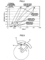
- Fig. 2 shows examples in the cases that, as to the relationship between a ratio of a difference value and a total value, and the total value, the damaged values (the number of damaged parts) are 1 and 2, and the distance from the damaged part to the center of the rope are 2 mm, 4 mm and 6 mm.
- the sum of the absolute value of a difference from the second detection means and the absolute of a difference value from the third detection means is used as the difference value.
- a threshold value is set at an intermediate position between the damaged value 1 and the damaged value 2, and it is diagnosed that the degree of damage is not less than 2 if the degree of damage exceeds the threshold value. Further, it is diagnosed that the degree of damage is 0 if the degree of damage is less than a noise level which has been previously obtained through experiments or the like.
- the storage 10 has been stored therein with threshold values and values of noise levels, as stated above, and the second CPU 9 delivers the damaged value to the display unit 11.
- the storages 8, 10 may be stored therein with, for example, relationships among depths of damage, total values and difference values, from which a depth of damage and a degree of damage may be obtained.
- the difference value becomes 0 at this time.
- the third detection means 4i to 4p the damaged part is located at the center of the magnetic detection means 4i.
- difference values are obtained from outputs from the magnetic detection means 4i to 4p.
- the third detection means are located, intermediate of the second detection means 4a to 4h in order to obtain difference values from the outputs from the third detection means even though the difference values of the output from the second detection means becomes 0.
- eight magnetic detection means are provided in total as the second magnetic means 4a to 4h and the third detection means 4i to 4p, respectively.
- the difference in output between a magnetic detection means 4y which delivers a peak value and a magnetic detection means 4x or 4z, which is adjacent thereto becomes about 98 %. Meanwhile, if the number of the magnetic detection means is 72, a difference in output between the magnetic detection means 4y which delivers a peak value, and the magnetic detection means 4x or 4z which is adjacent thereto becomes about 33 %.
- the difference in output between a magnetic detection means which delivers a peak output value, and a magnetic detection means which is adjacent thereto becomes largest while the difference in output between the other magnetic detection means becomes small, and accordingly, no diagnosis can be made if no difference in output between the magnetic detection means which delivers a peak output and the magnetic detection means which is adjacent to the former obtained can be obtained.
- the peak output is set to a value which is at least larger than two times as large as the output from the adjacent magnetic detection means.
- a total number of the magnetic detection means is calculated from the positional relationships between the damaged part and the magnetic detection means, as shown in Fig. 3 , and the relationship among magnitudes of magnetic fluxes.
- the number of the second magnetic detection means has to be set to at least two since a difference value should be obtained therefrom. If the damaged part 12 is located at the center of the magnetic detection means 4x, the damaged part 12 is longer from the magnetic distance 4y. In this case, the magnetic fluxes of the magnetic detection means 4x, 4y at their centers are different from each other, and accordingly, the difference value can be obtained, literally.
- the number of the respective first and second magnetic means is set to be preferably not less than two.
- the smaller the number of the magnetic detection means the wider the area in which a leakage magnetic flux caused by a damage should be detected by the magnetic detection means which detect a value of an averaged magnetic flux density, and a variation in the magnetic flux density within the area, and accordingly, if the magnetic flux caused by a damage is constant while the magnetic flux density become larger only in a specific zone in the detection area of the magnetic detection means, should the detection area of the magnetic detection means be larger, the sensitivity would be lower.
- the magnetic detection means delivers an output in the form of an averaged value over an area covered by the magnetic detection means. For example, if the number of the magnetic detection value is two, the area covered by the single magnetic detection means corresponds to an angel of 180 deg., while, the number of the magnetic detection means is 8, the area covered by the single magnetic detection means corresponds to an angle of 45 deg, the smaller the number of the magnetic means, the lower the sensitiveness.
- Fig. 5 shows the relationship between the number of the magnetic detection means and outputs of the magnetic detection mean.
- the calculated value inevitably includes noises caused by affection of concavities and convexities of strands, rattling during measurement and the like.
- the noises are allowable if it is 20 % of a peak value although it depends upon a measuring way.
- it is preferably to set the number of the magnetic detection means to not less than 4 but not greater than 20 in practice.
- the difference values in output from the second or third magnetic detection means are measured. Accordingly, the magnetic detection means are mounted with the directions of their sensitiveness being determined when the magnetic detection means are arranged.
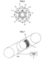
- Fig. 6 which shows an example of the arrangement of the magnetic detection means 4a to 4h, the magnetic detection means 4a, 4c, 4e and 4g are located so that they deliver positive outputs with respect to magnetic fluxes outward from the center of the wire-rope, and the remaining magnetic detection means are arranged so that they deliver negative outputs with respect to magnetic fluxes outward from the center of the wire-rope.
- the value of difference can be obtained from the sum of outputs from the respective magnetic means.
- Fig. 7 which shows the case that coils are used, the directions of winding of the coils are alternately reversed in order to set the directions of sensitiveness to be alternate, all coils being connected in series so as to obtain a difference value.
- the magnetic detection means may be those which can detect a circumferential magnetic flux distribution, and accordingly, for example, the sum of the outputs from a plurality of divided magnetic detection means may be used, being substituted for the outputs of the magnetic detection means.
- the intervals of the respective magnetic means should be set to be small in order to a peak of a leakage flux caused by damage can be surely measured.
- the first magnetic detection means, the second magnetic detection means 4a to 4h and the third magnetic detection means 4i to 4p are arranged being shifted from one another in the longitudinal direction of the wire-rope.
- This configuration can facilitate the mounting of the magnetic detection means onto the wire-rope since their respective wirings are not overlapped with one another.
- time compensators 14a to 14c are provided so that output values from the respective magnetic detection means exhibit measured data in the one and the same section of the wire-rope. That is, during measurements, when the wire-rope 1 is travelled, the outputs of the magnetic detection means are delayed by 2L/v where v is traveling speed (m/sec), and L is a distance (m) by which the magnetic detection means 3 and the magnetic detection mean 4a to 4h and 4i to 4p are shifted from one another, in the case that the wire-rope passes at first through the magnetic detection means 3, then passes by the magnetic detection means 4a to 4h, and finally passes by the magnetic detection means 4i to 4p, that is, the processing of the outputs of the magnetic detection means 4a to 4h are made by delaying their outputs by 2L/V.
- a storage 15 is stored therein with values of correction times with respect to speeds of the wire-ropes, and accordingly, the time compensators 14a to 14c carry out the time correction, being based upon these values, and the results thereof are delivered from the total meter 5 and the difference meter 6.
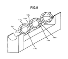
- Fig. 9 shows a third embodiment in which a wire-rope on use is fixed at its ends, the flaw detector is split into a plurality of sensor units so that the flaw detector can be easily inserted onto the wire-rope.
- the first magnetic detection means two halves, that is, magnetic detection means 17a and 17b are connected so that the sum of outputs therefrom is delivered.
- the magnetic detection means 4a to 4h and the magnetic detection means 4i to 4p some of them would be possibly located at the split plane 16, and accordingly, each of the some crossing the split plane 16 is split into two parts whose sensitivities are adjusted so that the sum of outputs from them is equal to the output of the magnetic detection means which has not yet been split.
- two magnetic detection means 18a and 18b are arranged interposing therebetween the split plane 16, instead of the magnetic detection means 4c, and the sensitivities thereof are set to a value which is one half of that of the magnetic detection means 4c.
- two magnetic detection means 18a and 18d are arranged, instead of the magnetic detection means 4g.
- coils are used as the magnetic detection means, their numbers of turns may be set to be equal to one another while their sectional areas are set to one-half of that of the original magnetic detection means. It is noted that the adjustment for the sensitivity may be always made not only by the adjustment to the sectional area but also by the adjustment to the number of turns, the adjustment to an electric gain made by an amplifier, or by the combination thereof.
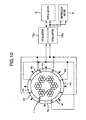
- Fig. 10 shows a fourth embodiment in which the second and third magnetic detection means are laid along the entire periphery of the wire-rope while the first magnetic detection means is omitted.
- the sum of outputs from the magnetic detection means 4a, 4c, 4e and 4g is measured by a sing total member 19a while the sum of outputs from the magnetic detection means 4b, 4d, 4f and 4h is measured by a single total meter 19b. Further, the sum of outputs from the total meter 19a and the total meter 19b corresponds to the total value measured by the first magnetic detection means, and the difference between the outputs from the total meter 19a and the total meter 19b corresponds to the difference value measured by the second magnetic detection means.
- the first magnetic detection means can be omitted, and further, the burden of the calibration for the respective magnetic detection means can be reduced.
Landscapes
- Chemical & Material Sciences (AREA)
- Chemical Kinetics & Catalysis (AREA)
- Electrochemistry (AREA)
- Physics & Mathematics (AREA)
- Health & Medical Sciences (AREA)
- Life Sciences & Earth Sciences (AREA)
- Analytical Chemistry (AREA)
- Biochemistry (AREA)
- General Health & Medical Sciences (AREA)
- General Physics & Mathematics (AREA)
- Immunology (AREA)
- Pathology (AREA)
- Investigating Or Analyzing Materials By The Use Of Magnetic Means (AREA)
- Measurement Of Length, Angles, Or The Like Using Electric Or Magnetic Means (AREA)
Applications Claiming Priority (1)
| Application Number | Priority Date | Filing Date | Title |
|---|---|---|---|
| JP2007136110A JP4894620B2 (ja) | 2007-05-23 | 2007-05-23 | ワイヤーロープの探傷装置 |
Publications (3)
| Publication Number | Publication Date |
|---|---|
| EP1995589A2 true EP1995589A2 (de) | 2008-11-26 |
| EP1995589A3 EP1995589A3 (de) | 2010-05-26 |
| EP1995589B1 EP1995589B1 (de) | 2020-01-01 |
Family
ID=39682664
Family Applications (1)
| Application Number | Title | Priority Date | Filing Date |
|---|---|---|---|
| EP08009385.9A Active EP1995589B1 (de) | 2007-05-23 | 2008-05-21 | Rissdetektor für ein Drahtseil |
Country Status (3)
| Country | Link |
|---|---|
| EP (1) | EP1995589B1 (de) |
| JP (1) | JP4894620B2 (de) |
| CN (1) | CN101311713B (de) |
Cited By (9)
| Publication number | Priority date | Publication date | Assignee | Title |
|---|---|---|---|---|
| WO2011109869A1 (en) * | 2010-03-10 | 2011-09-15 | Jrb Engineering Pty Ltd | Method and apparatus for magnetic crack depth prediction |
| EP3086115A1 (de) * | 2015-04-13 | 2016-10-26 | Fatzer AG Drahtseilfabrik | Prüfungs- und überwachungssystem für eine seilbahn, insbesondere für einen urbanen transport von personen und gütern, sowie ein verfahren zum betrieb derselben |
| US9822375B2 (en) | 2009-12-23 | 2017-11-21 | University College Dublin, National University Of Ireland | Method of transforming cells |
| CN112649495A (zh) * | 2020-12-22 | 2021-04-13 | 洛阳威尔若普检测技术有限公司 | 钢丝绳探伤装置及方法 |
| CN114660257A (zh) * | 2022-03-11 | 2022-06-24 | 江阴兴澄特种钢铁有限公司 | 一种钢丝绳的探伤检测装置 |
| CN115290743A (zh) * | 2022-09-26 | 2022-11-04 | 江苏惠博机电科技股份有限公司 | 一种电机减震底座用螺旋体检测装置 |
| CN115808512A (zh) * | 2022-11-30 | 2023-03-17 | 华中科技大学 | 一种用于钢丝绳检测的柔性跟踪装置及其应用 |
| CN118258880A (zh) * | 2024-03-14 | 2024-06-28 | 宁波日通电梯工程有限公司 | 一种电梯钢丝绳探伤设备 |
| CN118668607A (zh) * | 2024-08-22 | 2024-09-20 | 中交二公局第一工程有限公司 | 一种悬索桥缆索系统拆除支架及其使用方法 |
Families Citing this family (18)
| Publication number | Priority date | Publication date | Assignee | Title |
|---|---|---|---|---|
| WO2013023818A1 (en) * | 2011-08-18 | 2013-02-21 | Nv Bekaert Sa | Magnetic flux leakage error detection in cords |
| CN102507726A (zh) * | 2011-10-08 | 2012-06-20 | 南京润奇检测仪器有限公司 | 一种新型漏磁传感器探头 |
| CN105883515A (zh) * | 2014-12-24 | 2016-08-24 | 天津利洋润杰科技有限公司 | 一种电梯钢绞线探伤装置 |
| DE112015007083B4 (de) * | 2015-11-02 | 2022-06-23 | Mitsubishi Electric Corporation | Vorrichtung zum detektieren von drahtseildefekten |
| CN105668362A (zh) * | 2016-02-24 | 2016-06-15 | 李华敏 | 电梯自动减速和制动系统 |
| CN105675713B (zh) * | 2016-04-06 | 2018-08-07 | 山西慧达澳星科技有限公司 | 一种电梯曳引钢带无损检测装置及方法 |
| CN105784837A (zh) * | 2016-04-26 | 2016-07-20 | 常州机电职业技术学院 | 一种多股金属绳损伤检测方法及系统 |
| CN106093184B (zh) * | 2016-07-08 | 2019-11-26 | 中铁大桥科学研究院有限公司 | 桥梁拉索电磁探伤装置及其应用 |
| TWI681184B (zh) * | 2017-12-21 | 2020-01-01 | 國立虎尾科技大學 | 應用於pcb多層板之非接觸式上下層銅厚的量測方法 |
| JP6863518B2 (ja) * | 2018-03-08 | 2021-04-21 | 株式会社島津製作所 | 磁性体検査装置 |
| CN108709928A (zh) * | 2018-08-30 | 2018-10-26 | 洛阳泰斯特探伤技术有限公司 | 一种单绳物联探头装置 |
| CN110006338B (zh) * | 2019-04-28 | 2020-11-06 | 哈尔滨工业大学(深圳) | 一种钢丝绳损伤面积检测方法 |
| CN113811763A (zh) * | 2019-06-14 | 2021-12-17 | 株式会社岛津制作所 | 磁性体的劣化预测装置和磁性体的劣化预测方法 |
| CN110980471B (zh) * | 2019-12-31 | 2020-12-01 | 界首市迅立达电梯有限公司 | 一种基于物联网的电梯曳引机钢丝绳状态预警系统 |
| CN112415083A (zh) * | 2020-12-03 | 2021-02-26 | 河北工业大学 | 一种狭小工况下的钢丝绳缺陷快速检测装置 |
| JP7637574B2 (ja) * | 2021-06-15 | 2025-02-28 | 株式会社日立ビルシステム | ワイヤーロープ探傷装置 |
| DE102022213735A1 (de) | 2022-12-15 | 2024-06-20 | Institut Dr. Foerster Gmbh & Co. Kg | Prüfverfahren und Prüfvorrichtung zur Streuflussprüfung von Drahtseilen |
| JP7747138B1 (ja) * | 2024-08-05 | 2025-10-01 | フジテック株式会社 | ロープテスタ |
Citations (2)
| Publication number | Priority date | Publication date | Assignee | Title |
|---|---|---|---|---|
| JPH07198684A (ja) | 1993-12-28 | 1995-08-01 | Tokyo Seiko Co Ltd | ワイヤロープの損傷検出器 |
| JP2002005896A (ja) | 2000-06-26 | 2002-01-09 | Toshiba Elevator Co Ltd | ワイヤロープ探傷装置 |
Family Cites Families (13)
| Publication number | Priority date | Publication date | Assignee | Title |
|---|---|---|---|---|
| CN85100207B (zh) * | 1985-04-01 | 1987-07-01 | 煤炭工业部煤炭科学研究院抚顺研究所 | 钢丝绳断丝定量探伤仪 |
| JPH04240561A (ja) * | 1991-01-25 | 1992-08-27 | Nkk Corp | ワイヤロープの磁気探傷方法及びその装置 |
| CN1040797C (zh) * | 1992-12-30 | 1998-11-18 | 华中理工大学 | 定量检测细长导磁构件缺陷的装置和方法 |
| CN2270973Y (zh) * | 1996-02-01 | 1997-12-17 | 储东生 | 永久磁铁探伤仪 |
| JPH10177010A (ja) * | 1996-12-18 | 1998-06-30 | Hitachi Ltd | 損傷検出方法 |
| JP3285829B2 (ja) * | 1998-09-03 | 2002-05-27 | 三菱重工業株式会社 | 架空電線の探傷装置および探傷方法 |
| US6492808B1 (en) * | 2000-06-29 | 2002-12-10 | Intron Plus, Ltd. | Magnetic non-destructive method and apparatus for measurement of cross sectional area and detection of local flaws in elongated ferrous objects in response to longitudinally spaced sensors in an inter-pole area |
| JP2002116187A (ja) * | 2000-10-06 | 2002-04-19 | Mitsui Miike Mach Co Ltd | 鋼索用磁気探傷装置および感磁性素子解析方法 |
| JP2002257789A (ja) * | 2001-02-28 | 2002-09-11 | Nkk Corp | 漏洩磁束検出装置 |
| JP2004279248A (ja) * | 2003-03-17 | 2004-10-07 | Tokyo Gas Co Ltd | データ解析方法、データ解析装置、プログラム、及び記録媒体 |
| JP4179141B2 (ja) * | 2003-11-19 | 2008-11-12 | 株式会社Ihi | ワイヤロープの磁気探傷装置 |
| JP4286693B2 (ja) * | 2004-03-25 | 2009-07-01 | 内橋エステック株式会社 | 電線の導体欠陥検知方法 |
| JP4295774B2 (ja) * | 2006-07-20 | 2009-07-15 | 株式会社日立ビルシステム | ワイヤーロープの探傷装置 |
-
2007
- 2007-05-23 JP JP2007136110A patent/JP4894620B2/ja active Active
-
2008
- 2008-05-20 CN CN2008101005219A patent/CN101311713B/zh active Active
- 2008-05-21 EP EP08009385.9A patent/EP1995589B1/de active Active
Patent Citations (2)
| Publication number | Priority date | Publication date | Assignee | Title |
|---|---|---|---|---|
| JPH07198684A (ja) | 1993-12-28 | 1995-08-01 | Tokyo Seiko Co Ltd | ワイヤロープの損傷検出器 |
| JP2002005896A (ja) | 2000-06-26 | 2002-01-09 | Toshiba Elevator Co Ltd | ワイヤロープ探傷装置 |
Cited By (14)
| Publication number | Priority date | Publication date | Assignee | Title |
|---|---|---|---|---|
| US9822375B2 (en) | 2009-12-23 | 2017-11-21 | University College Dublin, National University Of Ireland | Method of transforming cells |
| WO2011109869A1 (en) * | 2010-03-10 | 2011-09-15 | Jrb Engineering Pty Ltd | Method and apparatus for magnetic crack depth prediction |
| AU2011226745B2 (en) * | 2010-03-10 | 2016-01-14 | Robel Holding Gmbh | Method and apparatus for magnetic crack depth prediction |
| US9599592B2 (en) | 2010-03-10 | 2017-03-21 | Ian Stewart Blair | Method and apparatus for magnetic crack depth prediction |
| EP3086115A1 (de) * | 2015-04-13 | 2016-10-26 | Fatzer AG Drahtseilfabrik | Prüfungs- und überwachungssystem für eine seilbahn, insbesondere für einen urbanen transport von personen und gütern, sowie ein verfahren zum betrieb derselben |
| US10370007B2 (en) | 2015-04-13 | 2019-08-06 | Fatzer Ag Drahtseilfabrik | Inspection and monitoring system for a cable railway and a method of operating the same |
| CN112649495A (zh) * | 2020-12-22 | 2021-04-13 | 洛阳威尔若普检测技术有限公司 | 钢丝绳探伤装置及方法 |
| CN114660257A (zh) * | 2022-03-11 | 2022-06-24 | 江阴兴澄特种钢铁有限公司 | 一种钢丝绳的探伤检测装置 |
| CN114660257B (zh) * | 2022-03-11 | 2024-05-17 | 江阴兴澄特种钢铁有限公司 | 一种钢丝绳的探伤检测装置 |
| CN115290743A (zh) * | 2022-09-26 | 2022-11-04 | 江苏惠博机电科技股份有限公司 | 一种电机减震底座用螺旋体检测装置 |
| CN115290743B (zh) * | 2022-09-26 | 2022-12-16 | 江苏惠博机电科技股份有限公司 | 一种电机减震底座用螺旋体检测装置 |
| CN115808512A (zh) * | 2022-11-30 | 2023-03-17 | 华中科技大学 | 一种用于钢丝绳检测的柔性跟踪装置及其应用 |
| CN118258880A (zh) * | 2024-03-14 | 2024-06-28 | 宁波日通电梯工程有限公司 | 一种电梯钢丝绳探伤设备 |
| CN118668607A (zh) * | 2024-08-22 | 2024-09-20 | 中交二公局第一工程有限公司 | 一种悬索桥缆索系统拆除支架及其使用方法 |
Also Published As
| Publication number | Publication date |
|---|---|
| CN101311713A (zh) | 2008-11-26 |
| EP1995589A3 (de) | 2010-05-26 |
| CN101311713B (zh) | 2011-06-08 |
| JP2008292213A (ja) | 2008-12-04 |
| EP1995589B1 (de) | 2020-01-01 |
| HK1126002A1 (en) | 2009-08-21 |
| JP4894620B2 (ja) | 2012-03-14 |
Similar Documents
| Publication | Publication Date | Title |
|---|---|---|
| EP1995589B1 (de) | Rissdetektor für ein Drahtseil | |
| EP2788781B1 (de) | Magnetische untersuchungsvorrichtung und verfahren dafür | |
| ES2635266T3 (es) | Procedimiento y equipo para la detección de degradación de una soga de ascensor usando energía magnética | |
| EP3748351B1 (de) | Vorrichtung zum prüfen von drahtseilen, system zum prüfen von drahtseilen und verfahren zum prüfen von drahtseilen | |
| EP3475209B1 (de) | Vorrichtung und verfahren zur messung von eigenschaften eines seils | |
| JP4825525B2 (ja) | ワイヤロープの探傷装置 | |
| DK3069131T3 (en) | DEVICE AND DEVICE FOR MONITORING A CONDITION OF A ELEVATED IRON OBJECTIVE WITH A LENGTH SHEET | |
| Schlanbusch et al. | Condition monitoring technologies for steel wire ropes–a review | |
| JP2005156419A (ja) | ワイヤロープの磁気探傷装置 | |
| JP2010008213A (ja) | ワイヤロープ損傷検出器 | |
| CN117665096A (zh) | 一种钢丝绳的磁探伤方法及装置 | |
| JP5210532B2 (ja) | 簡易ロープ異常検知装置 | |
| JP5195437B2 (ja) | シーブおよびつり上げ装置 | |
| JP7771829B2 (ja) | ワイヤロープ検査システム | |
| HK1126002B (zh) | 钢丝绳的探伤设备 | |
| CN209246989U (zh) | 一种检测桥梁拉索外形截面形状的检测仪 | |
| JP7757243B2 (ja) | ワイヤロープ探傷装置およびワイヤロープ診断方法 | |
| CN109668538A (zh) | 一种检测桥梁拉索外形截面形状的检测仪 | |
| JP7037854B2 (ja) | ロープ径超音波測定治具 | |
| Singh et al. | Steel wire rope condition monitoring by non-destructive investigation and evaluation while on installation/service | |
| Stawowiak et al. | An assessment of rope durability in mining shaft hoists | |
| KR20120096677A (ko) | 와이어로프 국부결함 탐지장치 | |
| FI89107B (fi) | Foerfarande och anordning foer kontrollering av en lyftlinas skick | |
| Basak et al. | Performance evaluation of Track ropes using two non Destructive Testing Instruments | |
| Basak et al. | Nondestructive study of aerial track and haulage ropes in a zigback passenger cable car system |
Legal Events
| Date | Code | Title | Description |
|---|---|---|---|
| PUAI | Public reference made under article 153(3) epc to a published international application that has entered the european phase |
Free format text: ORIGINAL CODE: 0009012 |
|
| 17P | Request for examination filed |
Effective date: 20080521 |
|
| AK | Designated contracting states |
Kind code of ref document: A2 Designated state(s): AT BE BG CH CY CZ DE DK EE ES FI FR GB GR HR HU IE IS IT LI LT LU LV MC MT NL NO PL PT RO SE SI SK TR |
|
| AX | Request for extension of the european patent |
Extension state: AL BA MK RS |
|
| PUAL | Search report despatched |
Free format text: ORIGINAL CODE: 0009013 |
|
| AK | Designated contracting states |
Kind code of ref document: A3 Designated state(s): AT BE BG CH CY CZ DE DK EE ES FI FR GB GR HR HU IE IS IT LI LT LU LV MC MT NL NO PL PT RO SE SI SK TR |
|
| AX | Request for extension of the european patent |
Extension state: AL BA MK RS |
|
| AKX | Designation fees paid |
Designated state(s): DE FR |
|
| 17Q | First examination report despatched |
Effective date: 20151217 |
|
| STAA | Information on the status of an ep patent application or granted ep patent |
Free format text: STATUS: EXAMINATION IS IN PROGRESS |
|
| GRAP | Despatch of communication of intention to grant a patent |
Free format text: ORIGINAL CODE: EPIDOSNIGR1 |
|
| STAA | Information on the status of an ep patent application or granted ep patent |
Free format text: STATUS: GRANT OF PATENT IS INTENDED |
|
| INTG | Intention to grant announced |
Effective date: 20190819 |
|
| GRAS | Grant fee paid |
Free format text: ORIGINAL CODE: EPIDOSNIGR3 |
|
| GRAA | (expected) grant |
Free format text: ORIGINAL CODE: 0009210 |
|
| STAA | Information on the status of an ep patent application or granted ep patent |
Free format text: STATUS: THE PATENT HAS BEEN GRANTED |
|
| AK | Designated contracting states |
Kind code of ref document: B1 Designated state(s): DE FR |
|
| RIN1 | Information on inventor provided before grant (corrected) |
Inventor name: ARIGA, MASAKI Inventor name: ASAI, DAISUKE |
|
| REG | Reference to a national code |
Ref country code: DE Ref legal event code: R096 Ref document number: 602008061917 Country of ref document: DE |
|
| REG | Reference to a national code |
Ref country code: DE Ref legal event code: R097 Ref document number: 602008061917 Country of ref document: DE |
|
| PLBE | No opposition filed within time limit |
Free format text: ORIGINAL CODE: 0009261 |
|
| STAA | Information on the status of an ep patent application or granted ep patent |
Free format text: STATUS: NO OPPOSITION FILED WITHIN TIME LIMIT |
|
| 26N | No opposition filed |
Effective date: 20201002 |
|
| REG | Reference to a national code |
Ref country code: FR Ref legal event code: PLFP Year of fee payment: 16 |
|
| PGFP | Annual fee paid to national office [announced via postgrant information from national office to epo] |
Ref country code: DE Payment date: 20250402 Year of fee payment: 18 |
|
| PGFP | Annual fee paid to national office [announced via postgrant information from national office to epo] |
Ref country code: FR Payment date: 20250401 Year of fee payment: 18 |