EP1995590A1 - Procédé et appareil de mesure numérique d'un signal par courants de Foucault - Google Patents
Procédé et appareil de mesure numérique d'un signal par courants de Foucault Download PDFInfo
- Publication number
- EP1995590A1 EP1995590A1 EP08156681A EP08156681A EP1995590A1 EP 1995590 A1 EP1995590 A1 EP 1995590A1 EP 08156681 A EP08156681 A EP 08156681A EP 08156681 A EP08156681 A EP 08156681A EP 1995590 A1 EP1995590 A1 EP 1995590A1
- Authority
- EP
- European Patent Office
- Prior art keywords
- digital
- return signal
- signal
- analog
- test object
- Prior art date
- Legal status (The legal status is an assumption and is not a legal conclusion. Google has not performed a legal analysis and makes no representation as to the accuracy of the status listed.)
- Withdrawn
Links
- 238000000034 method Methods 0.000 title claims abstract description 11
- 238000005259 measurement Methods 0.000 title claims description 11
- 238000012360 testing method Methods 0.000 claims abstract description 60
- 230000010363 phase shift Effects 0.000 claims abstract description 37
- 239000000523 sample Substances 0.000 claims abstract description 26
- 230000005672 electromagnetic field Effects 0.000 claims abstract description 19
- 239000000463 material Substances 0.000 claims abstract description 11
- 230000000007 visual effect Effects 0.000 claims description 4
- 238000001914 filtration Methods 0.000 claims 1
- 230000007547 defect Effects 0.000 description 12
- 230000004044 response Effects 0.000 description 5
- 230000008859 change Effects 0.000 description 3
- 238000010586 diagram Methods 0.000 description 3
- 238000012545 processing Methods 0.000 description 3
- 238000004364 calculation method Methods 0.000 description 2
- 238000007689 inspection Methods 0.000 description 2
- 238000012544 monitoring process Methods 0.000 description 2
- 230000000149 penetrating effect Effects 0.000 description 2
- 238000004458 analytical method Methods 0.000 description 1
- 238000006243 chemical reaction Methods 0.000 description 1
- 230000008030 elimination Effects 0.000 description 1
- 238000003379 elimination reaction Methods 0.000 description 1
- 238000011156 evaluation Methods 0.000 description 1
- 230000006870 function Effects 0.000 description 1
- 238000004519 manufacturing process Methods 0.000 description 1
- 230000035699 permeability Effects 0.000 description 1
- 230000002688 persistence Effects 0.000 description 1
- 238000003672 processing method Methods 0.000 description 1
Images


Classifications
-
- G—PHYSICS
- G01—MEASURING; TESTING
- G01N—INVESTIGATING OR ANALYSING MATERIALS BY DETERMINING THEIR CHEMICAL OR PHYSICAL PROPERTIES
- G01N27/00—Investigating or analysing materials by the use of electric, electrochemical, or magnetic means
- G01N27/72—Investigating or analysing materials by the use of electric, electrochemical, or magnetic means by investigating magnetic variables
- G01N27/82—Investigating or analysing materials by the use of electric, electrochemical, or magnetic means by investigating magnetic variables for investigating the presence of flaws
- G01N27/90—Investigating or analysing materials by the use of electric, electrochemical, or magnetic means by investigating magnetic variables for investigating the presence of flaws using eddy currents
- G01N27/9046—Investigating or analysing materials by the use of electric, electrochemical, or magnetic means by investigating magnetic variables for investigating the presence of flaws using eddy currents by analysing electrical signals
Definitions
- This invention generally relates to measurement of eddy current signals using digital signal processing techniques.
- an oscillator or other signal generator produces an alternating current (AC) drive signal (e.g., a sine wave) that drives a coil of an eddy current probe placed in close proximity to an electrically conductive test object.
- the drive signal in the probe coil produces an electromagnetic field, which penetrates into the electrically conductive test object and induces eddy currents in the test object, which in turn generate their own electromagnetic field.
- the frequency of the drive signal as well as material properties of the test object determines the depth that a particular electromagnetic field penetrates the test object, with lower frequency signals penetrating deeper than higher frequency signals. For most inspection applications, eddy current probe frequencies in the range 1kHz to 3MHz are used.
- the electromagnetic field generated by the eddy currents generates a return signal in the eddy current probe.
- Comparison of the drive signal to the return signal can provide information regarding the material characteristics of the test object, including the existence of flaws or other defects at a particular depth. Placing the eddy current probe over a section of the test object that is known to have no flaws or defects results in the creation of a return signal that can be used to establish a reference or null signal. Determining the differences (e.g., phase shift) between the drive signal and this reference or null signal establishes reference data against which subsequent measurements of unknown sections of the test object may be made.
- a critical step in eddy current testing is determining the differences (e.g., phase shift) between the drive signal and return signal.
- Analog methods for determining the differences between the drive signal and return signal in eddy current testing are well known.
- one or more oscillators are used to generate a sine signal and a cosine signal having the same frequency and amplitude as the drive signal.
- each of the sine and cosine signals is mixed or multiplied with the return signal, which has been amplified prior to the mixing or multiplication.
- Each of the resulting signals from the multipliers contain the sum and difference products of the two signals that were multiplied and contain the amplitude and phase information of the difference signal based on the test object return signal. Those resulting signals are then low pass filtered to remove all but the difference frequencies and any low harmonic products.
- the signals After summing and amplifying the resulting signals, the signals represent the quadrature signals of the difference between the drive signal and the return signal, from which the phase and amplitude of that difference signal can be derived.
- the quadrature signals are multiplexed, passed through an analog to digital converter, and then received by a computer or other processor to analyze the signals and determine the presence of a flaw or other defect.
- Digital circuitry has several inherent advantages over analog circuitry, including a reduced number of components, which may result in reduced manufacturing costs, and the elimination or minimization of the potential impact caused by variations in component tolerances. Given these advantages, with advent of the digital signal processing, others have replaced the analog circuitry and operations described above with digital circuitry. While this change may improve the performance and cost of the application, the digital circuitry still must perform the calculations of multiplying the return signal with the sine and cosine signals to produce quadrature outputs, which are then analyzed to determine the phase and amplitude of the difference signal. It would be advantageous to use digital signal processing techniques to perform eddy current testing without the need to multiply the return signal with the sine and cosine signals.
- a method and apparatus for conducting eddy current testing of a test object comprising the steps of generating a digital drive signal, converting the digital drive signal to an analog drive signal to drive a coil in a probe; placing the probe in proximity to a test object; receiving an electromagnetic field generated by the test object, which generates an analog return signal; converting the analog return signal to a digital return signal; measuring the amplitude of the digital return signal; measuring the phase shift of the digital return signal compared to the digital drive signal; determining the phase shift angle of the digital return signal based on the phase shift; determining the quadrature components of the digital return signal based on the digital return signal amplitude and the phase shift angle; and analyzing the quadrature components of the digital return signal to determine a material characteristic of the test object.
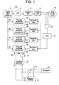
- FIG. 1 shows a block diagram of a digital circuit used to perform eddy current testing using digital signal processing methods.
- a digital signal generator or waveform synthesizer 10 can generate a digital drive signal 100.
- the digital drive signal 100 can be a single frequency signal or multiple frequency signal depending on the whether inspection of one or more depths or other parameters in a test object is required.
- the digital drive signal 100 has a measurable amplitude (D) 102 and selected time reference (T0) 104, which can be used for later comparison with the digital return signal 200.
- the amplitude can be measured as a peak value or as a peak to peak value.
- the digital drive signal 100 is then passed through a digital to analog converter (DAC) 12, creating the analog drive signal that is then passed through a low pass filter 14.
- DAC digital to analog converter
- the filtered analog drive signal is then received by a probe driver 16, which drives a coil (not shown) in the eddy current probe 18.
- the eddy current probe 18 generates an electromagnetic field, which, when placed in close proximity to an electrically conductive test object (not shown), penetrates into the test object and induces eddy currents in the test object, which in turn generate their own electromagnetic field.
- the electromagnetic field generated by the eddy currents generates an analog return signal in the eddy current probe 18.
- the analog return signal is received by the eddy current probe 18 and then amplified by an amplifier 20, passed through an analog to digital converter (ADC) 22, and then passed through one or more band pass filters 24, creating the digital return signal 200.
- ADC analog to digital converter
- band pass filters 24 can be used to isolate the data from different depths of the test object or to compensate for lift off.
- Digital devices can be used to provide the function of the band pass filters 24 (i.e., isolating a frequency or narrow band of frequencies of interest).
- the digital return signal 200 for a particular frequency or band of frequencies has a measurable amplitude (R) 202 and measurable time or phase shift (Ts) 204 when compared to the time reference (To) 104 of the digital drive signal 100 for that frequency or band of frequencies.
- the amplitude can be measured as a peak value or as a peak to peak value.
- Both the digital drive signal 100 and digital return signal 200 can have the same period (T) 106.
- FIG. 3 shows a vector representation of the amplitude (R) 202 and phase shift angle ( ⁇ ) 206 of the digital return signal 200.
- the time and amplitude measurement device 26 determines the amplitude (R) 202 and phase shift angle ( ⁇ ) 206 of the digital return signal 200 and can be implemented using any one of several digital devices, including a FPGA, a DSP or other digital devices.
- the phase shift angle ( ⁇ ) 206 of the digital return signal 200 can be determined by calculating the ratio of the time or phase shift (Ts) 204 of the digital return signal 200 over the period (T) 106 and then multiplying that ratio by 360°.
- the amplitude (R) 202 of the digital return signal 200 can be measured directly by determining the peak or peak to peak value of the signal.
- the amplitude (R) 202 and phase shift angle ( ⁇ ) 206 of the digital return signal 200 can be processed in polar form directly or can be converted to X,Y coordinates as is the more conventional eddy current method. Knowledge of the amplitude and phase angle of a signal enables calculation of the quadrature (sine and cosine) components (X and Y) of that signal.
- a coordinate converter 28 can convert the amplitude (R) 202 and phase shift angle ( ⁇ ) 206 of the digital return signal 200 to quadrature form by multiplying the amplitude (R) 202 by the cosine and the sine of the phase shift angle ( ⁇ ) 206 respectively.
- the digital signal generator or waveform synthesizer 10 of FIG. 1 can provide a digital drive signal 100 at multiple frequencies.
- the particular depth of interest can be chosen by analyzing digital return signal 200 and the digital drive signal 100 for the frequency corresponding to that depth.
- Multiple-frequency analysis can be performed by providing multiple band pass filters 34, 44, 54, and time and amplitude measurement blocks 36, 46, 56 to determine the amplitude (R) 202 and phase shift angle ( ⁇ ) 206 for the digital return signals 200 for the relevant frequencies.
- the measured amplitude (R) 202 and phase shift angle ( ⁇ ) 206 of the digital return signals 200 are passed to a computer or other processor 40 where they are analyzed to determine the presence of a flaw or defect in the test object or other change in material characteristics.
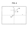
- the results of an eddy current measurement are shown in the impedance plane and on a display 403 viewed by a user as shown in FIG. 4 .
- This display 403 may be a computer screen or similar device.
- a visual indicator or spot on the display 403 moves based on the measured amplitude (R) 202 and phase shift angle ( ⁇ ) 206 of the digital return signal 200. Since the display 403 has persistence, the recent movements of the spot can be observed.
- defects in the test object can be distinguished from eddy current probe 18 lift-off by the fact that lift off causes the spot to move orthogonally to movement caused by defects. This difference can be optimized by probe frequency selection.
- the response from the probe 18 lifting off the test object is shown as 400.
- the response to a defect is shown as 401.
- null signal an analog return signal or digital return signal at this location, which is referred to as a null signal.
- This null signal or its measured values e.g., amplitude and phase shift angle or quadrature components
- This subtraction can be accomplished in several ways, including injecting a signal that is equal and opposite to the null signal to the subsequently generated analog return signals or digital return signals for unknown locations.
- Subtracting or injecting the null signal can be done at any point in the signal chain.
- the quadrature components of the amplitude and phase shift angle of the null signal are stored in reference memory 30. During subsequent testing, these values are automatically subtracted from the quadrature components of the amplitude (R) 202 and phase shift angle ( ⁇ ) 206 of the digital return signals 200 using subtracters or adders 31, 32.
- a signal that is equal and opposite to the null signal can be injected to the analog return signal prior to conversion by the ADC 22.
- a simple threshold 402 can be set, representing the maximum allowable response before a defect is reported.
- Automatic evaluation of the amplitude (R) 202 and phase shift angle ( ⁇ ) 206 of the digital return signal 200 can be performed in this way. If the visual indicator or spot exceeds a threshold 402 in the vertical direction, an alarm can be set or other actions taken by the computer or other monitoring circuits.
- a constant can be added or subtracted to the phase shift angle ( ⁇ ) 206 of the digital return signal (200). This can be accomplished using a phase rotation device 27 to add or subtract a constant to the phase shift angle ( ⁇ ) 206 as shown in FIG. 1 .
Landscapes
- Chemical & Material Sciences (AREA)
- Chemical Kinetics & Catalysis (AREA)
- Electrochemistry (AREA)
- Physics & Mathematics (AREA)
- Health & Medical Sciences (AREA)
- Life Sciences & Earth Sciences (AREA)
- Analytical Chemistry (AREA)
- Biochemistry (AREA)
- General Health & Medical Sciences (AREA)
- General Physics & Mathematics (AREA)
- Immunology (AREA)
- Pathology (AREA)
- Investigating Or Analyzing Materials By The Use Of Magnetic Means (AREA)
Applications Claiming Priority (1)
| Application Number | Priority Date | Filing Date | Title |
|---|---|---|---|
| US11/752,698 US20080290866A1 (en) | 2007-05-23 | 2007-05-23 | Method and apparatus for digital measurement of an eddy current signal |
Publications (1)
| Publication Number | Publication Date |
|---|---|
| EP1995590A1 true EP1995590A1 (fr) | 2008-11-26 |
Family
ID=39709377
Family Applications (1)
| Application Number | Title | Priority Date | Filing Date |
|---|---|---|---|
| EP08156681A Withdrawn EP1995590A1 (fr) | 2007-05-23 | 2008-05-21 | Procédé et appareil de mesure numérique d'un signal par courants de Foucault |
Country Status (5)
| Country | Link |
|---|---|
| US (1) | US20080290866A1 (fr) |
| EP (1) | EP1995590A1 (fr) |
| JP (1) | JP2008292485A (fr) |
| CN (1) | CN101311715A (fr) |
| CA (1) | CA2630899A1 (fr) |
Cited By (2)
| Publication number | Priority date | Publication date | Assignee | Title |
|---|---|---|---|---|
| EP2618140A2 (fr) | 2012-01-20 | 2013-07-24 | Prüftechnik Dieter Busch AG | Configuration de test et procédé de test pour détection non destructive de défaut dans un dispositif à l'essai au moyen d'un courant de Foucault |
| US8841902B2 (en) | 2012-01-20 | 2014-09-23 | Prüftechnik Dieter Busch AG | Testing device and testing method for non destructive detection of a defect in a test piece by means of an eddy current |
Families Citing this family (17)
| Publication number | Priority date | Publication date | Assignee | Title |
|---|---|---|---|---|
| US20080238417A1 (en) * | 2007-03-29 | 2008-10-02 | Canon Denshi Kabushiki Kaisha | Magnetic substance detection sensor and magnetic substance detecting apparatus |
| US20120126825A1 (en) * | 2010-11-22 | 2012-05-24 | Boris Leonid Sheikman | Sensor assembly and methods of measuring the proximity of a component to an emitter |
| CN102087245B (zh) * | 2010-12-04 | 2012-09-19 | 南昌航空大学 | 基于非晶合金的电磁检测传感器 |
| GB2481482B (en) * | 2011-04-27 | 2012-06-20 | Univ Manchester | Improvements in sensors |
| US20120276662A1 (en) * | 2011-04-27 | 2012-11-01 | Iravani Hassan G | Eddy current monitoring of metal features |
| JP2013145181A (ja) * | 2012-01-13 | 2013-07-25 | Aichi Machine Industry Co Ltd | 焼入れ処理評価装置および焼入れ処理評価方法 |
| US20130214768A1 (en) * | 2012-02-21 | 2013-08-22 | Varel International Ind., L.P. | Use of Eddy Currents to Analyze Polycrystalline Diamond |
| US9423370B2 (en) | 2012-02-21 | 2016-08-23 | Varel International Ind., L.P | Use of capacitance to analyze polycrystalline diamond |
| US9128031B2 (en) | 2012-02-21 | 2015-09-08 | Varel International Ind., L.P. | Method to improve the leaching process |
| US20130214769A1 (en) * | 2012-02-21 | 2013-08-22 | Varel International Ind., L.P. | Use of Capacitance And Eddy Currents to Analyze Polycrystalline Diamond |
| US9423436B2 (en) | 2012-02-21 | 2016-08-23 | Varel International Ind., L.P. | Method and apparatus to assess the thermal damage caused to a PCD cutter using capacitance spectroscopy |
| US9377428B2 (en) | 2012-02-21 | 2016-06-28 | Varel International Ind., L.P. | Non-destructive leaching depth measurement using capacitance spectroscopy |
| DE102012107534A1 (de) * | 2012-08-16 | 2014-02-20 | Endress + Hauser Flowtec Ag | Magnetisch-induktives Durchflussmessgerät |
| CN105965380B (zh) * | 2016-05-04 | 2017-09-19 | 中国电子科技集团公司第四十五研究所 | 用于晶片表面金属薄膜抛光过程的电涡流测量装置 |
| DE102016111963A1 (de) * | 2016-06-30 | 2018-01-04 | Fraunhofer-Gesellschaft zur Förderung der angewandten Forschung e.V. | Verfahren zum Auswerten eines digitalen Messsignals einer Wirbelstromprüfanordnung |
| KR20220060880A (ko) * | 2020-11-05 | 2022-05-12 | 주식회사 엘지에너지솔루션 | 전지 셀의 균열 검사를 위한 와전류 센서 및 이를 포함하는 전지 셀의 균열 검출 시스템 |
| CN115406960A (zh) * | 2022-08-30 | 2022-11-29 | 中广核检测技术有限公司 | 一种数字化多频涡流信号处理方法 |
Citations (2)
| Publication number | Priority date | Publication date | Assignee | Title |
|---|---|---|---|---|
| WO2001029500A2 (fr) * | 1999-10-22 | 2001-04-26 | Bently Nevada Corporation | Systeme de proximite numerique a courants de foucault: appareil et procede |
| US20040066189A1 (en) * | 2002-10-08 | 2004-04-08 | Estell Lopez | Dynamic gain control in a digital eddy current signal processor |
Family Cites Families (10)
| Publication number | Priority date | Publication date | Assignee | Title |
|---|---|---|---|---|
| US4207520A (en) * | 1978-04-06 | 1980-06-10 | The United States Of America As Represented By The Secretary Of The Air Force | Multiple frequency digital eddy current inspection system |
| US4424486A (en) * | 1980-10-14 | 1984-01-03 | Zetec, Inc. | Phase rotation circuit for an eddy current tester |
| US5055784A (en) * | 1987-12-07 | 1991-10-08 | American Research Corporation Of Virginia | Bridgeless system for directly measuring complex impedance of an eddy current probe |
| US5144565A (en) * | 1990-03-26 | 1992-09-01 | K. J. Law Engineers, Inc. | Measurement of metallurgical properties in ferromagnetic test parts |
| US5394084A (en) * | 1991-12-23 | 1995-02-28 | The Boeing Company | Method and apparatus for reducing errors in eddy-current conductivity measurements due to lift-off by interpolating between a plurality of reference conductivity measurements |
| US5514337A (en) * | 1994-01-11 | 1996-05-07 | American Research Corporation Of Virginia | Chemical sensor using eddy current or resonant electromagnetic circuit detection |
| US5541510A (en) * | 1995-04-06 | 1996-07-30 | Kaman Instrumentation Corporation | Multi-Parameter eddy current measuring system with parameter compensation technical field |
| US6636037B1 (en) * | 2000-03-31 | 2003-10-21 | Innovative Materials Testing Technologies | Super sensitive eddy-current electromagnetic probe system and method for inspecting anomalies in conducting plates |
| AU2002342054A1 (en) * | 2001-10-10 | 2003-04-22 | Ranger Security Detectors Inc. | System and method for scanning individuals for illicit objects |
| US7184901B1 (en) * | 2005-08-18 | 2007-02-27 | Chin Ming Chiang | Digitizing electrical measurement system |
-
2007
- 2007-05-23 US US11/752,698 patent/US20080290866A1/en not_active Abandoned
-
2008
- 2008-05-08 CA CA002630899A patent/CA2630899A1/fr not_active Abandoned
- 2008-05-21 JP JP2008132596A patent/JP2008292485A/ja not_active Withdrawn
- 2008-05-21 EP EP08156681A patent/EP1995590A1/fr not_active Withdrawn
- 2008-05-23 CN CNA2008101091106A patent/CN101311715A/zh active Pending
Patent Citations (2)
| Publication number | Priority date | Publication date | Assignee | Title |
|---|---|---|---|---|
| WO2001029500A2 (fr) * | 1999-10-22 | 2001-04-26 | Bently Nevada Corporation | Systeme de proximite numerique a courants de foucault: appareil et procede |
| US20040066189A1 (en) * | 2002-10-08 | 2004-04-08 | Estell Lopez | Dynamic gain control in a digital eddy current signal processor |
Cited By (3)
| Publication number | Priority date | Publication date | Assignee | Title |
|---|---|---|---|---|
| EP2618140A2 (fr) | 2012-01-20 | 2013-07-24 | Prüftechnik Dieter Busch AG | Configuration de test et procédé de test pour détection non destructive de défaut dans un dispositif à l'essai au moyen d'un courant de Foucault |
| EP2618140A3 (fr) * | 2012-01-20 | 2013-10-16 | Prüftechnik Dieter Busch AG | Configuration de test et procédé de test pour détection non destructive de défaut dans un dispositif à l'essai au moyen d'un courant de Foucault |
| US8841902B2 (en) | 2012-01-20 | 2014-09-23 | Prüftechnik Dieter Busch AG | Testing device and testing method for non destructive detection of a defect in a test piece by means of an eddy current |
Also Published As
| Publication number | Publication date |
|---|---|
| CA2630899A1 (fr) | 2008-11-23 |
| CN101311715A (zh) | 2008-11-26 |
| JP2008292485A (ja) | 2008-12-04 |
| US20080290866A1 (en) | 2008-11-27 |
Similar Documents
| Publication | Publication Date | Title |
|---|---|---|
| US20080290866A1 (en) | Method and apparatus for digital measurement of an eddy current signal | |
| Betta et al. | An experimental comparison of multi-frequency and chirp excitations for eddy current testing on thin defects | |
| Markalous et al. | Detection and location of partial discharges in power transformers using acoustic and electromagnetic signals | |
| Bernieri et al. | Crack depth estimation by using a multi-frequency ECT method | |
| US9453817B2 (en) | Nondestructive inspection device using alternating magnetic field, and nondestructive inspection method | |
| EP1701157A1 (fr) | Procédé et système d'inspection utilisant l'excitation multifréquence et de l'analyse de phase multifréquence | |
| KR20130019872A (ko) | 임피던스 분석기술을 이용한 금속성 부품소재 물성의 비파괴 검사방법 | |
| CN104677987B (zh) | 一种涡流雷达缺陷检测、定量和成像方法及系统 | |
| Rodrigues et al. | A portable embedded contactless system for the measurement of metallic material conductivity and lift-off | |
| KR20140120331A (ko) | 부분 방전의 분석 및 위치파악 시스템 | |
| Janousek et al. | Novel insight into swept frequency eddy-current non-destructive evaluation of material defects | |
| Nguyen et al. | Improved signal interpretation for cast iron thickness assessment based on pulsed eddy current sensing | |
| CN120214078A (zh) | 一种无损检测方法、系统及数据处理方法 | |
| US10585067B2 (en) | Method for non-destructive analysis of multiple structural parameters | |
| JP6551885B2 (ja) | 非破壊検査装置及び非破壊検査方法 | |
| EP0165051A2 (fr) | Affichage en couleur de paramètres corrélatifs | |
| JPS6314905B2 (fr) | ||
| US10775347B2 (en) | Material inspection using eddy currents | |
| CN120974135A (zh) | 不同提离下焊缝缺陷的干扰信号识别方法 | |
| KR101151536B1 (ko) | 와전류 신호 복조 모듈 및 이를 포함하는 와전류 신호 검사 장치 | |
| CN105181788A (zh) | 一种无损检测结构表面裂纹工艺 | |
| Manstein et al. | A device for shallow frequency-domain electromagnetic induction sounding | |
| KR101173760B1 (ko) | 미세 와전류 신호 검출방법 | |
| JP2021001814A (ja) | 非破壊検査方法及び非破壊検査装置 | |
| JP2018124221A (ja) | 磁気計測方法及び磁気計測装置 |
Legal Events
| Date | Code | Title | Description |
|---|---|---|---|
| PUAI | Public reference made under article 153(3) epc to a published international application that has entered the european phase |
Free format text: ORIGINAL CODE: 0009012 |
|
| AK | Designated contracting states |
Kind code of ref document: A1 Designated state(s): AT BE BG CH CY CZ DE DK EE ES FI FR GB GR HR HU IE IS IT LI LT LU LV MC MT NL NO PL PT RO SE SI SK TR |
|
| AX | Request for extension of the european patent |
Extension state: AL BA MK RS |
|
| 17P | Request for examination filed |
Effective date: 20090526 |
|
| 17Q | First examination report despatched |
Effective date: 20090622 |
|
| AKX | Designation fees paid |
Designated state(s): AT BE BG CH CY CZ DE DK EE ES FI FR GB GR HR HU IE IS IT LI LT LU LV MC MT NL NO PL PT RO SE SI SK TR |
|
| STAA | Information on the status of an ep patent application or granted ep patent |
Free format text: STATUS: THE APPLICATION IS DEEMED TO BE WITHDRAWN |
|
| 18D | Application deemed to be withdrawn |
Effective date: 20111201 |