EP1995599A1 - Verfahren zur Bestimmung eines Antennenparameters - Google Patents
Verfahren zur Bestimmung eines Antennenparameters Download PDFInfo
- Publication number
- EP1995599A1 EP1995599A1 EP07108888A EP07108888A EP1995599A1 EP 1995599 A1 EP1995599 A1 EP 1995599A1 EP 07108888 A EP07108888 A EP 07108888A EP 07108888 A EP07108888 A EP 07108888A EP 1995599 A1 EP1995599 A1 EP 1995599A1
- Authority
- EP
- European Patent Office
- Prior art keywords
- antenna
- load device
- modulated
- under test
- radiation
- Prior art date
- Legal status (The legal status is an assumption and is not a legal conclusion. Google has not performed a legal analysis and makes no representation as to the accuracy of the status listed.)
- Withdrawn
Links
Images

Classifications
-
- G—PHYSICS
- G01—MEASURING; TESTING
- G01R—MEASURING ELECTRIC VARIABLES; MEASURING MAGNETIC VARIABLES
- G01R29/00—Arrangements for measuring or indicating electric quantities not covered by groups G01R19/00 - G01R27/00
- G01R29/08—Measuring electromagnetic field characteristics
- G01R29/0864—Measuring electromagnetic field characteristics characterised by constructional or functional features
- G01R29/0878—Sensors; antennas; probes; detectors
Definitions
- the invention relates to the measurement of antenna parameters such as antenna radiation efficiency or antenna gain.
- antennas tend to have their optimal behaviour at resonant lengths that are around ⁇ /2 (or ⁇ /4 in some cases where metal planes are used), ⁇ being the operating wavelength.
- ⁇ /2 or ⁇ /4 in some cases where metal planes are used
- the initial resonant size ⁇ /2 (or ⁇ /4) of the antennas tends to be prohibitive, due to the size restriction imposed by the compactness of the devices.
- the wavelength is around 35 cm, whereby ⁇ /2 will be in the order of 17 cm.
- Current wireless sensor microsystems are evolving towards a desired form factor of a few mm 3 , which corresponds to a size of ⁇ /10 to ⁇ /20.
- the performance of electromagnetic passive devices is sensitive to the electrical size compared to the wavelength, i.e., given an operating wavelength and a certain performance, classical antennas cannot be made arbitrarily small, while simultaneously keeping certain operative parameters within specified limits.
- bandwidth, losses and dimensions of the antenna are closely interrelated in small antennas.
- Reduction of the electrical size of an antenna normally takes place at the expense of other parameters, such as bandwidth and antenna radiation efficiency.
- antenna miniaturization implies a compromise between different parameters involved.
- the physical reduction of the antennas implies significant measurement difficulties, for example, if conventional antenna measurement equipment is to be used.
- Miniature antennas are comparable in size to common test equipments, which thus tend to perturb the normal behaviour of the antenna under test (AUT).
- AUT antenna under test
- a simple way to characterize a small antenna is by connecting it to test equipment though an unbalanced port.
- the asymmetry at the input port gives rise to spurious radiation, which influences the result.
- the spurious radiation can be attenuated by means of the use of ferrite cores, chokes or baluns, but these structures often have a narrow bandwidth and, also, a large size compared to the size of a small antenna under test.
- the loss resistance can be acquired by removing the radiation resistance and measuring, once more, the input resistance of the system.
- the radiation resistance is removed by surrounding the antenna by a grounded sphere (the cup). In this way, if the input impedance is once again measured with the network analyzer, the loss resistance is obtained.
- An advantage of the Wheeler cup method is its simplicity. However, if the losses in the substrate are substantial, the Wheeler cup method will not provide an accurate result. Moreover, if the equivalent circuit of the antenna is more complex than just an RLC series circuit, some adjustments and approximations need to be made. Further, the method requires that the antenna has a ground plane of reasonable size.
- this method entails the use of a VCO connected to the port of the antenna under test, what perturbs the measurement when dealing with very small antennas.
- the reverberation chamber is a cavity where the electromagnetic modes (spatial distribution of the electric and magnetic fields inside the cavity) are stirred mechanically in order to obtain all possible plane wave directions incident on the antenna under test.
- this measurement technique entails the use of cables, which are quite long in many occasions, connected to the small antenna under test and therefore perturbing the measurement.
- the received power has to be measured in sufficient different positions of the stirrers inside the chamber, thus making the measurement process very time-consuming.
- calorimetric method Another well-known method for antenna analysis is the so-called calorimetric method (cf., for example, Schroeder, W.L. and Gapski, D., "Direct Calorimetric Measurement of Small Antenna Radiation Efficiency", Antennas and Propagation Society International Symposium, 2005, Vol. 2B, pp. 744-747 ).
- the calorimetric method requires cables connected to the antenna port, in order to supply the input power, which means that the cables might perturb the antenna characterization.
- the cables might perturb the antenna characterization.
- to have an accurate knowledge of the power dissipated by the antenna it is necessary to know its return loss.
- a first aspect of the invention relates to a method for determining an antenna parameter, comprising the steps of:
- the invention makes it possible to measure, in a practical way, the gain of the antenna, and to estimate the antenna radiation efficiency, from the measured gain of the antenna, based on the knowledge of the approximate directivity for small antennas. It involves measuring the scattered field created by the antenna when it is irradiated by an incident field. In order to relate this backscattered field to the transmit/receive parameters of the small antenna, it is necessary to differentiate it from the unwanted scattering from the background and the structural scatter of the antenna itself.
- the modulation of the load impedance located at the antenna port makes it possible to mark the signal re-radiated (or backscattered) by the antenna under test, making this precise differentiation possible.
- the antenna parameters to be determined, for example, the gain can be estimated by comparing the results obtained from the setup including the antenna under test with those obtained when repeating the measurement but replacing the antenna under test by a reference antenna, whose gain is known.
- the present invention basically involves the use, for the purpose of measuring parameters of small antennas, of the so-called Modulated Scattering Technique, which employs an array of electrically small scattering probes modulated at audio frequencies to map the electric field over a near-field surface (cf. for example, Cown, B., et al., "Accuracy and speed characteristics of the bistatic MST for rapid near-field antenna measurements", IEEE APS International Symposium 1987, Vol. 25, pp 174-177 ),
- the near-field of the transmitting antenna under test is scattered from the MST array.
- the scattered field may be received by the test antenna itself (monostatic set-up) or by an auxiliary antenna (bistatic set-up).
- the method is further explained in Bolomey, Gardiol, "Engineering Applications of the Modulated Scatterer Technique", Artech House Publishers, 2001 .
- the backscattering technique is a non-invasive and non-perturbing method, since the antenna is characterized without any extra connector or cable. In this way, the actual working environment of the antenna is reproduced.
- the method also serves to speed up the measurement of the small antennas.
- the step of determining, on the basis of said first modulated output component, at least one antenna parameter of the antenna under test can comprise the steps of further subjecting a reference antenna to said first radiation, modulating a load (for example, the same load as applied to the antenna under test, or an identical or similar load device, which can be modulated by an identical or similar external signal as the one used for the antenna under test) of said reference antenna, detecting scattered radiation comprising a modulated component originating from said reference antenna, and a non-modulated component, and obtaining a second output signal having a second modulated output component corresponding to said modulated component originating from said reference antenna and a second non-modulated component, and comparing said first modulated output component with said second modulated output component so as to determine said at least one antenna parameter.
- a load for example, the same load as applied to the antenna under test, or an identical or similar load device, which can be modulated by an identical or similar external signal as the one used for the antenna under test
- the first modulated output component and/or the second modulated output component can be measured at an output end of the first antenna.
- the load device can be a device having an impedance arranged to vary in accordance with an electromagnetic field or radiation applied to the load device, for example, in accordance with an optical signal applied to the load device.
- the load device can comprise a photodiode or a phototransistor.
- the step of applying said external signal to the load device can comprise the step of applying an optical signal to said load device, so as to modulate the impedance of the load device in accordance with said optical signal.
- the load device can be a device having an impedance arranged to vary in accordance with an acoustic (or electric, or magnetic) signal applied to the load device, and the step of applying said external signal to the load device can comprise the step of applying an acoustic signal (or electric, or magnetic) to said load device, so as to modulate the impedance of the load device in accordance with said acoustic (or electric, or magnetic) signal.
- the load device can be some kind of electronic modulator device sensitive to at least one of
- the antenna under test can, for example, be attached to a thread supporting said antenna under test in a test position so as to receive radiation from said first antenna.
- Said at least one antenna parameter can comprise the antenna gain and/or the antenna radiation efficiency.
- FIG 1 one possible setup for implementation of the invention can be observed, wherein a radiating antenna or first antenna 1 (with gain G T ) is fed with an input signal 11 (corresponding to an input power P T ) for generating a first radiation 12, emitted by said radiating first antenna 1 and received, in part, by the antenna under test 2, which is positioned at a distance R from the first antenna 1, for example, in front of the first antenna.
- the antenna under test 2 is fixed in its position in the air by a thread 4.
- a light-sensitive device 3 (such as a photodiode, phototransistor or another non-linear electronic device, having an impedance that varies in accordance with the changes in an external signal 31 provided by an external light-source 5, is arranged as the antenna load.
- the backscattering produced by an antenna depends on the antenna characteristics expressed in terms of its angular directivity and its antenna impedance, and also on the impedance of the load applied to the antenna terminals. As a consequence, when the impedance of the load applied to the antenna terminal(s) changes, the electromagnetic field backscattered by the antenna changes accordingly.
- the load is changed (modulated) in a very precise way between two or more well known different states, for example, open circuit, short circuit and a known impedance, at a precise frequency rate.
- the switching electronic device in this embodiment, the light-sensitive device
- the light-sensitive device is activated using an external light-source modulating signal 31 generated by a corresponding light-source 5.
- the first radiation gives rise to a scattered radiation, comprising a non-modulated component originating from the test environment, and a modulated component 13 originating from the antenna under test 2 and modulated by said non-linear electronic device 3 to have a certain modulation index ⁇ m .
- a scattered radiation comprising a non-modulated component originating from the test environment, and a modulated component 13 originating from the antenna under test 2 and modulated by said non-linear electronic device 3 to have a certain modulation index ⁇ m .
- said first modulated output component 15 is separated from the first non-modulated output component 14 (that is, basically, the part of the output signal originating from the antenna under test is separated from the part of the output signal that is caused by unwanted reflected scattering corresponding to the noisy background and to the geometrical properties of the antenna under test itself), and the power content P R of said first modulated output component 15 is determined.
- the gain of the antenna under test can be calculated.
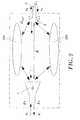
- the setup can be considered as a cuadripole or two-port network, as shown in Fig 2 , illustrating the radiating first antenna 1 (gain G T ), the antenna under test 2 (gain G AUT , load Z L ), and two obstacles 200 that contribute to scattered radiation. Therefore, studying the cuadripole following the common microwave theory (cf. for example, David M.
- the measured reflection factor ⁇ 1 at the input port of the calibrated first antenna 1 is composed by three different contributions, namely:
Landscapes
- Physics & Mathematics (AREA)
- Electromagnetism (AREA)
- General Physics & Mathematics (AREA)
- Variable-Direction Aerials And Aerial Arrays (AREA)
Priority Applications (1)
| Application Number | Priority Date | Filing Date | Title |
|---|---|---|---|
| EP07108888A EP1995599A1 (de) | 2007-05-24 | 2007-05-24 | Verfahren zur Bestimmung eines Antennenparameters |
Applications Claiming Priority (1)
| Application Number | Priority Date | Filing Date | Title |
|---|---|---|---|
| EP07108888A EP1995599A1 (de) | 2007-05-24 | 2007-05-24 | Verfahren zur Bestimmung eines Antennenparameters |
Publications (1)
| Publication Number | Publication Date |
|---|---|
| EP1995599A1 true EP1995599A1 (de) | 2008-11-26 |
Family
ID=38328313
Family Applications (1)
| Application Number | Title | Priority Date | Filing Date |
|---|---|---|---|
| EP07108888A Withdrawn EP1995599A1 (de) | 2007-05-24 | 2007-05-24 | Verfahren zur Bestimmung eines Antennenparameters |
Country Status (1)
| Country | Link |
|---|---|
| EP (1) | EP1995599A1 (de) |
Cited By (6)
| Publication number | Priority date | Publication date | Assignee | Title |
|---|---|---|---|---|
| DE102010033325A1 (de) * | 2010-08-04 | 2012-02-09 | Siemens Aktiengesellschaft | Verfahren zur Vermessung einer Antenne |
| CN113533864A (zh) * | 2021-07-01 | 2021-10-22 | 北京邮电大学 | 一种三反射镜紧缩场天线测量系统及结构和参数确定方法 |
| CN113676265A (zh) * | 2021-08-11 | 2021-11-19 | 中国电波传播研究所(中国电子科技集团公司第二十二研究所) | 一种确定有源单极天线功率增益的方法 |
| CN114034938A (zh) * | 2021-11-05 | 2022-02-11 | 青岛大学 | 一种介质空间中天线性能评估方法、装置及电子设备 |
| TWI847639B (zh) * | 2023-03-29 | 2024-07-01 | 中華電信股份有限公司 | 基於近場到遠場轉換的天線場型的測量裝置和測量方法 |
| FR3155599A1 (fr) * | 2023-11-21 | 2025-05-23 | Commissariat A L'energie Atomique Et Aux Energies Alternatives | Système et procédé de caractérisation par réflexion d’un système antennaire comprenant une pluralité de ports d’entrée/sortie |
Citations (1)
| Publication number | Priority date | Publication date | Assignee | Title |
|---|---|---|---|---|
| US5410324A (en) * | 1991-03-14 | 1995-04-25 | Centre National De La Recherche Scientifique | Method and apparatus for determining antenna radiation patterns |
-
2007
- 2007-05-24 EP EP07108888A patent/EP1995599A1/de not_active Withdrawn
Patent Citations (1)
| Publication number | Priority date | Publication date | Assignee | Title |
|---|---|---|---|---|
| US5410324A (en) * | 1991-03-14 | 1995-04-25 | Centre National De La Recherche Scientifique | Method and apparatus for determining antenna radiation patterns |
Cited By (9)
| Publication number | Priority date | Publication date | Assignee | Title |
|---|---|---|---|---|
| DE102010033325A1 (de) * | 2010-08-04 | 2012-02-09 | Siemens Aktiengesellschaft | Verfahren zur Vermessung einer Antenne |
| CN113533864A (zh) * | 2021-07-01 | 2021-10-22 | 北京邮电大学 | 一种三反射镜紧缩场天线测量系统及结构和参数确定方法 |
| CN113533864B (zh) * | 2021-07-01 | 2022-07-29 | 北京邮电大学 | 一种三反射镜紧缩场天线测量系统及结构和参数确定方法 |
| CN113676265A (zh) * | 2021-08-11 | 2021-11-19 | 中国电波传播研究所(中国电子科技集团公司第二十二研究所) | 一种确定有源单极天线功率增益的方法 |
| CN113676265B (zh) * | 2021-08-11 | 2023-06-23 | 中国电波传播研究所(中国电子科技集团公司第二十二研究所) | 一种确定有源单极天线功率增益的方法 |
| CN114034938A (zh) * | 2021-11-05 | 2022-02-11 | 青岛大学 | 一种介质空间中天线性能评估方法、装置及电子设备 |
| CN114034938B (zh) * | 2021-11-05 | 2023-12-05 | 青岛大学 | 一种介质空间中天线性能评估方法、装置及电子设备 |
| TWI847639B (zh) * | 2023-03-29 | 2024-07-01 | 中華電信股份有限公司 | 基於近場到遠場轉換的天線場型的測量裝置和測量方法 |
| FR3155599A1 (fr) * | 2023-11-21 | 2025-05-23 | Commissariat A L'energie Atomique Et Aux Energies Alternatives | Système et procédé de caractérisation par réflexion d’un système antennaire comprenant une pluralité de ports d’entrée/sortie |
Similar Documents
| Publication | Publication Date | Title |
|---|---|---|
| US9699678B2 (en) | Plane wave generation within a small volume of space for evaluation of wireless devices | |
| Scheers et al. | Time-domain simulation and characterisation of TEM horns using a normalised impulse response | |
| KR101360280B1 (ko) | 흡수재를 구비하지 않은 다중채널 근접장 측정 시스템 | |
| CN109884407B (zh) | 电磁屏蔽效能测量系统及测量方法 | |
| KR101939758B1 (ko) | 안테나 성능 측정 방법 | |
| Khotimah et al. | Design of dipole antenna model for partial discharge detection in GIS | |
| Tice et al. | Probes for microwave near-field measurements | |
| Budka et al. | A coaxial 0.5-18 GHz near electric field measurement system for planar microwave circuits using integrated probes | |
| Pursula et al. | Antenna effective aperture measurement with backscattering modulation | |
| Fourestié et al. | Anechoic chamber evaluation using the matrix pencil method | |
| Ishii et al. | Impedance method for a shielded standard loop antenna | |
| Monteverde et al. | Source stirring technique for reverberation chambers; experimental investigation | |
| Paoletti | On the noise path determination with the noise source modulation technique | |
| Hirose et al. | Antenna measurements by one-path two-port calibration using radio-on-fiber extended port without power supply | |
| JPH06160449A (ja) | 電磁界に対する物体の影響の測定装置 | |
| Wang et al. | MIMO Performance and Uncertainty Analysis in a Reverberation Chamber With Phase Stirring | |
| Bhattacharya et al. | Analysis of rectangular waveguides and thick windows as EMI sensors | |
| Kurokawa | Antenna Measurement | |
| Gapillout et al. | Evaluations of the vector electric field under a wideband transmitting conical antenna | |
| CN219225073U (zh) | 目标物rcs的准确度验证系统 | |
| Azaro et al. | MST probes for electromagnetic fields measurements for EMC applications | |
| Saccardi et al. | Measurement of Transmit and Receive Characteristics of Electrically Large Active Antennas in Spherical Near Field Systems | |
| De Leo et al. | Calibration of a reverberation chamber for radiated emission measurements by wall mounted antennas | |
| Murano et al. | Application of rotating-EM field to four-septum TEM cell for radiated immunity/susceptibility test | |
| JPH06347497A (ja) | アンテナの評価試験装置 |
Legal Events
| Date | Code | Title | Description |
|---|---|---|---|
| PUAI | Public reference made under article 153(3) epc to a published international application that has entered the european phase |
Free format text: ORIGINAL CODE: 0009012 |
|
| AK | Designated contracting states |
Kind code of ref document: A1 Designated state(s): AT BE BG CH CY CZ DE DK EE ES FI FR GB GR HU IE IS IT LI LT LU LV MC MT NL PL PT RO SE SI SK TR |
|
| AX | Request for extension of the european patent |
Extension state: AL BA HR MK RS |
|
| AKX | Designation fees paid | ||
| REG | Reference to a national code |
Ref country code: DE Ref legal event code: 8566 |
|
| STAA | Information on the status of an ep patent application or granted ep patent |
Free format text: STATUS: THE APPLICATION IS DEEMED TO BE WITHDRAWN |
|
| 18D | Application deemed to be withdrawn |
Effective date: 20090527 |