EP1995600B1 - Table de montage et/ou de vérification d'un échantillon - Google Patents
Table de montage et/ou de vérification d'un échantillon Download PDFInfo
- Publication number
- EP1995600B1 EP1995600B1 EP08008651.5A EP08008651A EP1995600B1 EP 1995600 B1 EP1995600 B1 EP 1995600B1 EP 08008651 A EP08008651 A EP 08008651A EP 1995600 B1 EP1995600 B1 EP 1995600B1
- Authority
- EP
- European Patent Office
- Prior art keywords
- adapter
- plug
- signal conductors
- contact elements
- potentials
- Prior art date
- Legal status (The legal status is an assumption and is not a legal conclusion. Google has not performed a legal analysis and makes no representation as to the accuracy of the status listed.)
- Not-in-force
Links
Images





Classifications
-
- G—PHYSICS
- G01—MEASURING; TESTING
- G01R—MEASURING ELECTRIC VARIABLES; MEASURING MAGNETIC VARIABLES
- G01R1/00—Details of instruments or arrangements of the types included in groups G01R5/00 - G01R13/00 and G01R31/00
- G01R1/02—General constructional details
- G01R1/04—Housings; Supporting members; Arrangements of terminals
-
- G—PHYSICS
- G01—MEASURING; TESTING
- G01R—MEASURING ELECTRIC VARIABLES; MEASURING MAGNETIC VARIABLES
- G01R31/00—Arrangements for testing electric properties; Arrangements for locating electric faults; Arrangements for electrical testing characterised by what is being tested not provided for elsewhere
- G01R31/50—Testing of electric apparatus, lines, cables or components for short-circuits, continuity, leakage current or incorrect line connections
- G01R31/58—Testing of lines, cables or conductors
Definitions
- an adapter which is complementary to a connector of a cable and which is provided for connection to an electronic data processing system, the adapter having a memory in which data is stored via the adapter.
- the invention is based on the object to further develop a table for the assembly and testing of a specimen that results in a significant improvement in the qualitative evaluation options of each connected specimens.
- These may be formed by cables and / or a device and / or other object.
- At least one plug-in plate with a plurality of electrically mutually insulated contact elements and at least one modular adapter which is connectable in at least one orientation at any point of the plug at the same time with at least two contact elements, that the contact elements are distributed in a contact element pattern, the regularly and horizontally following one another in a horizontal and vertical direction, that the contact elements are covered by at least two signal conductors insulated against each other with different electrical potentials, that at least two signal conductors with different electrical potentials cross, that the adapter with all potentials is connectable at least once, an identification code and has an internal control that causes a withdrawal of supply current from the signal conductors and their identification and which is suitable with a computer and / or a communicate with other adapters, that the plug-in board and / or the adapter and / or an external computer, each individually and / or in interaction with each other, comprise first means, the recognition of the respective position of the adapter cause the plug-in, that the electrical potentials are distributed to the contact elements in at least
- the contact elements are assigned a rectangular potential pattern and that in the first row at least two mutually different, regularly recurring successive, first potentials are provided and in the second line only a second, regularly recurring Potential.
- the contact elements may also be occupied by a rectangular potential pattern, wherein in the first and second rows there are at least two mutually different, regularly recurring, first potentials with the proviso that the potentials in the first and second rows follow one another in the opposite direction.
- the contact elements can be covered with at least two mutually different, square potential patterns, the potential patterns repeating horizontally and vertically regularly alternately, the potential patterns each comprise four potentials, which are diagonally opposite to each other with identical and, based on each other, with different potentials occupied ,
- the contact elements are covered with two mutually different, square potential patterns, there is the Possibility that the potential patterns are repeated regularly alternately horizontally and vertically, wherein the contact elements contained in the first potential pattern, horizontally juxtaposed with identical and the vertically superimposed contact elements with different potentials, that contained in the second potential pattern, vertically stacked contact elements with identical and horizontally adjacent contact elements with different potentials are occupied, the potentials of the two potential patterns are different from each other.
- each case six contact elements are combined in a contact element pattern, which has the shape of an equilateral hexagon and repeated horizontally and vertically in the manner of a honeycomb.
- At least four contact elements can be combined in the potential pattern, which are distributed on the plug-in plate in a horizontally and vertically regularly repeating, diamond-shaped potential pattern.
- At least two first signal conductors are formed parallel to each other as a signal conductor group and together cross over at least one second signal conductor.
- At least two second signal conductors are arranged to run parallel to one another, they can be designed as a second signal conductor group.
- each signal conductor groups to signal conductors, in which the signal conductors regularly recurring follow each other, the signal conductor groups in first and thus crossing second signal conductor groups regularly recurring alseianderteil, which are distributed over the plug in its entirety.
- the first and the second signal conductors can be assigned to each other at an angle C of 90 °.
- the contact elements may be formed on the side of the plug-in plate by sockets.
- the fixed connection of adapters provided with appropriately positioned and designed plugs is then particularly easy.
- the available signal conductors comprise two signal conductors which have the function of a communication bus. This allows a simple and targeted control of the respective adapter and a mutual communication of the adapter with each other. This can be useful to complete complex inspection tasks.
- the signal conductors may comprise two signal conductors which have the function of a measuring line in order to be able to carry out the required quality measurement of the connected cable and / or device with the aid of the respective adapter.
- the signal conductors may comprise two signal conductors, which have the function of the power supply of the respective adapter. This makes it possible for the to carry out a wide variety of evaluations on the respective test specimens connected.
- At least one adapter is provided with a measuring device for determining the inductance, the voltage, the resistance and / or the capacitance of an electrical conductor connected thereto, e.g. a harness is connected or provided.
- the adapter can thus be supported by a central unit which contains further and / or special measuring devices.
- the resistance determination is e.g. It is still one of the most important evaluations of electrically conductive cables, which at the same time makes it possible to make a statement as to whether a cable is actually connected or not and / or whether short circuits are present.
- At least one adapter for determining the signal attenuation of an optical waveguide may be present.
- Optical fibers are gaining increasing importance in motor vehicles and can therefore also be contained in a cable harness in addition to electrical conductors. Such mixed harnesses are thus also testable, without the need for separate testing facilities.
- the plug-in plate is composed of several plug-in modules and can be enlarged and / or made smaller by attaching and / or removing further plug-in modules as required in the longitudinal and / or transverse direction.
- This makes it possible to form the table cost-effective, for example, depending on the size and shape of each harness to be produced and to use a once-existing basic equipment of plug-in modules and adapters for the production and / or testing of various harnesses and / or objects.
- Wiring harnesses are not only used in motor vehicles Application, but also in everyday electrical appliances, such. B. in kitchen appliances and in consumer electronics.
- a base plate which has either analogous to the plug-in two cross-groups of signal conductors with contact elements to which the plug-in modules can be plugged in that a control contained in each plug-in module is provided with a unique address, which makes it possible to detect the respective position via two signal conductors in interaction with the base plate and to transmit it correctly to a computer connected thereto.
- electronic or electromechanical switches are integrated, which are connected in the sense of the above embodiment, allowing a series query to identify the respective position of the plug-in module.
- the base plate can also be designed as a scaffold, if it is possible to attach the individual plug-in modules to it and to supply it accordingly.
- the number of signal conductors used in the base plate must not be smaller than needed for the operation of the adapter.
- the table can advantageously comprise a modular set of at least one base plate, an adapter and a plug-in module which can be plugged together and released from one another in a computer-controlled manner for the geometrically correct laying and / or testing of a test object.
- the table is particularly suitable for laying and / or testing wire harnesses.
- the geometrically correct assignment of the cables contained in the wiring harness can be controlled by a computer by the to be connected by the respective cable pairs are sequentially marked by displays, for example by a light-emitting diode display or the screen of the computer, a measuring device is provided which, when correctly assigned to each pair of adapters connected by a cable, causes the display to be switched over to the next pair of adapters to be occupied.
- the table can also be used to test specimens that deviate from harnesses, for example for testing shoes, toasters and / or washing machines.
- the adapters are selected and placed computer-controlled on the plug-in board so that the property to be tested is immediately recognized by the adapters and recorded as required, for example the color or the presence of certain accessories.
- the invention provides a freely designable test system that can be reproduced at any time based on a stored in a computer record and put into use.
- plug-in modules used for this purpose can have any basic grid, for example a rectangular or a triangular basic grid.
- plug-in modules preferably arrive within the scope of the invention to the application, which are quadratically limited. You can also be formed diamond-shaped or hexagonal limited.
- the invention can also be used in the form of a module-like built kit of at least one base plate, an adapter and a plug-in module, the computer-controlled assembled and detached from each other for geometrically correct installation, installation and / or testing of a wiring harness as needed, especially during assembly and Testing of test specimens deviating from wiring harnesses.
- the contact elements for the connection of the adapter must be selected so that all available potentials can be connected at least once to the adapter and are available for the control contained therein.
- each adapter first only removes the supply current from the relevant signal conductor and feeds the control contained.
- Each adapter is then properly connected to the potentials required in the board.
- Each adapter also includes an identification code that allows a computer connected to the signal conductors to communicate with each other in a targeted manner.
- the identification code can be stored in a microprocessor.
- the adapter can thus be widely used with considerable possibilities to access it bus - controlled and to make it usable for a variety of tasks in the control of each connected DUTs.
- the examinees can by Cable or any device may be formed or at least contain such.
- the adapter can detect this signal change when the central unit produces a signal state by simple electrical bridging.
- the central processing unit may detect the signal change when the controller of the adapter is producing a signal state, e.g. by simple electrical bridging.
- the control of the adapter can thus its identification code and in interaction with the central unit and plug its position and Detect alignment on the plug-in board and transmit it to a central computer. This makes it possible to achieve optimized positioning and alignment of the adapters also on the basis of experiments, to save them in the computer and to selectively restore them for later use.
- the adapters can thereby be selectively placed with an orientation to the left or right, up or down on the board according to the respective requirement, which simplifies the use when both groups of parallel signal conductors contain a matching number of signal conductors.
- the display can be assigned directly to the adapters and formed for example by at least one light emitting diode. But it is also possible to use a display of a computer, such as a screen.
- a computer offers the possibility to automatically detect both the location of the placement and to display errors and corrective aids, as well as the ability to record measured values, to display and, if necessary, to log.
- the contact elements may be formed on the side of the plug-in plate by sockets. Their practical use is greatly simplified.
- the groups may contain a different or an identical number of signal conductors. Upwards, there are no limits to the areas.
- the in Fig. 1 shown table consists of a base plate and a mounted thereon plug-in plate 15, which is composed of six plug-in modules 2 of rectangular shape and a plurality of electrically mutually insulated contact elements 3.1, on which fixed five adapters 13 by inserting the plug attached thereto in the contact elements 3.1 are, which are designed as contact sockets.
- the table is in this case intended for the installation and / or testing of a wiring harness 1.
- the adapter 13 are contacted by six pins by plugging.
- Each adapter 13 includes any number of mating connectors 3, in this case one to three, which connect to the cable ends of the harness to be tested, as well as a light emitting diode display 14.
- the mating connector 3 are geometrically correct assignment with the cables contained in a wiring harness 1 controlled by a computer, in pairs successively markable by the LED displays 14, wherein a measuring device is provided which causes a correct switching assignment of each pair of connected by a cable mating connector 3 switching the LED display 14 to the next pair to mating mating connector 3 of the adapter 13 ,
- the adapters 13 are plugged in two different orientations at previously freely selected locations on the plug-in plate 15 and at the same time connected with a plurality of contact elements 3.1 signal and / or electrically conductive.
- the correct positioning of the adapter 13 is displayed on the plug-in modules 2 and the positioning of the plug-in modules 2 on the base plate each computer-controlled. The selection depends on the type of measurement to be performed in each case and can also be specified computer-controlled.
- the plug-in plate 15 is composed of the plug-in modules 2 and can be enlarged and / or reduced in size by adding and / or removing further plug-in modules 2 as required in the longitudinal and / or transverse direction. It need not have a rectangular or square outer contour, but it can be designed so that a cable harness to be manufactured or tested is particularly easy to assemble. Since the cables contained therein are flexible, the correct training and measurement is sufficient. On the other hand, it is not necessary to give the cable harness 1 the shape of the installation form during its manufacture.
- the table can thus consist of a module-like construction of at least one adapter 13, a plug-in module 2 and a base plate, the computer-controlled assembled and detached from each other for geometrically correct installation and / or testing of a wiring harness 1 as needed. It can also be mounted only one adapter 13 on a plug-in plate 15.
- the connecting elements of the adapter 13 to the contact elements 3.1 are hereinafter always referred to as contact fields.
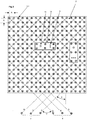
- Fig. 2 is the functional structure of a table shown in a schematic representation. It is shown that all matching contact elements 3.1 are arranged in the course of diagonal signal conductor sets of parallel signal conductors N, O, P and Q, R, S, which form the signal conductor groups 7 and 8, cross each other and at the same time determine the position of the contact elements 3.1, with which they are connected signal-conducting.
- the contact elements 3.1 are arranged in a recurring, square basic grid of the division A. Matching potential assignments of the contact elements 3.1 are consistently patterned and marked.
- the contact elements 3.1 are distributed on the plug-in plate in a square contact element pattern A, which follows in the horizontal and vertical direction regularly recurring, the contact elements 3.1 by several electrically mutually insulated signal conductors N, O, P, Q, R, S with different electrical potentials are occupied, wherein at least two signal conductors N, O, P, Q, R, S intersect with different electrical potentials, each adapter 13 is connected to all potentials at least once, has an identification code and an internal control, which is a withdrawal of supply current from the signal conductors N, O, P, Q, R, S and their identification causes and which is suitable to communicate with a computer and / or another adapter 13, wherein the plug-in plate 15 and / or the adapter 13 and / or a external computer, each for themselves and / or in interaction with each other, first means comprising a detection of the respective effect the position of the adapter 13 on the plug-in plate 15, wherein the electrical potentials are distributed to the contact elements 3.1 in a potential pattern that regularly recurring
- the contact elements 3.1 are by the groups 7, 8 of parallel signal conductors N, O, P; Q, R, S, which are associated with the alignment of the Kontakelementmusters at an angle B of 45 ° and each other at an angle C of 90 °, all signal conductors N, 0, P, Q, R, S of the two groups 7, 8 are occupied by mutually different potentials, wherein the potential assignment of the signal conductors N, O, P and Q, R, S within the two groups 7, 8 changes regularly recurring.
- each contained in the groups 7, 8 signal conductor N, O, P, Q, R, S is in the illustrated embodiment, which is preferred within the scope of the invention, six, the signal conductors N, O, P the basic grid of Sockets 3.1 are associated with right angles and the signal conductors Q, R, S the sockets 3.1 to the left each at an angle of 45 °.
- adapters 13 are also in Fig. 2 only the outlines and the contact fields shown, which can be brought into contact engagement with the contact elements 3.1 of the plug-in modules 2.
- the adapters 13 are parallel to each other by six contact fields with the plug-in modules 2 connected, which are arranged in pairs next to each other. It can be seen that after the
- Plugging the adapter 13 on the plug-in modules 2 in each of the contact fields of each adapter 13 is visible from the other contact fields of different signal conductors N, O, P, Q, R, S.
- all signals of the signal conductors N, O, P, Q, R, S, regardless of the respective mounting position of the respective adapter 13 for each of the adapters 13 are directly available.
- the adapters 13 are provided with signal lights 14 and with a different number of mating contacts 3, which serve to connect specimens.
- the adapters 13 are sized and designed so that all potentials of the signal conductors N, O, P, Q, R, S are available therein.
- the adapters 13 can be plugged onto the sockets 3.1 only with a horizontal or vertical orientation, but not with a diagonally left or right inclined orientation. Incorrect assignments are thereby prevented.
- the signal conductors N, O, P, Q, R, S in the embodiment shown comprise two signal conductors N, O, P, Q, R, S which have the function of a communication bus. They make it possible to properly position and control each adapter 13.
- the signal conductors N, O, P, Q, R, S comprise two signal conductors N, O, P, Q, R, S which have the function of a measuring line. This makes it possible to perform a prescribed measurement of the connected cable and another DUT.
- the signal conductors N, O, P, Q, R, S also comprise two signal conductors N, O, P, Q, R, S, which ensure the function of the power supply of the respective adapter 13 and thereby the start-up and use of the control contained.
- At least one adapter 13 may be provided with a measuring device for determining the resistance or the capacitance of an electrical conductor of the cable harness connected thereto and / or at least one adapter 13 for determining the signal attenuation of an optical waveguide in the cable harness.
- the measuring device is connected for this purpose via two signal conductors and located in the adapters switch of the switch matrix with the DUT.
- Fig. 3 shows that the successive, matching signal conductors N, O, P, Q, R, S are switchable by switch 16.
- the analog Fig. 2 are arranged running, can be found in conjunction with the controller and the identification code of the plugged adapter, at which geometric point of the plug-in board is the respective adapter.
- the location can be reconstructed computer-controlled as needed, as indicated above.
- the orientation can be determined on the basis of the signal assignment by the adapter and transmitted to a computer. Therein, the data can be stored reconstructed.
- Matching potential assignments of the contact elements 3.1 are analog Fig. 2 consistently patterned and marked.
- the same system can also be used in the positioning of the plug-in modules on the base plate, not shown.
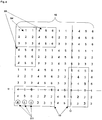
- Fig. 4 shows a first example, according to which the contact elements 3.1 are occupied by a rectangular potential pattern X1, wherein in the first row of the potential pattern X1 at least two mutually different, regularly recurring potentials 1, 2 are provided and in the second row only a second regularly recurrent potential 3.
- all potentials 1 to 3 are available regardless of the mounting position and orientation. He is thereby functional and usable.
- Fig. 5 shows contact elements 3.1, which are occupied by a rectangular potential pattern X2, in the first and second rows at least two The first potentials 1, 2, which are different from each other and regularly recurring, comprise with the proviso that the potentials 1, 2 in the first and second rows follow one another in the opposite direction.
- an exemplary adapter 13 three arranged in a row one behind the other contact fields are arranged. Regardless of the mounting position and orientation, they provide all existing potentials 1, 2 for internal control.
- Fig. 6 shows a table in which the contact elements 3.1 are occupied by two mutually different, square potential patterns X2, X3, which regularly repeat alternately horizontally and vertically, the potential pattern X2, X3 each having four potentials, which are diagonally opposite each other with identical and, related to each other, are occupied with different potentials.
- an exemplary adapter 13 five arranged in a row one behind the other contact fields are arranged. Regardless of the mounting position and alignment, they provide all existing potentials 1, 2, 3, 4 for internal control.
- Fig. 7 shows a table in which the contact elements 3.1 are occupied with a uniform potential pattern X6.
- the potential pattern X6 is arranged in the course of straight-line signal conductors N, O, P, Q, R and S, which extend parallel to each other within intersecting signal conductor groups and cross each other at an angle of 90 °.
- the signal conductors N, O, P, Q, R and S follow within the signal conductor groups and the signal conductor groups within signal conductor groups, which are uniformly distributed over the entire plug-in plate 15, regularly recurring to each other.
- the potential pattern X6 there are six potentials 1-6 in the horizontal and vertical directions. The number can vary depending on respective purpose be increased or decreased.
- the respective associated adapter 13 is designed so that all available, here all six potentials are connected and detected at least once by contact fields.
- Fig. 8 shows a table in which the contact elements 3.1 are occupied by two different, square potential patterns X4, X5, which are regularly repeated alternately horizontally and vertically, wherein contained in the potential pattern X4, horizontally adjacent contact elements 3.1 with identical and the vertical superimposed contact elements 3.1 with different potentials 1 - 6 are occupied, wherein the contained in the potential pattern X5, vertically stacked contact elements 3.1 are occupied with identical and horizontally adjacent contact elements 3.1 with different potentials and the potentials of the potential patterns X4 and X5 different from each other are.
- the contact fields of the adapters 13 provide, independently of the mounting position and orientation, all available potentials 1, 2, 3, 4, 5, 6 for the internal control. Only two cross-over signal conductors N, Q representative of the total of six existing signal conductors N, O, P, Q, R and S were entered.
- Fig. 9 shows a table in which six contact elements 3.1 are summarized in a contact element pattern, which has the shape of an equilateral hexagon and repeated horizontally and vertically in the manner of a honeycomb.
- the contact elements follow each other within the structure of the hexagon shown so that regardless of the mounting position of an adapter always all six potentials 1 to 6 are available.
- These are fed via signal conductors N, O and P and signal conductors Q, R and S which cross each other, each one group form and run parallel to each other within the groups and follow each other at regular intervals.
- the groups form constituents of signal conductor shares which cross one another and are distributed uniformly over the entire plug-in plate. They can also form components of printed circuits, which are arranged behind the plug-in plate 15.
- the contact fields of the adapters 13 also provide all available potentials 1 to 6 for the internal control independently of the mounting position.
- Fig. 10 shows a table in which four contact elements 3.1 are summarized in a potential pattern such that the contact elements 3.1 distributed on the plug-in plate 15 in a horizontally and vertically regularly repeating, diamond-shaped potential pattern X7 and each are assigned to each gap so that the basic structure an equilateral triangle.
- the adapters 13 are in turn dimensioned and designed such that all potentials 1-4 are available at least once for the internal control. They are connected via signal conductors N, O; Q, R, which cross each other in pairs, extend parallel to each other within the pairs and form components of signal sets, which are distributed uniformly over the entire board. In this case, the contact fields of the adapters 13 also provide all available potentials 1 to 4 for the internal control independently of the mounting position.
Landscapes
- Physics & Mathematics (AREA)
- General Physics & Mathematics (AREA)
- Coupling Device And Connection With Printed Circuit (AREA)
- Measuring Leads Or Probes (AREA)
Claims (7)
- Table pour le montage et la vérification d'un échantillon (1), constituée d'au moins une plaque d'enfichage (15) avec une pluralité d'éléments de contact (3.1) mutuellement isolés électriquement et d'au moins un adaptateur (13) modulaire qui présente une pluralité d'éléments de raccordement afin de pouvoir être agencé dans au moins une orientation sur chacune d'une pluralité de positions quelconques de la plaque d'enfichage (15) de sorte que l'adaptateur (13) puisse être relié par conduction dans chacun des agencements par le biais des éléments de raccordement en même temps à au moins deux éléments de contact (3.1) dans l'agencement respectif, dans laquelle l'agencement est défini par l'orientation et la position dans laquelle l'adaptateur est agencé,
dans laquelle pour chacun des agencements par un enfichage de l'adaptateur (13) sur la plaque d'enfichage une liaison conductrice de l'adaptateur peut être établie avec les au moins deux éléments de contact (3.1) respectifs,
dans laquelle la table est configurée de sorte
que les éléments de contact (3.1) soient répartis dans un motif d'éléments de contact qui s'enchaîne dans une direction horizontale et une direction verticale en se répétant régulièrement, dans laquelle la direction horizontale et la direction verticale sont parallèles à la plaque d'enfichage ;
dans laquelle chacun des éléments de contact (3.1) est respectivement relié à un d'au moins deux conducteurs de signal mutuellement isolés électriquement de la table, de sorte que les éléments de contact soient occupés par les au moins deux conducteurs de signal (N, O, P, Q, R, S) avec différents potentiels électriques (1-6), et de sorte que les différents potentiels électriques (1-6) soient répartis sur les éléments de contact (3.1) dans au moins un motif de potentiels (X1, X2, X3, X4, X5, X6, X7) qui suit dans la direction horizontale et la direction verticale en se répétant régulièrement,
que l'adaptateur (13) puisse être relié au moins une fois dans chacun des agencements par la liaison conductrice avec les au moins deux éléments de contact respectifs à tous les potentiels, dans laquelle les potentiels (1-6) génèrent dans chacun des agencements une occupation de potentiel des éléments de raccordement, laquelle dépend de l'agencement de l'adaptateur ;
que l'adaptateur (13) possède un code d'identification,
que l'adaptateur (13) possède une commande interne qui provoque dans chacun des agencements après la liaison avec les au moins deux éléments de contact dans l'agencement respectif un prélèvement de courant d'alimentation des conducteurs de signal (N, O, P, Q, R, S),
que la commande présente un circuit pour l'identification des conducteurs de signal qui sont reliés aux éléments de raccordement, et pour l'établissement d'une véritable liaison de l'adaptateur avec tous les potentiels des conducteurs de signal, de sorte que tous les potentiels des conducteurs de signal soient disponibles pour l'adaptateur indépendamment de l'agencement respectif de l'adaptateur ;
dans laquelle la commande est configurée afin de communiquer avec un ordinateur et/ou un autre adaptateur (13),
que la plaque d'enfichage (15) et/ou l'adaptateur (13) et/ou un ordinateur externe comprennent, chacun pour soi et/ou en interaction les uns avec les autres, de premiers moyens qui provoquent une reconnaissance de la position respective de l'adaptateur (13) sur la plaque d'enfichage (15),
que chaque adaptateur (13) puisse être mis en prise avec l'échantillon (1) et comprenne des moyens qui soutiennent et/ou provoquent le montage et la vérification de l'échantillon (1). - Table selon la revendication 1, caractérisée en ce que les conducteurs de signal (N, O, P, Q, R, S) comprennent deux conducteurs de signal (N, O, P, Q, R, S) qui assurent la fonction d'un bus de communication.
- Table selon la revendication 1 ou 2, caractérisée en ce que les conducteurs de signal (N, O, P, Q, R, S) comprennent deux conducteurs de signal (N, O, P, Q, R, S) qui assurent la fonction d'une ligne de mesure.
- Table selon l'une des revendications précédentes, caractérisée en ce que les conducteurs de signal (N, O, P, Q, R, S) comprennent deux conducteurs de signal (N, O, P, Q, R, S) qui assurent la fonction de l'alimentation en courant de l'adaptateur (13) respectif.
- Table selon l'une des revendications précédentes, caractérisée en ce que la plaque d'enfichage (15) est composée de plusieurs modules d'enfichage (2) et peut être agrandie et/ou réduite par ajout et/ou retrait d'autres modules d'enfichage (2) si besoin dans la direction longitudinale et/ou transversale.
- Table selon la revendication 5, caractérisée en ce que les modules d'enfichage (2) sont délimités de manière carrée, rhombique ou hexagonale.
- Table selon l'une des revendications précédentes, comprenant un kit constitué comme un module d'au moins une plaque de base, un adaptateur (13) et un module d'enfichage (2) qui sont emboîtables et détachables les uns des autres par commande informatique si besoin pour la pose, le montage et la vérification géométriquement corrects d'un faisceau de câbles (1).
Applications Claiming Priority (1)
| Application Number | Priority Date | Filing Date | Title |
|---|---|---|---|
| DE102007024601A DE102007024601B3 (de) | 2007-05-25 | 2007-05-25 | Tisch für die Montage und/oder Prüfung eines Prüflings |
Publications (2)
| Publication Number | Publication Date |
|---|---|
| EP1995600A1 EP1995600A1 (fr) | 2008-11-26 |
| EP1995600B1 true EP1995600B1 (fr) | 2018-02-07 |
Family
ID=39718955
Family Applications (1)
| Application Number | Title | Priority Date | Filing Date |
|---|---|---|---|
| EP08008651.5A Not-in-force EP1995600B1 (fr) | 2007-05-25 | 2008-05-08 | Table de montage et/ou de vérification d'un échantillon |
Country Status (2)
| Country | Link |
|---|---|
| EP (1) | EP1995600B1 (fr) |
| DE (1) | DE102007024601B3 (fr) |
Families Citing this family (1)
| Publication number | Priority date | Publication date | Assignee | Title |
|---|---|---|---|---|
| DE102011101467B4 (de) * | 2011-05-13 | 2015-09-10 | Engberts Mess-, Steuer- Und Regelsysteme Gmbh | Verfahren zum prüfen und herstellen einer elektrischen schaltung |
Citations (1)
| Publication number | Priority date | Publication date | Assignee | Title |
|---|---|---|---|---|
| WO2001079871A1 (fr) * | 2000-04-18 | 2001-10-25 | Wee Electrotest Engineering Gmbh | Procede et dispositif pour le controle de faisceaux de cables |
Family Cites Families (10)
| Publication number | Priority date | Publication date | Assignee | Title |
|---|---|---|---|---|
| DE3940070A1 (de) | 1989-12-04 | 1991-06-06 | Eybaecher Elektronik Systeme M | Vorrichtung zum aufbauen und pruefen von leitungssystemen |
| JP3189918B2 (ja) | 1993-03-02 | 2001-07-16 | 矢崎総業株式会社 | ワイヤハーネス検査装置 |
| DE4436354A1 (de) * | 1994-10-12 | 1996-04-25 | Hanno Link | Vorrichtung zum gleichzeitigen Prüfen einer Mehrzahl von elektrischen oder elektronischen Teilen |
| DE19500113C2 (de) * | 1995-01-04 | 1996-03-28 | Klaus Wurmhoeringer | Kabeltestadapter |
| DE29920214U1 (de) * | 1999-11-17 | 2000-01-20 | TSK Prüfsysteme für elektrische Komponenten GmbH, 32457 Porta Westfalica | Einrichtung zum Testen von mit Steckern versehenen Kabeln |
| DE10019860C1 (de) * | 2000-04-18 | 2001-10-31 | Wee Electrotest Engineering Gm | Verfahren und Einrichtung zum Prüfen von Kabelbäumen |
| JP3988406B2 (ja) * | 2001-05-30 | 2007-10-10 | 住友電装株式会社 | 電気配線システムの検査装置及び方法 |
| US6718284B2 (en) * | 2002-01-30 | 2004-04-06 | Cirris Systems Corporation | Smart module and adapter apparatus |
| DE10218411A1 (de) * | 2002-04-24 | 2003-11-13 | Engberts Mes Steuer Und Regels | Werkzeug für die Fertigung von Kabelbäumen |
| JP2006292405A (ja) * | 2005-04-06 | 2006-10-26 | Mitsubishi Cable Ind Ltd | ワイヤハーネス検査装置 |
-
2007
- 2007-05-25 DE DE102007024601A patent/DE102007024601B3/de not_active Expired - Fee Related
-
2008
- 2008-05-08 EP EP08008651.5A patent/EP1995600B1/fr not_active Not-in-force
Patent Citations (1)
| Publication number | Priority date | Publication date | Assignee | Title |
|---|---|---|---|---|
| WO2001079871A1 (fr) * | 2000-04-18 | 2001-10-25 | Wee Electrotest Engineering Gmbh | Procede et dispositif pour le controle de faisceaux de cables |
Also Published As
| Publication number | Publication date |
|---|---|
| DE102007024601B3 (de) | 2008-12-24 |
| EP1995600A1 (fr) | 2008-11-26 |
Similar Documents
| Publication | Publication Date | Title |
|---|---|---|
| DE60030707T2 (de) | Ein system um verbindungsmuster von datatoren zu überwachen | |
| DE4438802C1 (de) | Verteilerleisten mit Querverteilung der elektrischen Leistung (II) | |
| DE19960112B4 (de) | Testanordnung zum Testen von Rückwandplatinen, Zwischenträgersubstraten, oder bestückten Leiterplatten | |
| DE2319011C2 (de) | Verfahren zum Prüfen eines Leiternetzes auf einem isolierenden Substrat und Anordnung zur Durchführung des Verfahrens | |
| EP1057038B1 (fr) | Procede et dispositif pour le test de cartes imprimees | |
| EP2652962A1 (fr) | Puce de circuit intégré de contrôle pour unité de gestion de batterie | |
| DE2241738C3 (de) | Rangierverteiler für Alarmanlagen | |
| AT409675B (de) | Überwachungssystem für nh-sicherungssysteme | |
| EP0145830B1 (fr) | Rangée de lames de contact pour un dispositif de test pour circuits imprimés contrôlé par un processeur | |
| DE102009031892B4 (de) | Prüfsystem zum Prüfen einer Leitungsanordnung, Verwendung eines Adapters in einem Prüfsystem und Prüfgerät zum Prüfen einer Leitungsanordnung sowie Verfahren zum Herstellen einer Leitungsanordnung | |
| DE1233038B (de) | Elektrisches Geraet, bei dem die elektrischen Verbindungen zwischen seinen Bauelementen mittels Schaltungsplatten hergestellt sind | |
| DE102011101467B4 (de) | Verfahren zum prüfen und herstellen einer elektrischen schaltung | |
| EP1995600B1 (fr) | Table de montage et/ou de vérification d'un échantillon | |
| DE69008217T2 (de) | System zum Prüfen von Kabelstücken. | |
| WO2013029967A1 (fr) | Dispositif de contrôle du câblage pour des armoires électroniques avec câblage interne de signalisation | |
| DE112005002723T5 (de) | System zur Herstellungsprüfung und Programmierung | |
| DE2954194C2 (de) | Adapter zum Anschluß von eine Vielzahl von rasterartig verteilten Anschlußpunkten aufweisenden Prüflingen | |
| DE3414968C2 (de) | Verfahren zur Ermittlung der unbekannten Zuordnung von Feldkoordinaten der Kontaktnadeln eines Kontaktnadelfeldes eines Prüflingsadapters zu den Adressen der Kontaktnadeln in einem Verdrahtungs-Prüfautomaten | |
| AT379246B (de) | Schaltplatte zum aufbau und zur demonstration von elektrischen oder elektronischen schaltungen mit einer arbeitsplatte | |
| DE2948620C2 (de) | Schaltplatte zum Aufbau und zur Demonstration von elektrischen oder elektronischen Schaltungen | |
| DE2127986C3 (de) | Lehrvorrichtung | |
| EP1083434A2 (fr) | Appareil pour tester des plaquettes de circuits imprimés | |
| DE2821821C2 (de) | Anordnung zur Nachbildung der Baugruppenvollständigkeit bei minderausgebauten Funktionseinrichtungen | |
| DE19836479C5 (de) | Türanlage, insbesondere Türsprechanlage | |
| DE10149502A1 (de) | Vorrichtung zum Prüfen elektrischer Leitungen |
Legal Events
| Date | Code | Title | Description |
|---|---|---|---|
| PUAI | Public reference made under article 153(3) epc to a published international application that has entered the european phase |
Free format text: ORIGINAL CODE: 0009012 |
|
| AK | Designated contracting states |
Kind code of ref document: A1 Designated state(s): AT BE BG CH CY CZ DE DK EE ES FI FR GB GR HR HU IE IS IT LI LT LU LV MC MT NL NO PL PT RO SE SI SK TR |
|
| AX | Request for extension of the european patent |
Extension state: AL BA MK RS |
|
| 17P | Request for examination filed |
Effective date: 20081205 |
|
| AKX | Designation fees paid |
Designated state(s): AT BE BG CH CY CZ DE DK EE ES FI FR GB GR HR HU IE IS IT LI LT LU LV MC MT NL NO PL PT RO SE SI SK TR |
|
| 17Q | First examination report despatched |
Effective date: 20150617 |
|
| GRAP | Despatch of communication of intention to grant a patent |
Free format text: ORIGINAL CODE: EPIDOSNIGR1 |
|
| GRAJ | Information related to disapproval of communication of intention to grant by the applicant or resumption of examination proceedings by the epo deleted |
Free format text: ORIGINAL CODE: EPIDOSDIGR1 |
|
| GRAP | Despatch of communication of intention to grant a patent |
Free format text: ORIGINAL CODE: EPIDOSNIGR1 |
|
| INTG | Intention to grant announced |
Effective date: 20170829 |
|
| GRAS | Grant fee paid |
Free format text: ORIGINAL CODE: EPIDOSNIGR3 |
|
| GRAA | (expected) grant |
Free format text: ORIGINAL CODE: 0009210 |
|
| AK | Designated contracting states |
Kind code of ref document: B1 Designated state(s): AT BE BG CH CY CZ DE DK EE ES FI FR GB GR HR HU IE IS IT LI LT LU LV MC MT NL NO PL PT RO SE SI SK TR |
|
| REG | Reference to a national code |
Ref country code: GB Ref legal event code: FG4D Free format text: NOT ENGLISH |
|
| REG | Reference to a national code |
Ref country code: AT Ref legal event code: REF Ref document number: 969002 Country of ref document: AT Kind code of ref document: T Effective date: 20180215 Ref country code: CH Ref legal event code: EP |
|
| REG | Reference to a national code |
Ref country code: IE Ref legal event code: FG4D Free format text: LANGUAGE OF EP DOCUMENT: GERMAN |
|
| REG | Reference to a national code |
Ref country code: DE Ref legal event code: R096 Ref document number: 502008015887 Country of ref document: DE |
|
| REG | Reference to a national code |
Ref country code: FR Ref legal event code: PLFP Year of fee payment: 11 |
|
| REG | Reference to a national code |
Ref country code: NL Ref legal event code: MP Effective date: 20180207 |
|
| PG25 | Lapsed in a contracting state [announced via postgrant information from national office to epo] |
Ref country code: NL Free format text: LAPSE BECAUSE OF FAILURE TO SUBMIT A TRANSLATION OF THE DESCRIPTION OR TO PAY THE FEE WITHIN THE PRESCRIBED TIME-LIMIT Effective date: 20180207 Ref country code: ES Free format text: LAPSE BECAUSE OF FAILURE TO SUBMIT A TRANSLATION OF THE DESCRIPTION OR TO PAY THE FEE WITHIN THE PRESCRIBED TIME-LIMIT Effective date: 20180207 Ref country code: LT Free format text: LAPSE BECAUSE OF FAILURE TO SUBMIT A TRANSLATION OF THE DESCRIPTION OR TO PAY THE FEE WITHIN THE PRESCRIBED TIME-LIMIT Effective date: 20180207 Ref country code: NO Free format text: LAPSE BECAUSE OF FAILURE TO SUBMIT A TRANSLATION OF THE DESCRIPTION OR TO PAY THE FEE WITHIN THE PRESCRIBED TIME-LIMIT Effective date: 20180507 Ref country code: HR Free format text: LAPSE BECAUSE OF FAILURE TO SUBMIT A TRANSLATION OF THE DESCRIPTION OR TO PAY THE FEE WITHIN THE PRESCRIBED TIME-LIMIT Effective date: 20180207 Ref country code: CY Free format text: LAPSE BECAUSE OF FAILURE TO SUBMIT A TRANSLATION OF THE DESCRIPTION OR TO PAY THE FEE WITHIN THE PRESCRIBED TIME-LIMIT Effective date: 20180207 Ref country code: FI Free format text: LAPSE BECAUSE OF FAILURE TO SUBMIT A TRANSLATION OF THE DESCRIPTION OR TO PAY THE FEE WITHIN THE PRESCRIBED TIME-LIMIT Effective date: 20180207 |
|
| PG25 | Lapsed in a contracting state [announced via postgrant information from national office to epo] |
Ref country code: IS Free format text: LAPSE BECAUSE OF FAILURE TO SUBMIT A TRANSLATION OF THE DESCRIPTION OR TO PAY THE FEE WITHIN THE PRESCRIBED TIME-LIMIT Effective date: 20180607 Ref country code: PL Free format text: LAPSE BECAUSE OF FAILURE TO SUBMIT A TRANSLATION OF THE DESCRIPTION OR TO PAY THE FEE WITHIN THE PRESCRIBED TIME-LIMIT Effective date: 20180207 Ref country code: GR Free format text: LAPSE BECAUSE OF FAILURE TO SUBMIT A TRANSLATION OF THE DESCRIPTION OR TO PAY THE FEE WITHIN THE PRESCRIBED TIME-LIMIT Effective date: 20180508 Ref country code: BG Free format text: LAPSE BECAUSE OF FAILURE TO SUBMIT A TRANSLATION OF THE DESCRIPTION OR TO PAY THE FEE WITHIN THE PRESCRIBED TIME-LIMIT Effective date: 20180507 Ref country code: SE Free format text: LAPSE BECAUSE OF FAILURE TO SUBMIT A TRANSLATION OF THE DESCRIPTION OR TO PAY THE FEE WITHIN THE PRESCRIBED TIME-LIMIT Effective date: 20180207 Ref country code: LV Free format text: LAPSE BECAUSE OF FAILURE TO SUBMIT A TRANSLATION OF THE DESCRIPTION OR TO PAY THE FEE WITHIN THE PRESCRIBED TIME-LIMIT Effective date: 20180207 |
|
| PG25 | Lapsed in a contracting state [announced via postgrant information from national office to epo] |
Ref country code: MT Free format text: LAPSE BECAUSE OF FAILURE TO SUBMIT A TRANSLATION OF THE DESCRIPTION OR TO PAY THE FEE WITHIN THE PRESCRIBED TIME-LIMIT Effective date: 20180207 |
|
| PG25 | Lapsed in a contracting state [announced via postgrant information from national office to epo] |
Ref country code: IT Free format text: LAPSE BECAUSE OF FAILURE TO SUBMIT A TRANSLATION OF THE DESCRIPTION OR TO PAY THE FEE WITHIN THE PRESCRIBED TIME-LIMIT Effective date: 20180207 Ref country code: RO Free format text: LAPSE BECAUSE OF FAILURE TO SUBMIT A TRANSLATION OF THE DESCRIPTION OR TO PAY THE FEE WITHIN THE PRESCRIBED TIME-LIMIT Effective date: 20180207 Ref country code: EE Free format text: LAPSE BECAUSE OF FAILURE TO SUBMIT A TRANSLATION OF THE DESCRIPTION OR TO PAY THE FEE WITHIN THE PRESCRIBED TIME-LIMIT Effective date: 20180207 |
|
| REG | Reference to a national code |
Ref country code: DE Ref legal event code: R097 Ref document number: 502008015887 Country of ref document: DE |
|
| PG25 | Lapsed in a contracting state [announced via postgrant information from national office to epo] |
Ref country code: DK Free format text: LAPSE BECAUSE OF FAILURE TO SUBMIT A TRANSLATION OF THE DESCRIPTION OR TO PAY THE FEE WITHIN THE PRESCRIBED TIME-LIMIT Effective date: 20180207 Ref country code: CZ Free format text: LAPSE BECAUSE OF FAILURE TO SUBMIT A TRANSLATION OF THE DESCRIPTION OR TO PAY THE FEE WITHIN THE PRESCRIBED TIME-LIMIT Effective date: 20180207 Ref country code: SK Free format text: LAPSE BECAUSE OF FAILURE TO SUBMIT A TRANSLATION OF THE DESCRIPTION OR TO PAY THE FEE WITHIN THE PRESCRIBED TIME-LIMIT Effective date: 20180207 |
|
| PLBE | No opposition filed within time limit |
Free format text: ORIGINAL CODE: 0009261 |
|
| REG | Reference to a national code |
Ref country code: CH Ref legal event code: PL |
|
| STAA | Information on the status of an ep patent application or granted ep patent |
Free format text: STATUS: NO OPPOSITION FILED WITHIN TIME LIMIT |
|
| 26N | No opposition filed |
Effective date: 20181108 |
|
| REG | Reference to a national code |
Ref country code: BE Ref legal event code: MM Effective date: 20180531 |
|
| PG25 | Lapsed in a contracting state [announced via postgrant information from national office to epo] |
Ref country code: MC Free format text: LAPSE BECAUSE OF FAILURE TO SUBMIT A TRANSLATION OF THE DESCRIPTION OR TO PAY THE FEE WITHIN THE PRESCRIBED TIME-LIMIT Effective date: 20180207 |
|
| REG | Reference to a national code |
Ref country code: IE Ref legal event code: MM4A |
|
| PG25 | Lapsed in a contracting state [announced via postgrant information from national office to epo] |
Ref country code: CH Free format text: LAPSE BECAUSE OF NON-PAYMENT OF DUE FEES Effective date: 20180531 Ref country code: LI Free format text: LAPSE BECAUSE OF NON-PAYMENT OF DUE FEES Effective date: 20180531 Ref country code: SI Free format text: LAPSE BECAUSE OF FAILURE TO SUBMIT A TRANSLATION OF THE DESCRIPTION OR TO PAY THE FEE WITHIN THE PRESCRIBED TIME-LIMIT Effective date: 20180207 |
|
| PG25 | Lapsed in a contracting state [announced via postgrant information from national office to epo] |
Ref country code: LU Free format text: LAPSE BECAUSE OF NON-PAYMENT OF DUE FEES Effective date: 20180508 |
|
| PG25 | Lapsed in a contracting state [announced via postgrant information from national office to epo] |
Ref country code: IE Free format text: LAPSE BECAUSE OF NON-PAYMENT OF DUE FEES Effective date: 20180508 |
|
| PG25 | Lapsed in a contracting state [announced via postgrant information from national office to epo] |
Ref country code: BE Free format text: LAPSE BECAUSE OF NON-PAYMENT OF DUE FEES Effective date: 20180531 |
|
| REG | Reference to a national code |
Ref country code: AT Ref legal event code: MM01 Ref document number: 969002 Country of ref document: AT Kind code of ref document: T Effective date: 20180508 |
|
| PG25 | Lapsed in a contracting state [announced via postgrant information from national office to epo] |
Ref country code: AT Free format text: LAPSE BECAUSE OF NON-PAYMENT OF DUE FEES Effective date: 20180508 |
|
| REG | Reference to a national code |
Ref country code: DE Ref legal event code: R079 Ref document number: 502008015887 Country of ref document: DE Free format text: PREVIOUS MAIN CLASS: G01R0031020000 Ipc: G01R0031500000 |
|
| PG25 | Lapsed in a contracting state [announced via postgrant information from national office to epo] |
Ref country code: TR Free format text: LAPSE BECAUSE OF FAILURE TO SUBMIT A TRANSLATION OF THE DESCRIPTION OR TO PAY THE FEE WITHIN THE PRESCRIBED TIME-LIMIT Effective date: 20180207 |
|
| PG25 | Lapsed in a contracting state [announced via postgrant information from national office to epo] |
Ref country code: HU Free format text: LAPSE BECAUSE OF FAILURE TO SUBMIT A TRANSLATION OF THE DESCRIPTION OR TO PAY THE FEE WITHIN THE PRESCRIBED TIME-LIMIT; INVALID AB INITIO Effective date: 20080508 Ref country code: PT Free format text: LAPSE BECAUSE OF FAILURE TO SUBMIT A TRANSLATION OF THE DESCRIPTION OR TO PAY THE FEE WITHIN THE PRESCRIBED TIME-LIMIT Effective date: 20180207 |
|
| PGFP | Annual fee paid to national office [announced via postgrant information from national office to epo] |
Ref country code: DE Payment date: 20210528 Year of fee payment: 14 Ref country code: FR Payment date: 20210528 Year of fee payment: 14 |
|
| PGFP | Annual fee paid to national office [announced via postgrant information from national office to epo] |
Ref country code: GB Payment date: 20210528 Year of fee payment: 14 |
|
| REG | Reference to a national code |
Ref country code: DE Ref legal event code: R119 Ref document number: 502008015887 Country of ref document: DE |
|
| GBPC | Gb: european patent ceased through non-payment of renewal fee |
Effective date: 20220508 |
|
| PG25 | Lapsed in a contracting state [announced via postgrant information from national office to epo] |
Ref country code: FR Free format text: LAPSE BECAUSE OF NON-PAYMENT OF DUE FEES Effective date: 20220531 |
|
| PG25 | Lapsed in a contracting state [announced via postgrant information from national office to epo] |
Ref country code: GB Free format text: LAPSE BECAUSE OF NON-PAYMENT OF DUE FEES Effective date: 20220508 Ref country code: DE Free format text: LAPSE BECAUSE OF NON-PAYMENT OF DUE FEES Effective date: 20221201 |