EP1995659A1 - Support de stockage ayant un programme de traitement d'informations installé et appareil de traitement d'informations - Google Patents
Support de stockage ayant un programme de traitement d'informations installé et appareil de traitement d'informations Download PDFInfo
- Publication number
- EP1995659A1 EP1995659A1 EP07012269A EP07012269A EP1995659A1 EP 1995659 A1 EP1995659 A1 EP 1995659A1 EP 07012269 A EP07012269 A EP 07012269A EP 07012269 A EP07012269 A EP 07012269A EP 1995659 A1 EP1995659 A1 EP 1995659A1
- Authority
- EP
- European Patent Office
- Prior art keywords
- acceleration
- predetermined
- moving direction
- controller
- information processing
- Prior art date
- Legal status (The legal status is an assumption and is not a legal conclusion. Google has not performed a legal analysis and makes no representation as to the accuracy of the status listed.)
- Granted
Links
Images









Classifications
-
- A63F13/10—
-
- A—HUMAN NECESSITIES
- A63—SPORTS; GAMES; AMUSEMENTS
- A63F—CARD, BOARD, OR ROULETTE GAMES; INDOOR GAMES USING SMALL MOVING PLAYING BODIES; VIDEO GAMES; GAMES NOT OTHERWISE PROVIDED FOR
- A63F13/00—Video games, i.e. games using an electronically generated display having two or more dimensions
- A63F13/20—Input arrangements for video game devices
- A63F13/21—Input arrangements for video game devices characterised by their sensors, purposes or types
- A63F13/211—Input arrangements for video game devices characterised by their sensors, purposes or types using inertial sensors, e.g. accelerometers or gyroscopes
-
- A—HUMAN NECESSITIES
- A63—SPORTS; GAMES; AMUSEMENTS
- A63F—CARD, BOARD, OR ROULETTE GAMES; INDOOR GAMES USING SMALL MOVING PLAYING BODIES; VIDEO GAMES; GAMES NOT OTHERWISE PROVIDED FOR
- A63F13/00—Video games, i.e. games using an electronically generated display having two or more dimensions
- A63F13/40—Processing input control signals of video game devices, e.g. signals generated by the player or derived from the environment
- A63F13/42—Processing input control signals of video game devices, e.g. signals generated by the player or derived from the environment by mapping the input signals into game commands, e.g. mapping the displacement of a stylus on a touch screen to the steering angle of a virtual vehicle
- A63F13/428—Processing input control signals of video game devices, e.g. signals generated by the player or derived from the environment by mapping the input signals into game commands, e.g. mapping the displacement of a stylus on a touch screen to the steering angle of a virtual vehicle involving motion or position input signals, e.g. signals representing the rotation of an input controller or a player's arm motions sensed by accelerometers or gyroscopes
-
- A—HUMAN NECESSITIES
- A63—SPORTS; GAMES; AMUSEMENTS
- A63F—CARD, BOARD, OR ROULETTE GAMES; INDOOR GAMES USING SMALL MOVING PLAYING BODIES; VIDEO GAMES; GAMES NOT OTHERWISE PROVIDED FOR
- A63F13/00—Video games, i.e. games using an electronically generated display having two or more dimensions
- A63F13/45—Controlling the progress of the video game
-
- G—PHYSICS
- G06—COMPUTING OR CALCULATING; COUNTING
- G06F—ELECTRIC DIGITAL DATA PROCESSING
- G06F3/00—Input arrangements for transferring data to be processed into a form capable of being handled by the computer; Output arrangements for transferring data from processing unit to output unit, e.g. interface arrangements
- G06F3/01—Input arrangements or combined input and output arrangements for interaction between user and computer
- G06F3/017—Gesture based interaction, e.g. based on a set of recognized hand gestures
-
- G—PHYSICS
- G06—COMPUTING OR CALCULATING; COUNTING
- G06F—ELECTRIC DIGITAL DATA PROCESSING
- G06F3/00—Input arrangements for transferring data to be processed into a form capable of being handled by the computer; Output arrangements for transferring data from processing unit to output unit, e.g. interface arrangements
- G06F3/01—Input arrangements or combined input and output arrangements for interaction between user and computer
- G06F3/03—Arrangements for converting the position or the displacement of a member into a coded form
- G06F3/033—Pointing devices displaced or positioned by the user, e.g. mice, trackballs, pens or joysticks; Accessories therefor
- G06F3/0346—Pointing devices displaced or positioned by the user, e.g. mice, trackballs, pens or joysticks; Accessories therefor with detection of the device orientation or free movement in a three-dimensional [3D] space, e.g. 3D mice, 6-DOF [six degrees of freedom] pointers using gyroscopes, accelerometers or tilt-sensors
-
- A—HUMAN NECESSITIES
- A63—SPORTS; GAMES; AMUSEMENTS
- A63F—CARD, BOARD, OR ROULETTE GAMES; INDOOR GAMES USING SMALL MOVING PLAYING BODIES; VIDEO GAMES; GAMES NOT OTHERWISE PROVIDED FOR
- A63F2300/00—Features of games using an electronically generated display having two or more dimensions, e.g. on a television screen, showing representations related to the game
- A63F2300/10—Features of games using an electronically generated display having two or more dimensions, e.g. on a television screen, showing representations related to the game characterized by input arrangements for converting player-generated signals into game device control signals
- A63F2300/105—Features of games using an electronically generated display having two or more dimensions, e.g. on a television screen, showing representations related to the game characterized by input arrangements for converting player-generated signals into game device control signals using inertial sensors, e.g. accelerometers, gyroscopes
-
- A—HUMAN NECESSITIES
- A63—SPORTS; GAMES; AMUSEMENTS
- A63F—CARD, BOARD, OR ROULETTE GAMES; INDOOR GAMES USING SMALL MOVING PLAYING BODIES; VIDEO GAMES; GAMES NOT OTHERWISE PROVIDED FOR
- A63F2300/00—Features of games using an electronically generated display having two or more dimensions, e.g. on a television screen, showing representations related to the game
- A63F2300/60—Methods for processing data by generating or executing the game program
- A63F2300/6045—Methods for processing data by generating or executing the game program for mapping control signals received from the input arrangement into game commands
Definitions
- the present invention relates to a storage medium having an information processing program stored thereon and an information processing apparatus, and more particularly to a storage medium having an information processing program stored thereon and an information processing apparatus, which are used for executing a process in accordance with data outputted by an acceleration sensor.
- Patent Document 1 Japanese Laid-Open Patent Publication No. 2002-153673 (hereinafter referred to as Patent Document 1), for example, known is a game apparatus which calculates an action of a player throwing a punch, based on data outputted by an acceleration sensor, so as to allow the player to play a boxing game.
- the game apparatus disclosed in Patent Document 1 is structured such that a glove unit functioning as a controller of the game apparatus includes an acceleration sensor which detects an acceleration in three axial directions, that is, a front-rear (Y-axis) direction, a left-right (X-axis) direction, and an up-down (Z-axis) direction.
- the above-described apparatus analyzes an output waveform outputted by the acceleration sensor so as to identify a type of the punch thrown by the player. Specifically, the game apparatus calculates, based on an output waveform represented by the acceleration data detected in the Y-axis direction, a time period from a start of the punch thrown by the player to an end of the same punch. Next, the game apparatus uses output waveforms represented by the acceleration data in the X-axis direction and the acceleration data in the Z-axis direction, respectively, which are obtained in the time period from the start of the punch thrown by the player to the end of the same punch, so as to extract data representing, for example, a maximum value, a minimum value, amplitude, the number of times a peak appears, and an integration value.
- the game apparatus identifies the type of the punch (straight, hook, and upper punches) in accordance with each of the extracted data and a waveform pattern obtained for each of the types of the punches. After the identification of the type of the punch, the game apparatus performs a game process in accordance with the type of the punch having been identified.
- Patent Document 1 basically adopts a drawing using a first person perspective, and displays, straight away, an image showing an enemy character suffering a damage without drawing an image showing the punching motion of the player when it is determined that the punch hits the enemy character.
- the above-described game apparatus represents and displays a punch thrown by a character controlled by the player, it is necessary to render, after the player finishes the punch action, an image representing the punch action based on the type of the punch, and thus the representation and display of the user's action is increasingly delayed.
- an object of the present invention is to provide a storage medium having an information processing program stored thereon and an information processing apparatus which are used for executing a process of quickly representing an action of a user in accordance with data outputted by an acceleration sensor.
- the present invention has the following features to attain the object mentioned above.
- the reference numerals, step numbers and the like in parentheses indicate the correspondence with the embodiment described below in order to aid in understanding the present invention and are not intended to limit the scope of the present invention in any way.
- a first aspect is a storage medium having stored thereon an information processing program executed by a computer (10) of an information processing apparatus (5) which executes a process using acceleration data (Da) outputted by an acceleration sensor (701) for detecting acceleration applied to a predetermined housing (7, 71).
- the information processing program causes the computer to function as an acceleration data acquisition means (an CPU executing step 43, hereinafter describing a step number only), an acceleration determination means (S82 to S89), moving direction calculation means (S48), and a processing means (S49) .
- the acceleration data acquisition means repeatedly acquires the acceleration data.
- the acceleration determination means determines whether an acceleration represented by the acceleration data acquired by the acceleration data acquisition means is an acceleration (Dd) at the time of accelerating, which is applied when the predetermined housing is moved and accelerated in a predetermined direction, or is an acceleration (De) at the time of decelerating, which is applied when the predetermined housing is moved and decelerated in the predetermined direction.
- the moving direction calculation means calculates a moving direction (dir) in which the predetermined housing moves by using the acceleration at the time of decelerating which is determined by the acceleration determination means.
- the processing means performs a predetermined process by using the moving direction calculated by the moving direction calculation means.
- the acceleration determination means includes a first accumulation means (S89), a second accumulation means (S86 to 88), and an attenuation means (S82).
- the first accumulation means accumulates an acceleration (dp ⁇ 0) applied to a predetermined direction of the predetermined housing, by using the acceleration data acquired by the acceleration data acquisition means.
- the second accumulation means accumulates, within a range not exceeding a value accumulated by the first accumulation means, an acceleration (dp>0) applied to a reverse direction of the predetermined direction by using the acceleration data acquired by the acceleration data acquisition means.
- the attenuation means attenuates values accumulated by the first accumulation means and the second accumulation means, each at a predetermined rate (DAMP) .
- the moving direction calculation means calculates the moving direction of the predetermined housing by using a value accumulated by the second accumulation means as the acceleration at the time of decelerating.
- the acceleration determination means further includes an acceleration component calculation means (S83, S84) for calculating respective acceleration components (dp) applied to a plurality of directions (0th to N-1th direction in FIG. 19 ) of the predetermined housing, by using the acceleration data acquired by the acceleration data acquisition means.
- the first accumulation means accumulates acceleration components (dp ⁇ 0; Yes in S85) applied in a forward direction of each of the plurality of directions.
- the second accumulation means accumulates acceleration components (dp ⁇ 0; No in S85) applied in a reverse direction of said each of the plurality of directions within a range not exceeding an accumulated value of the acceleration components applied in the forward direction which is opposite to the reverse direction, the accumulated value being accumulated by the first accumulation means.
- the attenuation means attenuates, at predetermined rates, respectively, values which are accumulated, with respect to said each of the plurality of directions, by the first accumulation means and the second accumulation means.
- the moving direction calculation means calculates the moving direction of the predetermined housing by using a value, which is obtained by summing values respectively accumulated by the second accumulation means with respect to said each of the plurality of directions, as the acceleration at the time of decelerating.
- the acceleration determination means further includes an acceleration component calculation means.
- the acceleration component calculation means calculates acceleration components applied to a plurality of directions of the predetermined housing, by using the acceleration data acquired by the acceleration data acquisition means.
- the first accumulation means accumulates acceleration components applied in a forward direction of each of the plurality of directions.
- the second accumulation means accumulates acceleration components applied in a reverse direction of said each of the plurality of directions within a range not exceeding an accumulated value of the acceleration components applied in the forward direction which is opposite to the reverse direction, the accumulated value being accumulated by the first accumulation means.
- the attenuation means attenuates, at predetermined rates, respectively, values which are accumulated, with respect to said each of the plurality of directions, by the first accumulation means and the second accumulation means.
- the moving direction calculation means calculates the moving direction of the predetermined housing by using a maximum value, among values accumulated by the second accumulation means, as the acceleration at the time of decelerating.
- the acceleration determination means further includes an acceleration component calculation means.
- the acceleration component calculation means calculates acceleration components applied to a plurality of directions of the predetermined housing, by using the acceleration data acquired by the acceleration data acquisition means.
- the acceleration determination means determines whether each of the acceleration components calculated by the acceleration component calculation means is the acceleration at the time of accelerating or the acceleration at the time of decelerating.
- the moving direction calculation means calculates the moving direction of the predetermined housing by using a value which is obtained by summing the acceleration at the time of decelerating determined by the acceleration determination means with respect to each of the plurality of directions.
- the acceleration determination means further includes an acceleration component calculation means.
- the acceleration determination means calculates acceleration components applied to a plurality of directions of the predetermined housing, by using the acceleration data acquired by the acceleration data acquisition means.
- the acceleration determination means determines whether each of the acceleration components calculated by the acceleration component calculation means is the acceleration at the time of accelerating or the acceleration at the time of decelerating.
- the moving direction calculation means calculates the moving direction of the predetermined housing by using a maximum value among the acceleration at the time of decelerating determined by the acceleration determination means.
- the moving direction calculation means calculates the moving direction of the predetermined housing by using the acceleration at the time of decelerating.
- the computer is further caused to function as an elapsed time measuring means (S105, S107).
- the elapsed time measuring means measures an elapsed time (Dh) after the moving direction is calculated by the moving direction calculation means.
- the processing means performs the predetermined process by using the moving direction calculated by the moving direction calculation means when the elapsed time reaches a predetermined time.
- the computer is further caused to function as a predetermined value settingmeans (S104).
- the predetermined value setting means sets, when the magnitude of the acceleration at the time of decelerating becomes larger than the predetermined value, the magnitude of the acceleration at the time of decelerating as a latest predetermined value.
- the predetermined value setting means decreases the predetermined value by a predetermined amount.
- the predetermined value setting means further sets a fixed value previously, in addition to the predetermined value.
- the moving direction calculation means calculates the moving direction of the predetermined housing by using the acceleration at the time of decelerating.
- the computer is further caused to function as a deceleration vector calculation means (S90).
- the deceleration vector calculation means calculates a deceleration vector (Df), which represents a direction in which the predetermined housing is moving at a decelerated rate, by using the acceleration at the time of decelerating determined by the acceleration determination means.
- the moving direction calculation means calculates the moving direction by using the deceleration vector calculated by the deceleration vector calculation means.
- the acceleration determination means includes a first accumulation means, a second accumulation means, and an attenuation means.
- the first accumulation means accumulates an acceleration applied in a predetermined direction of the predetermined housing, by using the acceleration data acquired by the acceleration data acquisition means.
- the second accumulation means accumulates, within a range not exceeding a value accumulated by the first accumulation means, an acceleration applied in a reverse direction of the predetermined direction by using the acceleration data acquired by the acceleration data acquisition means.
- the attenuation means attenuates values accumulated respectively by the first accumulation means and the second accumulation means, each at a predetermined rate.
- the deceleration vector calculation means calculates the deceleration vector by using a value accumulated by the second accumulation means as an accumulated value of the acceleration at the time of decelerating.
- the acceleration determination means further includes an acceleration component calculation means.
- the acceleration component calculation means calculates acceleration components applied to a plurality of directions of the predetermined housing, by using the acceleration data acquired by the acceleration data acquisition means.
- the first accumulation means accumulates acceleration components applied in a forward direction of each of the plurality of directions.
- the second accumulation means accumulates acceleration components applied in a reverse direction of said each of the plurality of directions within a range not exceeding an accumulated value of the acceleration components applied in the forward direction which is opposite to the reverse direction, the accumulated value being accumulated by the first accumulation means.
- the attenuation means attenuates, at predetermined rates, respectively, values which are accumulated, with respect to said each of the plurality of directions, by the first accumulation means and the second accumulation means.
- the deceleration vector calculation means calculates the deceleration vector by summing values accumulated by the second accumulation means with respect to said each of the plurality of directions.
- the acceleration determination means further includes an acceleration component calculation means.
- the acceleration component calculation means calculates acceleration components applied to a plurality of directions of the predetermined housing, by using the acceleration data acquired by the acceleration data acquisition means.
- the first accumulation means accumulates acceleration components applied in a forward direction of each of the plurality of directions.
- the second accumulation means accumulates acceleration components applied in a reverse direction of said each of the plurality of the directions within a range not exceeding an accumulated value of the acceleration components applied in the forward direction which is opposite to the reverse direction, the accumulated value being accumulated by the first accumulated means.
- the attenuation means attenuates, at predetermined rates, respectively, values which are accumulated, with respect to said each of the plurality of directions, by the first accumulation means and the second accumulation means.
- the deceleration vector calculation means calculates the deceleration vector by using a maximum value, among values accumulated by the second accumulation means.
- the computer is further caused to function as a gravity direction calculation means (S44).
- the gravity direction calculation means calculates a direction of a gravity acceleration (Pos) applied to the predetermined housing by using the acceleration data acquired by the acceleration data acquisition means.
- the moving direction calculation means calculates the moving direction relative to the direction of the gravity acceleration being applied in accordance with the direction of the gravity acceleration calculated by the gravity direction calculation means and a direction represented by the deceleration vector.
- the moving direction calculation means calculates a direction of the deceleration vector as the moving direction.
- the computer is further caused to function as a predetermined value setting means.
- the predetermined value setting means sets, when the magnitude of the deceleration vector calculated by the deceleration vector calculation means becomes larger than the predetermined value, the magnitude of the deceleration vector as a new predetermined value.
- the predetermined value setting means decreases the predetermined value by a predetermined amount.
- the predetermined value setting means further sets a previously fixed value, in addition to the predetermined value.
- the moving direction calculation means calculates the direction of the deceleration vector as the moving direction.
- the computer is further caused to function as an elapsed time measuring means.
- the elapsed time measuring means measures an elapsed time after the moving direction is calculated by the moving direction calculation means.
- the processing means performs the predetermined process by using the moving direction calculated by the moving direction calculation means when the elapsed time reaches a predetermined time.
- the acceleration determination means determines the acceleration data representing the acceleration applied to the predetermined direction of the predetermined housing as the acceleration at the time of accelerating, and also determines the acceleration data representing the acceleration applied in the reverse direction of the predetermined direction as the acceleration at the time of decelerating.
- the computer is further caused to function as a gravity component calculation means (S45) and a gravity component elimination means (S46).
- the gravity component calculation means calculates a gravity acceleration component (Db) applied to the predetermined housing by using the acceleration data acquired by the acceleration data acquisition means.
- the gravity component elimination means eliminates the gravity acceleration component, which is calculated by the gravity component calculation means, from the acceleration represented by the acceleration data acquired by the acceleration data acquisition means.
- the acceleration determination means uses an acceleration (Dc) from which the gravity acceleration component has been eliminated by the gravity component eliminated means.
- a twenty-fourth aspect is an information processing apparatus for performing a process using acceleration data outputted by an acceleration sensor which detects an acceleration applied to a predetermined housing.
- the information processing apparatus includes an acceleration data acquisition means, an acceleration determination means, a moving direction calculation means, and a processing means.
- the acceleration data acquisition means acquires the acceleration data repeatedly.
- the acceleration determination means determines whether an acceleration represented by the acceleration data acquired by the acceleration data acquisition means is an acceleration at the time of accelerating, which is applied when the predetermined housing is moved and accelerated in a predetermined direction, or is an acceleration at the time of decelerating, which is applied when the predetermined housing is moved and decelerated in the predetermined direction.
- the moving direction calculation means calculates a moving direction in which the predetermined housing moves by using the acceleration at the time of decelerating which is determined by the acceleration determination means.
- the processing means performs a predetermined process by using the moving direction calculated by the moving direction calculation means.
- positive variables are set by accumulating an acceleration applied in a predetermined direction and an acceleration applied in a reverse direction of the predetermined direction, respectively, and the positive variables are each attenuated at a predetermined rate.
- the variables are controlled such that a variable for the reverse direction does not exceed a variable for the predetermined direction, whereby an acceleration applied at the time of accelerating and an acceleration at the time of decelerating applied immediately after the acceleration are paired up as a set. Accordingly, the acceleration at the time of decelerating can be determined accurately.
- determination of the acceleration at the time of decelerating is performed in a plurality of directions, whereby accuracy in calculating the moving direction of the housing is improved. Further, the acceleration at the time of decelerating with respect to each of the plurality of directions is summed, and thus the moving direction of the housing is not limited to the plurality of directions, but is represented in an analog manner, whereby a most appropriate direction is calculated. Further, even if any one of the plurality of directions has a noise, the direction having the noise will not be misrecognized as the moving direction of the housing.
- determination of the acceleration at the time of decelerating is performed with respect to each of the plurality of directions, whereby accuracy in calculating the moving direction of the housing is increasing improved. Further, by using the acceleration at the time of maximumly decelerating, a process of calculating the moving direction of the housing, among the plurality of directions, can be simplified.
- the moving direction is calculated when the magnitudes of the acceleration at the time of decelerating and the deceleration vector are each larger than a predetermined value, it is possible to prevent the moving direction of the housing from being calculated wrongly.
- the elapsed time after calculating the moving direction can be used as a degree of reliability of the moving direction, and therefore, when a more assured moving direction is to be obtained, a predetermined processing can be performed by using a direction calculated when the elapsed time has reached a predetermined time.
- maximum values representing the magnitudes of the acceleration at the time of decelerating and the deceleration vector are each set as a predetermined value, it is possible to prevent a case where calculation of the moving direction is performed frequently.
- an effect of an acceleration exerted by a force other than movement of the housing such as a gravity acceleration, can be eliminated, whereby it is possible to prevent miscalculation of the moving direction of the housing.
- the deceleration vector representing the moving direction of the housing at a decelerated rate is calculated. Accordingly the moving direction or the waving direction of the housing can be calculated two-dimensionally or three-dimensionally.
- the acceleration in the opposite direction is the acceleration applied at the time of decelerating.
- FIG. 1 is an external view illustrating the game system 1 including a stationary game apparatus 3.
- FIG. 2 is a block diagram illustrating the game apparatus body 5.
- the game system 1 will be described.
- the game system 1 includes a home-use television receiver (hereinafter referred to as a monitor) 2 typifying a display means, and a stationary game apparatus 3 connected to the monitor 2 via a connection cord.
- the monitor 2 includes speakers 2a for outputting, as a sound, a sound signal outputted by the game apparatus body 5.
- the game apparatus 3 includes an optical disc 4 having recorded thereon a game program typifying the information processing program of the present invention, the game apparatus body 5 accommodating a computer which executes the game program in the optical disc 4 so as to output and display a game screen on the monitor 2, and a controller 7 for providing the game apparatus body 5 with operation information necessary to a game so as to operate a character or the like displayed on the game screen.
- the game apparatus body 5 embeds a wireless controller module 19 (see FIG. 2 ).
- the wireless controller module 19 receives data wirelessly transmitted from the controller 7, and transmits the data from the game apparatus body 5 to the controller 7, whereby the controller 7 and the game apparatus body 5 are connected with each other through a wireless communication.
- the optical disc 4 typifying an exchangeable information storage medium is detachably mounted on the game apparatus body 5.
- the game apparatus body 5 has mounted thereon a flash memory 17 (see FIG. 2 ) which functions as a back-up memory for fixedly storing data such as saved data.
- the game apparatus body 5 executes a game program or the like stored on the optical disc 4, thereby displaying a result of the game program on the monitor 2 as a game image.
- the game program or the like may not only be stored on the optical disc 4, but also be previously stored in the f lash memory, and then executed.
- the game apparatus body 5 uses the saved data stored in the flash memory 17, and reproduces a game state executed in the past, thereby displaying a game image on the monitor 2. Accordingly, a player of the game apparatus body 5 operates the controller 7 while watching the game image displayed on the monitor 2, thereby enjoying a progress of the game.
- the controller 7 wirelessly transmits transmission data such as the operation information, by using the technique of Bluetooth (registered trademark), for example, to the game apparatus body 5 having the wireless controller module 19 embedded therein.
- the controller 7 is an operation means for mainly operating an object or the like displayed on a display screen of the monitor 2.
- the controller 7 has a housing which is small enough to be held by one hand, and a plurality of operation buttons (such as a cross key, a stick and the like) exposed on a surface of the housing.
- the controller 7 includes an imaging information calculation section 74 for taking an image viewed from the controller 7.
- the imaging information calculation section 74 As an example of an imaging subject of the imaging information calculation section 74, two LED modules (hereinafter referred to as markers) 8L and 8R are provided in the vicinity of the display screen of the monitor 2.
- the markers 8L and 8R each outputs infrared light or the like forward from the monitor 2.
- the controller 7 can cause the communication section 75 to receive the transmission data which is wirelessly transmitted by the wireless controller module 19 of the game apparatus body 5, and also to generate a sound and a vibration based on the transmission data.
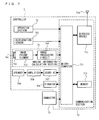
- FIG. 2 is a block diagram illustrating a configuration of the game apparatus body 5.
- the game apparatus body 5 includes a CPU (Central Processing Unit) 10, a system LSI (Large Scale Integration) 11, an external main memory 12, a ROM/RTC (Read Only Memory/Real Time Clock) 13, a disc drive 14, an AV-IC (Audio Video-Integrated Circuit) 15 and the like.
- CPU Central Processing Unit
- LSI Large Scale Integration
- ROM/RTC Read Only Memory/Real Time Clock
- disc drive 14 an AV-IC (Audio Video-Integrated Circuit) 15 and the like.
- AV-IC Audio Video-Integrated Circuit
- the CPU 10 executes the game program stored in the optical disc 4, and then executes the game process.
- the CPU 10 also functions as a game processor.
- the CPU 10 is connected to the system LSI 11.
- the system LSI 11 executes processes such as control of data transfer among respective component parts connected to the systemLSI 11, generation of an image to be displayed, and an acquisition of data from an external apparatus.
- the internal configuration of the system LSI 11 will be described later.
- the external main memory 12 is used as a work area or a buffer area in the CPU 10.
- the ROM/RTC 13 has a ROM (so called a boot ROM) which incorporates a program for booting up the game apparatus body 5 therein, and a clock circuit (a RTC) for counting time.
- the disc drive 14 reads program data, texture data or the like from the optical disc 4, and write the read data into an internal main memory 35 or an external main memory 12 described later.
- an I/O processor 31 To the system LSI 11, provided are an I/O processor 31, a GPU (Graphics Processor Unit) 32, a DSP (Digital Signal Processor) 33, a VRAM (Video RAM) 34, and the internal main memory 35. Although not shown in a diagram, these components parts 31 to 35 are connected to one another via an internal bus.
- the GPU 32 forms a part of a drawing means, and generates an image in accordance with a graphics command given by the CPU 10.
- the VRAM 34 stores data (such as polygon data and texture data) which is necessary to cause the GPU 32 to execute the graphics command.
- the GPU 32 When the image is generated, the GPU 32 generates the image data by using the data stored in the VRAM 34.
- the DSP 33 functions as an audio processor, and generates audio data by using sound data and sound waveform (sound quality) data which are stored in the internal main memory 35 and the external main memory 12.
- the image data and the audio data, which are generated as above described, are read by the AV-IC 15.
- the AV-IC15 outputs the read image data to the monitor 2 via the AV connector 16, and also outputs the read audio data to the speakers 2a embedded in the monitor 2. Accordingly, an image is displayed on the monitor 2, and a sound is outputted from the speakers 2a.
- the I/O processor 31 executes data transmission with components parts which are connected thereto, and also executes downloading of data from an external apparatus.
- the I/O processor 31 is connected to the flash memory 17, a wireless communication module 18, the wireless controller module 19, an extension connector 20, and an external memory card connector 21.
- An antenna 22 is connected to the wireless communication module 18, and
- An antenna 23 is connected to the wireless controller module 19.
- the I/O processor 31 is connected to a network via the wireless communication module 18 and the antenna 22, thereby communicating with other game apparatuses and various servers connected to the network.
- the I/O processor 31 periodically accesses to the flash memory 17 so as to detect data, if any, which is necessary to be transmitted to the network. When the data is detected, the data is transmitted to the network via the wireless communication module 18 and the antenna 22. Further, the I/O processor 31 receives data transmitted from other game apparatuses or data downloaded from a download server via the network, the antenna 22, and the wireless communication module 18, and stores the received data in the flash memory 17.
- the CPU 10 executes the game program so as to read the data stored in the flash memory 17, and to use the data in the game program.
- saved data (result data or intermediate step data) of a game played by using the game apparatus body 5 may be stored, in addition to data transmitted among the game apparatus body 5 and the other game apparatuses or the various servers.
- the I/O processor 31 receives operation data and the like transmitted from the controller 7 via the antenna 23 and the wireless controller module 19, and stores (temporarily stores) the transmitted operation data and the like in the buffer area in the internal main memory 35 and the external main memory 12.
- the internal main memory 35 as with the external main memory 12, a program such as a game program read from the optical disc 4 and a game program read from the flash memory 17, and various data may be stored.
- the internal main memory 35 may also be used as the work area or the buffer area in the CPU 10.
- the extension connector 20 functions as an interface such as an USB or a SCSI, and is capable of communicating with a network, as a substitute for the wireless communication module 19, by connecting with a medium such as an external storage medium, peripheral equipment such as other controllers, or a wired communication connector.
- the external memory card connector 21 allows connection with an external storage medium such as a memory card.
- the I/O processor 31 accesses the external storage medium via the extension connector 20 or the external memory card connector 21, thereby storing and reading data.
- the game apparatus body 5 includes (on a front main surface thereof) a power button 24 of the game apparatus body 5, a game process reset button 25, a slot through which the optical disc 4 is mounted thereon, and an eject button 26 used for dismounting the optical disc 4 through the slot of the game apparatus body 5, and the like.
- the power button 24 and the reset button 25 are connected to the system LSI 11.
- the power button 24 is turned on, the power is supplied to respective component parts of the game apparatus body 5 via an AC adaptor (which is not shown).
- the system LSI 11 reboots a boot-up program of the game apparatus body 5.
- the eject button 26 is connected to the disc drive 14. When the eject button 26 is pressed, the optical disc 4 is dismounted from the disc drive 14.
- FIG. 3 is a perspective view illustrating the controller 7 as viewed from the top rear side thereof.
- FIG. 4 is a perspective view illustrating the controller 7 as viewed from the bottom front side thereof.
- the controller 7 includes a housing 71 formed by plastic molding or the like.
- the housing 71 has a plurality of operation sections 72.
- the housing 71 has a generally parallelepiped shape extending in a longitudinal direction from front to rear. The overall size of the housing 71 is small enough to be held by one hand of an adult or even a child.
- a cross key 72a is provided at the center of the front part of a top surface of the housing 71.
- the cross key 72a is a cross-shaped four-direction push switch.
- the cross key 72a includes operation portions corresponding to the four directions (front, rear, right and left), which are respectively located on cross-shaped projecting portions arranged at intervals of 90 degrees.
- the player selects one of the front, rear, right and left directions by pressing one of the operation portions of the cross key 72a.
- the player can, for example, instruct a direction in which a player character or the like appearing in a virtual game world is to move or select one of a plurality of options.
- the cross key 72a is an operation section for outputting an operation signal in accordance with the above-described direction input operation performed by the player
- an operation section may be provided in another form.
- the cross key 72a may be replaced with an operation section which as four push switches which extend in four directions, respectively, so as to form a cross, and outputs an operation signal in accordance with the player pressing one of the push switches.
- the cross key 72a may be replaced with an operation section having the four push switches in combination with a center switch positioned at the center of the cross of the four push switches.
- the cross key 72a may be replaced with an operation section which includes an inclinable stick (so-called a joy stick) projecting from the top surface of the housing 71 and outputs an operation signal in accordance with the inclining direction of the stick.
- the cross key 72a may be replaced with an operation section which includes a disc-shaped member horizontally slidable and outputs an operation signal in accordance with the sliding direction of the disc-shaped member.
- the cross key 72a may be replaced with a touch pad.
- a plurality of operation buttons 72b, 72c, 72d, 72e, 72f and 72g are provided.
- the operation buttons 72b, 72c, 72d, 72e, 72f and 72g are each an operation section for outputting a respective operation signal assigned to the operation buttons 72b, 72c, 72d, 72e, 72f, or 72g when the player pressed a head thereof.
- the operation buttons 72b, 72c, and 72d are assigned with functions of a first button, a second button, and an A button, for example.
- the operation buttons 72e, 72f and 72g are assigned with functions of a minus button, a home button, a plus button, for example.
- the operation buttons 72a, 72b, 72c, 72d, 72e, 72f and 72g are assigned with various operation functions in accordance with the game program executed by the game apparatus body 5.
- the operation buttons 72b, 72c and 72d are arranged in a line at the center on the top surface of the housing 71 in the front-rear direction.
- the operation buttons 72e, 72f and 72g are arranged in a line in the left-right direction between the operation buttons 72b and 72d on the top surface of the housing 71.
- the operation button 72f has a top surface thereof buried in the top surface of the housing 71, so as not to be inadvertently pressed by the player.
- an operation button 72h is provided in front of the cross key 72a on the top surface of the housing 71.
- the operation button 72h is a power switch for remote-controlling the power of the game apparatus body 5 to be on or off.
- the operation button 72b also has a top surface thereof buried in the top surface of the housing 71, so as not to be inadvertently pressed by the player.
- a plurality of LEDs 702 are provided.
- the controller 7 is assigned with a controller type (number) so as to be distinguishable from the other controllers 7.
- the LEDs 702 are used for informing the player of the controller type which is currently set to controller 7 that he or she is using.
- a signal is transmitted from the wireless controller module 19 to the controller 7 so as to light up one LED, among the plurality of LEDs702, depending on the controller type.
- a sound hole for outputting, to the outside, a sound from a speaker (a speaker 706 shown in FIG. 5 ) described below is provided between the operation button 72b and the operation buttons 72e, 72f, and 72g.
- a recessed portion is formed on a button surface of the housing 71.
- the recessed portion is formed at a position at which an index finger or middle finger of the player is located when the player holds the controller 7 by one hand so as to orient the front surface of the controller 7 toward the markers 8L and 8R.
- an operation button 72i is provided on a slope surface of the recessed portion.
- the operation button 72i is an operation section acting as, for example, a B button.
- the imaging information calculation section 74 is a system for analyzing image data taken by the controller 7 and detecting the position of the center of gravity, the size and the like of an area having a high brightness in the image data.
- the imaging information calculation section 74 has, for example, a maximum sampling period of about 200 frames/sec., and therefore can trace and analyze even a relatively fast motion of the controller 7.
- the imaging information calculation section 74 will be described later in detail.
- the connector 73 is provided on a rear surface of the housing 71.
- the connector 73 is, for example, an edge connector, and is used for engaging and connecting with a connecting cable, for example.
- a coordinate system is defined for the controller 7.
- an X-axis, a Y-axis, and a Z-axis, which are orthogonal to each other, are defined for the controller 7.
- the longitudinal direction of the housing 71 corresponding to the front-rear direction of the controller 7 is defined as the Z-axis direction
- a direction toward the front surface (a surface on which the imaging information calculation section 74 is mounted) of the controller 7 is a Z-axis positive direction.
- the up-down direction of the controller 7 is defined as the Y-axis direction, and a direction toward the top surface (a surface on which the operation button 72a is provided) of the housing 71 is defined as a Y-axis positive direction.
- the left-right direction of the controller 7 is defined as the X-axis direction, and a direction toward the left side surface (a side surface which is not shown in FIG. 3 ) of the housing 71 is defined as an X-axis positive direction.
- FIG. 5 is a perspective view illustrating, as viewed from the top rear surface of the controller 7, a state where an upper casing (a part of the housing 71) of the controller is removed.
- FIG. 6 is a perspective view illustrating, as viewed from the bottom front surface of the controller 7, a state where a lower casing (a part of the housing 71) of the controller 7 is removed.
- FIG. 6 is a perspective view illustrating a reverse side of a substrate 700 shown in FIG. 5 .
- the substrate 700 is fixed inside the housing 71.
- the operation buttons 72a, 72b, 72c, 72d, 72e, 72f, 72g and 72h, an acceleration sensor 701, the LEDs 702, an antenna 754 and the like are provided.
- These elements are connected to a microcomputer 751 (see FIGS. 6 and 7 ) and the like via lines (not shown) formed on the substrate 700 and the like.
- the wireless module 753 (see FIG. 7 ) and the antenna 754 allow the controller 7 to act as a wireless controller.
- the quartz oscillator (not shown), which is provided inside the housing 71, generates a reference clock of the microcomputer 751 described later.
- the acceleration sensor 701 is provided on the substrate 700 to the left of the operation button 72d. That is, the acceleration sensor 701 is provided not at the center portion of the substrate 700 but near the periphery of the substrate 700. Accordingly, the acceleration sensor 701 is capable of detecting a directional change of the gravity acceleration and an acceleration containing a component exerted due to the centrifugal force, in accordance with the controller 7 rotating about the longitudinal direction thereof. Therefore, the game apparatus body 5 and the like can perform a predetermined calculation so as to determine a movement of the controller 7 with sufficient accuracy based on the acceleration data having been detected.
- the imaging information calculation section 74 includes an infrared filter 741, a lens 742, the image pickup element 743, and an image processing circuit 744 located in order, respectively, from the front surface of the controller 7 on the bottom main surface of the substrate 700.
- the connector 72 is attached.
- a sound IC 707 and the microcomputer 751 are provided on a bottommain surface of the substrate 700.
- the sound IC 707 connected to the microcomputer 751 and the amplifier 708 via the line formed on the substrate 700 and the like, outputs a sound signal to the speaker 706 via the amplifier 708 in accordance with the sound data transmitted from the game apparatus body 5.
- a vibrator 704 is attached on the bottom main surface of the substrate 700.
- the vibrator 704 may be, for example, a vibration motor or a solenoid.
- the vibrator 704 connected to the microcomputer 751 via the line formed on the substrate 700 and the like, is powered on/off in accordance with vibration data transmitted from the game apparatus body 5.
- the controller 7 is vibrated by an actuation of the vibrator 704, and the vibration is conveyed to the player's hand holding the controller 7.
- the vibrator 704 is provided near the front part of the housing 71, and therefore a large vibration of the housing 71 allows the player holding the controller 7 to easily feel the vibration.
- FIG. 7 is a block diagram illustrating a configuration of the controller 7.
- the controller 7 includes the communication section 75, in addition to the operation section 72, the imaging information calculation section 74, the acceleration sensor 701, the vibrator 704, the speaker 706, the sound IC 707, and the amplifier 708 as described above.
- the imaging information calculation section 74 includes the infrared filter 741, the lens 742, the image pickup element 743, and the image processing circuit 744.
- the infrared filter 741 allows only infrared light to pass therethrough, among light incident on the front surface of the controller 7.
- the lens 742 collects the infrared light which has passed through the infrared filter 741 and outputs the infrared light to the image pickup element 743.
- the image pickup element 743 is a solid-state image pickup device such as, for example, a CMOS sensor or a CCD.
- the image pickup element takes an image of the infrared light collected by the lens 742.
- the image pickup element 743 takes an image of only the infrared light which has passed through the infrared filter 741 and generates image data.
- the image data generated by the image pickup element 743 is processed by the image processing circuit 744.
- the image processing circuit 744 processes the image data obtained by the image pickup element 743, detects an area thereof having a high brightness, and outputs process result data, which represents the detected position coordinates and size of the area, to the communication section 75.
- the imaging information calculation section 74 is fixed to the housing 71 of the controller 7. The imaging direction of the imaging information calculation section 74 can be changed by changing the direction of the housing 71.
- the controller 7 preferably includes a three-axial (X-axis, Y-axis, and Z-axis) acceleration sensor 701.
- the three-axial acceleration sensor 701 detects a linear acceleration in three directions, that is, the up-down direction (Y-axis shown in FIG. 3 ), the left-right direction (X-axis shown in FIG. 3 ), and the front-rear direction (Z-axis shown in FIG. 3 ).
- an acceleration detection means for detecting a linear acceleration along at least two axial directions may be used depending on a type of a control signal used for a game process.
- the acceleration sensor 701 as described above may be of the type available fromAnalog Devices, Inc.
- the acceleration sensor 701 is an electrostatic capacitance (capacitance-coupling) type that is based on silicon micro-machined MEMS (Micro Electro Mechanical Systems) technology.
- electrostatic capacitance capacitance-coupling
- MEMS Micro Electro Mechanical Systems
- any other suitable technology of acceleration detection means for example, piezoelectric type or piezoresistance type
- any other suitable technology of acceleration detection means for example, piezoelectric type or piezoresistance type
- An acceleration detection means as used in the acceleration sensor 701, is only capable of detecting an acceleration (linear acceleration) along a straight line corresponding to each axis of the acceleration sensor 701.
- the direct output of the acceleration sensor 701 is limited to signals indicative of the linear acceleration (static or dynamic) along each of the three axes thereof.
- the acceleration sensor 701 cannot directly detect movement along a non-linear (e.g. arcuate) path, rotation, rotational movement, angular displacement, tilt, position, attitude, or any other physical characteristic.
- a computer such as a processor (for example, the CPU 10) of the game apparatus or a processor (for example, the microcomputer 751) of the controller, processes acceleration signals outputted from the acceleration sensor 701
- a processor for example, the CPU 10
- a processor for example, the microcomputer 751
- additional information relating to the controller 7 can be inferred or calculated (determined), as one skilled in the art will readily understand form the description herein.
- the computer will process the acceleration signal outputted from the acceleration sensor 701 of the controller 7 which is in a static state (that is, a case where it is anticipated that an acceleration detected by the acceleration sensor 701 will include only a gravity acceleration) will be described.
- the controller 7 is actually in the static state, it is possible to determine whether or not the controller 7 tilts relative to the gravity direction and to also determine a degree of the tilt, based on the acceleration having been detected.
- the controller 7 tilts relative to the vertically downward direction, based on only whether or not 1G (gravity acceleration) is applied in the direction of the detection axis of the acceleration sensor 701. Further, it is possible to determine a degree to which the controller 7 tilts relative to the vertically downward direction, based on a magnitude of the acceleration applied in the direction of the detection axis. Further, in the case of the acceleration sensor 701 capable of detecting an acceleration in multi-axial directions, the acceleration signals having been detected in the respective axes are processed so as to more specifically determine the degree to which the controller 7 tilts relative to the gravity direction.
- 1G gravitation acceleration
- the processor may calculate, based on the output from the acceleration sensor 701, data representing an angle at which the controller 7 tilts, an approximate degree to which the controller 7 tilts may be inferred based on the output form the acceleration sensor 701 without calculating the data representing the angle of the tilt.
- the acceleration sensor 701 is used in combination with the processor, the tilt, attitude, or position of the controller 7 can be determined.
- the acceleration sensor 701 detects an acceleration based on a movement of the acceleration sensor 701, in addition to the gravity acceleration component. Therefore, when the gravity acceleration component is eliminated through a predetermined process, it is possible to determine, for example, a direction in which the controller 7 moves. Specifically, when the controller 7 including the acceleration sensor 701 is dynamically accelerated and moved with a hand of a player, it is possible to calculate various movements and/or positions of the controller 7 by processing the acceleration signals generated by the acceleration sensor 701. Even when it is anticipated that the acceleration sensor 701 will be in the dynamic state, the acceleration based on the movement of the acceleration sensor 701 is eliminated through a predetermined process, whereby it is possible to determine the tilt of the controller 7 relative to the gravity direction.
- the acceleration sensor 701 may include an embedded signal processor or another type of dedicated processor for performing any desired processing of the acceleration signals outputted by an embedded acceleration detection means prior to outputting signals to the microcomputer 751.
- the acceleration sensor 701 is intended to detect static acceleration (for example, gravity acceleration)
- the embedded or dedicated processor could convert the detected acceleration signal to a corresponding tilt angle (or another preferable parameter).
- Data representing the respective acceleration detected by the acceleration sensor 701 is outputted to the communication section 75.
- the communication section 75 includes, the microcomputer 751, a memory 752, the wireless module 753, and the antenna 754.
- the microcomputer 751 controls the wireless module 753 for wirelessly transmitting the transmission data while using the memory 752 as a storage area during the process.
- the microcomputer 751 controls operations of the sound IC 707 and the vibrator 704, based on the data received from the game apparatus body 5 by the wireless module 753 via the antenna 754.
- the sound IC 707 processes the sound data and the like transmitted from the game apparatus body via the communication section 75.
- the microcomputer 751 actuates the vibrator based on, for example, the vibration data (for example, a signal for powering the vibrator 704 ON/OFF) transmitted by the game apparatus body 5 via the communication section 75.
- Data from the controller 7 including an operation signal (key data) from the operation section 72, three-axial direction acceleration signals (X, Z, and Z axes direction acceleration data) from the acceleration sensor 701, and the process result data from the imaging information calculation section 74 are outputted to the microcomputer 751.
- the microcomputer 751 temporarily stores, in the memory 752, the respective data (key data, X, Y, and X axes direction acceleration data and process result data) as the transmission data which is to be transmitted to the wireless controller module 19.
- the wireless transmission from the communication section 75 to the wireless controller module 19 is performed periodically at a predetermined time interval. Since a game process is generally performed at a cycle of 1/60 sec., the wireless transmission needs to be performed at a cycle of a shorter time period.
- the game process unit is 16. 7ms (1/60 sec.), and the transmission interval of the communication section 75 structured using the Bluetooth (registered trademark) technology is 5ms.
- the microcomputer 751 outputs the transmission data stored in the memory 752 as a series of operation information to the wireless module 753.
- the wireless module 753 uses, for example, the Bluetooth (registered trademark) technology to transmit the operation information representing an electric wave signal from the antenna 754 as a carrier wave signal of a predetermined frequency.
- the key data from the operation section 72 included in the controller 7, the X, Y, and Z axes direction acceleration data from the acceleration sensor 701 and process result data from the imaging information calculation section 74 are transmitted from the controller 7.
- the wireless controller module 19 of the game apparatus body 5 receives the electric wave signal, and the game apparatus body 5 demodulates or decodes the electric wave signal to obtain the series of the operation signal information (the key data, the X, Y, and Z axes direction acceleration data, and the process result data). Based on the obtained operation information and the game program, the CPU 10 of the game apparatus body 5 performs the game process.
- the communication section 75 is structured using the Bluetooth (registered trademark) technology, the communication section 75 can also have a function of receiving transmission data which is wirelessly transmitted from other devices.
- the overall size of the controller 7 is small enough to be held by one hand of an adult or even a child.
- a player holds the controller 7 by one hand and waves the controller 7.
- FIG. 8 shows that the player is holding the controller 7 and waving the controller 7 up and down or left and right.
- the game apparatus body 5 analyzes an elapsed time after determination, made by the game apparatus body 5, of a moving direction or a redirected direction (hereinafter, simply referred to as the moving direction) of the controller 7, and the like.
- the moving direction and the elapsed time are used to perform a game process.
- the operation information (specifically, the X, Y, and Z axes direction acceleration data) representing an attitude of the controller 7 in a static state is provided to the game apparatus body 5.
- the operation information representing a dynamic state is provided from the controller 7 to the game apparatus body 5 in accordance with an acceleration and the centrifugal force applied at the time of accelerating in the moving direction, and an acceleration and the centrifugal force applied at the time of decelerating so as to stop the movement.
- the change in acceleration applied to the controller 7 can be detected by the acceleration sensor 701, and therefore when the X, Y, and Z axes direction acceleration data outputted by the acceleration sensor 701 is processed additionally, the attitude of the controller 7 in the static state and the moving direction of the controller 7 in the dynamic state can be calculated. Further, an additional process is performed by using two-axial (for example, the X and Y axes) direction acceleration data which is outputted by the acceleration sensor 701, whereby the attitude of the controller 7 in the static state and the moving direction of the controller 7 in the dynamic state relative to the two-dimensional direction can be calculated.
- two-axial (for example, the X and Y axes) direction acceleration data which is outputted by the acceleration sensor 701, whereby the attitude of the controller 7 in the static state and the moving direction of the controller 7 in the dynamic state relative to the two-dimensional direction can be calculated.
- the acceleration sensor 701 outputs acceleration data indicative of an acceleration in precisely the opposite direction to the acceleration applied to the acceleration sensor 701 (that is, an actually accelerating direction or decelerating direction). That is, the acceleration sensor 701 outputs the acceleration data depending on an inertial force arising from the acceleration of the acceleration sensor 701. Further, the gravity acceleration, which is applied to the acceleration sensor 701 when the controller 7 is in a static state, is outputted as acceleration data in the same direction as the gravity direction.
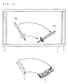
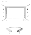
- FIGS. 9 to 13 are diagrams each illustrating an example of a game process or an information process performed in accordance with the above-described moving direction.
- a process of moving an object displayed on the monitor 2 in accordance with the above-described moving direction for example, changing a direction for receiving a volleyball in a virtual game space displayed in the monitor 2, swinging a sword in the virtual game space displayed in the monitor 2, cutting a substance situated in the virtual game space, moving a substance situated in the virtual game space or the like
- a sound is caused to be outputted from the speakers 2a provided to the monitor 2 or the speaker 706 provided to the controller 7 in accordance with the moving direction.
- a gesture of a browser displayed on a display screen such as moving a window, closing a window, page scrolling, and the like
- an arm object OBJ of a volleyball player character situated in a virtual game space is displayed.
- the player holds the controller 7 by two hands and controls the controller 7 as if the player receives a volleyball.
- a direction of the arms of the arm object OBJ is also changed, in the virtual game space, in the direction corresponding to the changeddirection of the controller 7 (the moving direction) .
- the player changes the direction of the controller 7 from left to right.
- the direction of the arms of the arm object OBJ changes from left to right, and the arm object OBJ receives the ball object B.
- a sword object OBJ situated in a virtual game space is displayed on the monitor 2.
- the sword object OBJ is swung, in the virtual game space, in the direction corresponding to the moving direction of the controller 7.
- FIG. 11A a log object OBJ situated in a virtual game space is displayed on the monitor 2.
- the log object OBJ is cut, in the virtual game space, along a direction corresponding to the moving direction of the controller 7, and divided and separated into log objects OBJ1 and OBJ2.
- an object for cutting the target materials for example, a cutting tool object such as a sword, a knife and an ax
- a trail of the object for cutting the target materials may be displayed, or only a change in a movement of the target materials may be displayed.
- a window W used by a browser or the like is displayed on the monitor 2.
- the window W moves, in the display screen, to a direction corresponding to the moving direction of the controller 7.
- the elapsed time from the recognition of the moving direction can be used as a degree of reliability of the moving direction having been determined.
- the game process, the information processing or the like can be performed by using the moving direction having been determined.
- the game process, the information processing or the like can be performed by using the moving direction having been determined.
- the moving direction can be determined even if the controller 7 is waved weakly such that the direction of the controller 7 is changed slowly. Therefore, even in the case where the player holds the controller 7 by two hands and changes the direction of the controller 7, the moving direction of the controller 7 can be determined. Further, even in the case where the controller is waved by a child or an adult female who cannot wave the controller 7 vigorously, the moving direction can be determined accurately.
- FIG. 14 is a diagram illustrating main data to be stored in the external main memory 12 and/or the internal main memory 35 (hereinafter, collectively referred to as a main memory) of the game apparatus body 5.
- the main memory stores acceleration data Da, gravity component vector data Db, gravity component eliminated vector data Dc, acceleration magnitude data Dd in respective directions, deceleration magnitude data De in respective directions, deceleration vector data Df, moving direction vectordata Dg, recognition elapsed time data Dh, maximum speed record data Di, attitude data Dj, image data Dk and the like.
- the main memory also stores data necessary for the game process such as data relating to the object OBJ and other objects appearing in a game (positional data and the like) or data relating to a virtual game space (background data and the like), in addition to data included in the information shown FIG. 14 .
- the acceleration data Da represents an acceleration applied to the controller 7, and stores acceleration data included in the series of operation information transmitted by the controller 7 as the transmission data.
- the acceleration data Da includes X-axis direction acceleration data Da1 representing an acceleration component rX which is detected along an X-axis component by the acceleration sensor 701, and Y-axis direction acceleration data Da2 representing an acceleration component rY which is detected along a Y-axis component by the acceleration sensor 701.
- the wireless controller module 19 included in the game apparatus body 5 receives acceleration data contained in the operation information transmitted from the controller 7 at predetermined intervals (for example, every 1/200sec.), and stores the acceleration data in a buffer (not shown) of the wireless controller module 19. Thereafter, most recent acceleration data stored in the buffer is read for each frame (for example, every 1/60sec.) corresponding to a game process cycle so as to update the acceleration data Da in the main memory.
- the above-described operation information includes the acceleration data which is detected along a Z-axis component by the acceleration sensor 701.
- the acceleration data Da will not include Z-axis direction acceleration data representing an acceleration component rZ which is detected along the Z-axis component by the acceleration sensor 701.
- the acceleration data Da may be updated in another process cycle.
- the acceleration data Da may be updated for every transmission cycle of the controller 7, and the updated acceleration data may be used for every game process cycle.
- a cycle in which acceleration data Da1 and Da2 are stored in the acceleration data Da is different from the game process cycle.
- the gravity component vector data Db stores vector data representing an acceleration of a gravity component applied to the controller 7 (a gravity component vector). Specifically, the gravity component vector data Db stores data respectively representing an X-axis direction component gX and a Y-axis direction component gY of the gravity component vector.
- the gravity component eliminated vector data Dc stores vector data (gravity component eliminated vector) representing an acceleration applied to the controller from which the gravity component applied to the controller 7 has been eliminated. Specifically, the gravity component eliminated vector data Dc stores an X-axis direction component accX and a Y-axis direction component accY of the gravity component eliminated vector.
- the acceleration magnitude data Dd for the respective directions stores data representing a magnitude of an acceleration applied to the controller 7 when the controller 7 is moved in a real space.
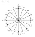
- N directions (0th to N-1th directions) are set on an X, Y-axes plane, and an acceleration magnitude p(n) is calculated for each of the N directions (N-th direction).
- Data representing the acceleration magnitude p(n) calculated with respect to each of the 0th to N-1th directions is stored in acceleration magnitude data Dd (0) for the 0th direction to acceleration magnitude data Dd (N-1) for the N-1th direction, respectively, which are collectively included in the acceleration magnitude data Dd.
- the deceleration magnitude data De for the respective directions stores data representing a magnitude of a deceleration applied to the controller 7 when the controller 7 is moved in the real space.
- the above-described 0th to N-1th directions are set, and a deceleration magnitude m (n) is calculated for each of the N directions (N-th direction).
- Data representing the deceleration magnitude m(n) calculated for each of the 0th to N-1th directions is stored in deceleration magnitude data De (0) for the 0th direction to deceleration magnitude data De (N-1) for the N-1th direction, respectively, which are collectively included in the deceleration magnitude data De.
- the deceleration vector data Df stores vector (deceleration vector) data representing a direction in which the controller 7 is decelerating and a magnitude of the deceleration thereof in the real space. Specifically, the deceleration vector data Df stores data representing an X-axis direction component sumX and a Y-axis direction component sumY of the deceleration vector.
- the moving direction vector data Dg stores data representing a moving direction dir in which the controller is being moved. Specifically, the moving direction vector data Dg stores data representing the moving direction dir by a two-dimensional vector having a magnitude of 1.
- the recognition elapsed time data Dh stores a recognition elapsed time c after the moving direction dir having been calculated.
- the maximum speed record data Di stores data representing a maximum value of a deceleration vector magnitude in a series of processes (a maximum speed record Sp_max).
- the attitude data Dj stores data representing an attitude direction pos of the controller 7 in a static state. Specifically, a direction of the gravity acceleration applied on the X, Y-axes plane is regarded as the attitude direction pos, and the attitude data Dj stores data representing the attitude direction pos in a form of a two-dimensional vector having a magnitude of 1.
- the image data Dk includes object image data Dkl and the like.
- the object image data Dk1 generates a game image by locating an object OBJ in a virtual game space.
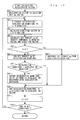
- FIG. 15 is a flowchart illustrating a flow of the game process executed by the game apparatus body 5.
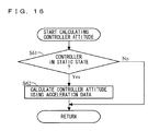
- FIG. 16 shows a sub-routine illustrating in detail a process of calculating the attitude of the controller in step 44 shown in FIG.15 .
- FIG. 17 shows a sub-routine illustrating in detail a process of calculating the deceleration vector in step 47 shown in FIG. 15 .
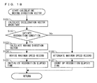
- FIG. 18 shows a sub-routine illustrating in detail a process of calculating the moving direction vector in step 48 shown in FIG. 15 .
- FIGs. 16 shows a sub-routine illustrating in detail a process of calculating the attitude of the controller in step 44 shown in FIG.15 .
- FIG. 17 shows a sub-routine illustrating in detail a process of calculating the deceleration vector in step 47 shown in FIG. 15 .
- FIG. 18 shows a sub-routine illustrating in detail a process of calculating the moving direction vector in step 48 shown in FIG. 15 .
- FIGS. 15 to 18 show the game process to be performed after completion of the above-described processes.
- the CPU 10 initializes the game process (step 41), and proceeds to the next step.
- initialization of the game process in above-described step 41 for example, in the case of a game process in which a direction of an arm of a game character is to be changed or a substance is to be moved in a virtual game space, initialization relating to setting of the virtual game space, location of game objects and the like are performed.
- the CPU 10 initializes a recognition process (step 42), and proceeds to the next step.
- respective parameters for calculating the moving direction of the controller 7 are initialized.
- the CPU 10 sets the X-axis direction component gX and the Y-axis direction component gY of the gravity component vector stored in the gravity component vector data Db to 0, respectively.
- the CPU 10 sets the X-axis direction component accX and the Y-axis direction component accY of the gravity component eliminated vector stored in the gravity component eliminated vector data Dc to 0, respectively.
- the CPU 10 sets the acceleration magnitude p (n) to 0, the acceleration magnitude p (n) being stored in each of the acceleration magnitude data Dd0 in the 0th direction to the acceleration magnitude data Dd (N-1) in the N-1th direction.
- the CPU 10 sets the deceleration magnitude m(n) to 0, the deceleration magnitude m(n) being stored in each of the deceleration magnitude data De0 for the 0th direction to the deceleration magnitude data De (N-1) for the N-1th direction.
- the CPU 10 sets the X-axis direction component sumX and the Y-axis direction component sumY of the deceleration vector stored in the deceleration vector data Df to 0, respectively.
- the CPU 10 sets each of the moving direction dir and the attitude direction pos, which are stored in the moving direction vector data Dg and the attitude data Dj, respectively, to a two-dimensional vector which has a length of 1 and is oriented in a predetermined direction.
- the CPU 10 sets the maximum speed record Sp_max stored in the maximum speed record data Di to 0.
- the CPU 10 then sets the recognition elapsed time c stored in the recognition elapsed time data Dh to 0.
- the CPU 10 obtains the acceleration component rX and the acceleration component rY (step 43) and proceeds to the next step.
- the CPU 10 stores an acceleration, which is represented by the acceleration data included in most recent operation information received from the controller 7, as the acceleration component rX and the acceleration component rY in the acceleration data Da.
- the acceleration represented by the X-axis direction acceleration data included in the most recent operation information received from the controller 7 is stored in the X-axis direction acceleration data Da1 as the acceleration component rX.
- the acceleration represented by the Y-axis direction acceleration data included in the most recent operation information is stored in the Y-axis direction acceleration data Da2 as the acceleration component rY.
- the CPU 10 calculates the attitude of the controller 7 (step 44), and then proceeds to the next step.
- the attitude calculation process relating to the controller 7, which is performed in above-described step 44, will be described.
- the CPU 10 determines whether or not the controller 7 is in a static state or not, with reference to the acceleration component rX and the acceleration component rY stored in the acceleration data Da (step 61). As an example, the CPU 10 determines that the controller 7 is not in the static state in the case where a value of either of the acceleration component rX and the acceleration component rY is equal to or more than a value corresponding to the gravity acceleration. As another example, in the case where variation in each of the acceleration component rX and the acceleration component rY is smaller than a predetermined value, the controller 7 is determined to be in the static state.
- step 61 for determining the state of the controller 7.
- the CPU 10 proceeds to next step 62 in the case where the controller 7 is in the static state.
- the CPU 10 ends the process of the sub-routine in the case where the controller 7 is not in the static state.
- step 62 the CPU 10 calculates the attitude direction pos by using the acceleration component rX and the acceleration component rY, stores the calculated attitude direction pos in the attitude data Dj, and then ends the process of the sub-routine.
- the gravity acceleration is applied to the controller 7.
- the attitude direction pos is in the X-axis positive direction.
- the controller 7 is left at rest while the front surface of the controller 7 is facing upward or downward, that is, the controller 7 is left at rest vertically, and thus the attitude direction pos is either in the Z-axis positive direction or in the Z-axis negative direction.
- the CPU 10 stores the three-dimensional attitude direction pos, which represents the direction of the gravity acceleration applied to the controller 7, in the attitude data Dj.
- the CPU 10 calculates the gravity component applied to the controller 7 (step 45), and proceeds to the next step.
- the CPU 10 refers to the acceleration component rX and the acceleration component rY which are stored in the acceleration data Da, and X-axis direction component gX and Y-axis direction component gY of the gravity component vector which are stored in the gravity component vector data Db.
- the CPU 10 then calculates a new X-axis direction component gX and a new Y-axis direction component gY, respectively, as follows, and then updates the gravity component vector data Db.
- the gravity component vector (gX, gY) is a parameter representing the gravity component applied to the controller 7.
- the CPU 10 calculates an acceleration component from which the gravity component has been eliminated (the gravity component eliminated vector) (step 46), and proceeds to the next step.
- the CPU 10 refers to the acceleration component rX and the acceleration component rY each stored in the acceleration data Da, and the X-axis direction component gX and the Y-axis direction component gY of the gravity component vector each stored in the gravity component vector data Db.
- the CPU 10 calculates an X-axis direction component accX and a Y-axis direction component accY of a new gravity component eliminated vector in accordance with equations as indicated below, and updates the gravity component eliminated vector data Dc.
- the gravity component eliminated vector (accX, accY) is an acceleration component which is obtained by eliminating the gravity component (that is, the gravity component vector (gX, gY)) from the acceleration component rX and acceleration component rY which are applied to the controller 7, and also corresponds to a parameter indicating an acceleration component exerted when a player moves the controller 7.
- step 47 the CPU 10 calculates the deceleration vector (step 47), and proceeds to the next step.
- the CPU 10 calculates the deceleration vector (step 47), and proceeds to the next step.
- FIG. 17 a process of calculating the deceleration vector performed in above-described step 47 will be described.
- the CPU 10 performs initialization in the process of calculating the deceleration vector (step 81), and proceeds to the next step. For example, the CPU 10 initializes a loop counter n to 0. The CPU 10 also sets the X-axis direction component sumX and the Y-axis direction component sumY, which are each stored in the deceleration vector data Df, to 0, respectively.
- N directions which are different from one another, are arranged at intervals of a uniform angle on the X, Y-axes plane for determining the moving direction dir.
- the CPU 10 calculates a new acceleration magnitude p (n) and a new deceleration magnitude m(n) in the n-th direction based on equations as indicated below, and updates the acceleration magnitude data Dd (n) and the deceleration magnitude data De (n) with respect to the n-th direction.
- the CPU 10 calculates a direction vector having a length of 1 which represents the n-th direction (step 83), and proceeds to the next step.
- An X-axis component vecX and a Y-axis component vecY of the direction vector which represent the n-th direction are respectively calculated based on equations as indicated below.
- the CPU 10 calculates a dot product dp of the gravity component eliminated vector (accX, accY) and the direction vector (vecX,vecY) (step 84), and proceeds to the next step.
- the CPU 10 determines whether or not the dot product dp is a negative value (step 85).
- the dot product dp which has been calculated in above-described step 84, indicates the n-th direction component of the gravity component eliminated vector (accX, accY).
- the acceleration data outputted by the acceleration sensor 701 represents an acceleration in a direction precisely opposite to an acceleration applied in accordance with the movement of the controller 7 (i.e., a direction in which the controller 7 is actually accelerating or decelerating).
- a negative acceleration is applied in the n-th direction (for example, the controller is moving in the n-th direction at a decelerated rate, or moving in a direction opposite to the n-th direction at an accelerated rate) .
- a positive acceleration is applied in the n-th direction (for example, the controller is moving in the n-th direction at an accelerated rate, or moving to a direction opposite to the n-th direction at a decelerated rate).
- the CPU 10 proceeds to the next step 90.
- the CPU 10 proceeds to next step 86.
- step 86 the CPU 10 adds the dot product dp to the deceleration magnitude m(n) in the n-th direction, and proceeds to the next step. Specifically, the CPU 10 calculates a new deceleration magnitude m(n) in the n-th direction as follows, and updates the deceleration magnitude data De (n) with respect to the n-th direction. m n ⁇ m n + dp
- the CPU 10 determines whether or not the deceleration magnitude m(n) in the n-th direction is larger than the acceleration magnitude p (n) in the n-th direction (step 87). In the case of m(n)>p(n), the CPU 10 changes the deceleration magnitude m(n) so as to equalize the deceleration magnitude m(n) with the acceleration magnitude p(n) (step 88), and proceeds to next step 90. Specifically, in step 88, the CPU 10 sets as follows. m n ⁇ p n The CPU 10 then updates the deceleration magnitude data De (n) in the n-th direction.
- step 88 the deceleration magnitude m(n) in the n-th direction is restricted so as not to exceed the acceleration magnitude p (n) in the n-th direction, and therefore, the deceleration magnitude m(n) is added in the case where acceleration is applied immediately before deceleration. That is, acceleration and deceleration in a given direction of the controller 7 is processed as a set.
- step 85 in the case where it is determined that the controller 7 is accelerating in the n-th direction, the CPU 10 subtracts the dot product dp from the acceleration magnitude p(n) in the n-th direction (step 89), and proceeds to next step 90. Specifically, the CPU 10 calculates a new acceleration magnitude p (n) in the n-th direction as follows, and updates the acceleration magnitude data Dd(n) with respect to the n-th direction. p n ⁇ p n - dp
- the dot product dp represents a negative value. Therefore, to the acceleration magnitude p(n), an absolute value of the dot product dp is added, in the event.
- step 90 the CPU 10 adds the deceleration magnitude m (n) in the n-th direction to the deceleration vector, and proceeds to the next step.
- the CPU 10 refers to the X-axis direction component sumX and the Y-axis direction component sumY of the deceleration vector each stored in the deceleration vector data Df.
- the CPU 10 calculates a new X-axis direction component sumX and a new Y-axis direction component sumY, respectively, based on equation indicated as below, and updates the deceleration vector data Df.
- step 48 the CPU calculates the moving direction vector (step 48), and proceeds to the next step.
- the CPU calculates the moving direction vector (step 48), and proceeds to the next step.
- the calculation of the moving direction vector performed in above-described in step 48 will be described.
- the CPU 10 calculates a a deceleration vector magnitude Sp (step 101), and proceeds to the next step.
- the CPU 10 refers to the X-axis direction component sumX and the Y-axis direction component sumY each stored in the deceleration vector data Df, and calculates the deceleration vector magnitude Sp based on equation 1.
- Sp sumX 2 + sumY 2
- the CPU 10 determines whether or not the calculated deceleration vector magnitude Sp satisfies a recognition condition for recognizing the moving direction (step 102). For example, in the case where the deceleration vector magnitude Sp calculated in above-described step 101 is larger than the maximum speed record Sp max described later, and in the case where the magnitude Sp is equal to or larger than a predetermined value, the same deceleration vector magnitude Sp is determined to satisfy the recognition condition.
- the above-described predetermined value is a minimum deceleration vector magnitude necessary to recognize the moving direction dir, and is set to 0.5, for example.
- the CPU 10 proceeds to next step 103.
- the CPU 10 proceeds to next step 106.
- step 103 the CPU 10 calculates a current direction of the deceleration vector as the moving direction dir, and proceeds to the next step. For example, the CPU 10 calculates a two-dimensional vector having a length of 1, which is obtained by normalizing the deceleration vector (sumX, sumY), stored in current deceleration vector data Df, and updates the moving direction vector data Dg by setting the two-dimensional vector as the moving direction dir.
- the CPU 10 updates the maximum speed record data Di by setting the deceleration vector magnitude Sp, which has been calculated in above-described step 101, as the maximum speed record Sp_max (step 104).
- the CPU 10 initializes the recognition elapsed time c to 0, updates the recognition elapsed time data Dh (step 105), and ends the process of the sub-routine.
- the CPU 10 attenuates the maximum speed record Sp_max by a predetermined amount, updates the maximum speed record data Di (step 106), and then proceeds to the next step. For example, with reference to the maximum speed record Sp_max stored in current maximum speed record data Di, the CPU 10 calculates a new maximum speed record Sp_max by multiplying the maximum speed record Sp_max by a predetermined attenuation coefficient (which is a positive value smaller than 1, and is, for example, 0.98) thereby updating the maximum speed record data Di.
- a predetermined attenuation coefficient which is a positive value smaller than 1, and is, for example, 0.98
- the CPU 10 counts the recognition elapsed time c (step 107), and ends the process of the sub-routine. For example, the CPU 10 adds 1 to the recognition elapsed time c stored in the recognition elapsed time data Dh, thereby updating the recognition elapsed time c. That is, the recognition elapsed time c is such parameter that is initialized to 0 when the moving direction dir is calculated in above-described step 105, and is updated when the determination condition is not satisfied.
- the CPU 10 executes a game main process (step 49), and then proceeds to the next step.
- the CPU 10 is capable of executing the game main process by using the moving direction dir, the recognition elapsed time c and the attitude direction pos, respectively calculated in the processes of above-described steps 41 to 48.
- an object is moved in a virtual game space (for example, a direction of an arm of an object character is changed, a sword is swung, a substance is moved or the like) in accordance with the moving direction dir, or a sound is generated from the speakers 2a or the speaker 706 included in the controller 7 in accordance with the moving direction dir.
- the CPU 10 determines whether or not to end a game (step 50). For example, as a condition for ending the game, a case where a condition for game over is satisfied, a case where a player has performed an operation for ending the game or the like is considered.
- the CPU 10 returns to above-described step 43 so as to repeat the process in the case where the game is not ended.
- the CPU 10 ends the process of the flowchart in the case where the game is ended.
- acceleration data process As shown in FIG. 20 , in the case where the controller 7 is moved in the X-axis positive direction from a static state, and then stilled again, an acceleration along the X-axis positive direction is applied (an accelerated state) to the controller 7, and then an acceleration along the X-axis negative direction is applied (a decelerated state) to the controller 7.
- the acceleration sensor 701 embedded in the controller 7 outputs acceleration data precisely opposite to the acceleration applied to the acceleration sensor 701.
- the acceleration sensor 701 outputs acceleration data representing the acceleration along the X-axis negative direction, and then outputs acceleration data representing the acceleration along the X-axis positive direction.
- the gravity acceleration is applied constantly to the controller 7. However, the gravity acceleration will be omitted for the sake of simple description.
- the moving direction dir is determined by focusing the acceleration along the X-axis positive direction only, it is difficult to distinguish the acceleration along the X-axis positive direction from the deceleration which is applied after the controller 7 is moved and accelerated to the X-axis negative direction. Therefore, it is difficult to improve a detection accuracy of the moving direction dir.
- the above-described embodiment not only the above-described acceleration, but also the deceleration applied immediately after the acceleration is considered in a combined manner, whereby the deceleration is specified, and the moving direction dir is recognized.
- positive variables are set by accumulating a magnitude of a positive acceleration and a magnitude of a negative acceleration, respectively, which are applied in a predetermined direction, and the positive variables are each attenuated at a predetermined rate.
- the both variables are controlled such that one of the variables will not exceed another of the variables so as to consider an acceleration and a deceleration applied immediately thereafter as a set, whereby the one of the variables is specified as such that represents the deceleration. It may be assumed that the larger the variable of the deceleration in a predetermined direction is, the higher the possibility that the controller 7 has been waved to the predetermined direction is.
- Determination focusing on the deceleration is performed with respect to a plurality of directions (16 directions in the present embodiment, as shown in FIG. 19 ), and the determination is summed, whereby a deceleration vector at the time point is calculated.
- a deceleration vector along the X-axis positive direction is calculated, whereby the moving direction dir in the X-axis positive direction is determined.
- the moving direction dir is recognized by focusing on the deceleration applied immediately after the acceleration, whereby distinction between the acceleration and the deceleration can be performed accurately. Accordingly, the detection accuracy of the moving direction dir can be improved. Therefore, the above-described moving direction dir can be recognized even in the case where the controller is waved weakly such as the case where the direction of the controller 7 is changed slowly.
- the deceleration vector is a virtual two-dimensional vector, which is constantly attenuated (see step 82), and the deceleration vector magnitude Sp is increased by accumulating the deceleration magnitude m(n) (see step 90).
- the deceleration vector magnitude Sp reaches a predetermined value or more, a direction of the deceleration vector is recognized as the moving direction dir. That is, since the deceleration vector is constantly attenuated, it is necessary to continuously accumulate an acceleration of a deceleration applied in a single direction so as to keep the deceleration vector magnitude Sp equal to or more than the above-described predetermined value.
- the accumulated value is obtained from the acceleration data outputted by the acceleration sensor 701, and thus when the acceleration of the deceleration detected by the acceleration sensor 701 continues in a uniform trend, the moving direction dir is recognized.
- the acceleration sensor 701 that is, the controller 7
- the acceleration sensor 701 that is, the controller 7
- the recognition condition is set. For example, when the maximum speed record Sp_max is initialized to an extremely small value immediately after the moving direction dir is calculated, a small movement of the controller 7 performed after calculating the moving direction dir is recognized, and thus possibility of mis recognition will increase.
- the maximum speed record Sp_max is multiplied by a positive value, which is close to and smaller than 1 (e.g., 0.98), as an attenuation rate, and thus it is possible to recognize a subsequent movement of the controller 7 without frequently recognizing the unstable movement as described above. Accordingly, it is possible to recognize the moving direction accurately and stably.
- the parameters obtained in the above-described acceleration data process can be used in various manners.
- the moving direction dir it is possible to estimate to which direction a player moves the controller 7, relative to the coordinate axes defined for the controller 7 (see FIGS. 3 and 4 ) .
- the moving direction dir it is possible to infer in which direction, relative to a body of the controller 7, the controller 7 is moved (for example, a top surface direction or a front surface direction of the controller 7). In this manner, the moving direction relative to the body of the controller 7 can be used for the game main process.
- the game main process can be performed based on a degree of reliability of the calculated moving direction dir.
- the recognition elapsed time c is a parameter which is initialized to 0 when a new moving direction dir is calculated. That is, the recognition elapsed time c is initialized each time a direction in which a player waves the controller 7 changes. Generally, when the player waves the controller 7 to a first direction, the player tends to move the controller 7 to the direction opposite to the first direction immediately before the player waves the controller 7 to the first direction (a so-called taking-back action).
- the moving direction dir representing the direction opposite to the above-described first direction is calculated during the taking-back action being performed, and then the moving direction dir representing the above-described first direction is calculated.
- the main game process can be performed by using the moving direction dir which is calculated when the recognition elapsed time c reaches a given count or more.
- the moving direction dir and the attitude direction pos when used, it is possible to infer a direction in which the player is moving the controller 7 in a real space in which a player is operating the controller 7.
- the moving direction dir when used, it is possible to infer the direction in which the controller 7 is waved, relative to the body of the controller 7.
- the attitude direction pos represents a direction of the gravity acceleration applied to the controller 7 at the time point prior to the player moving the controller 7 or the like, and also represents data indicating the vertically downward direction in the real space relative to the body of the controller 7.
- the moving direction dir and the attitude direction pos it is possible to infer the direction in which the controller 7 is waved in the real space (for example, a horizontal direction, up-down direction and the like in the real space).
- a basic attitude or a direction for operating the controller 7 is set (forexample, directing the front surface of the controller 7 to the monitor 2, or directing one side surface of the controller 7 to the monitor 2 while the controller 7 being held transversely, such that the controller 7 points to the monitor 2)
- the direction such as an up-down direction, a right-left direction and a front-rear direction, in which the player wave the controller 7.
- the game main process can be performed based on the degree of the reliability of the moving direction dir as with the above-described case.
- attitude direction pos may be replaced with the gravity component vector (gX, gY).
- the gravity component vector (gX, gY) is a parameter representing an acceleration component constantly applied to the controller 7, among the acceleration components rX and rY which are applied to the controller 7.
- the gravity component vector (gX, gY) can be used as a direction of the gravity acceleration applied to the controller 7.
- the attitude direction pos is a parameter represented by a two-dimensional vector having a magnitude of 1 which represents a direction of the gravity acceleration applied to the controller 7 in a static state on the X, Y-axes plane.
- the two-dimensional vector having the magnitude of 1 which represents the direction of the gravity component vector (gX, gY) is calculated, whereby the two-dimensional vector can be used in the same manner as the above-described attitude direction pos.
- the process of step 44 as shown in FIG. 15 is not required.
- the game apparatus 3 uses the deceleration vector obtained from the acceleration detected by the controller 7 including the acceleration sensor 701, thereby highly accurately determining a direction in which the controller 7 is moved and waved while recognizing the direction in which the controller 7 is moved and waved with an enhanced responsiveness.
- the moving direction dir and the attitude direction pos of the controller 7 are recognized by the two-dimensional vector
- the moving direction dir and the attitude direction pos in which the controller 7 has been waved may be obtained by using a three-dimensional vector.
- the operation information obtained from the controller 7 includes the acceleration data detected in the Z-axis component by the acceleration sensor 701, and an acceleration component rZ detected in a Z-axis component is also stored in the above-described acceleration data Da.
- the plurality of directions (i.e., 0th direction to N-1th direction), with respect to which acceleration/ deceleration is evaluated so as to calculate the above-described deceleration vector, is set on the X, Y-axes plane, as shown in FIG. 19 , the plurality of directions is set three-dimensionally in a X, Y, Z-axes space in the case of recognizing a three-dimensional moving direction dir.
- the moving direction dir and the attitude direction pos can be obtained three-dimensionally in the same manner as the above-described recognition process.
- the above-described plurality of directions with respect to which acceleration/ deceleration is evaluated so as to calculate the above-described deceleration vector, is set as 16 directions on the X, Y-axes plane, as shown in FIG. 19
- the number of the direction to be set may be less than 16 or, may be 17 or more.
- a degree of accuracy and a processing load required for recognizing the direction of the deceleration vector, that is, the direction of the moving direction dir are changed. Therefore, an appropriate number may be set as the number of the plurality of direction in consideration of a balance between a desirable recognition accuracy and a processing load of the moving direction dir.
- the above-described deceleration vector is calculated by summing every deceleration magnitude m(n) calculated with respect to each of the plurality of directions on the X, Y-axes plane as shown in FIG. 19 .
- the direction of the deceleration vector is represented in an analog manner, without being limited to the plurality of directions having been set, and consequently a most appropriate direction relative to a moving direction of the controller 7 is calculated. Even if a noise is generated in the deceleration magnitude m(n) in any one of the above-described directions, the direction in which the noise is generated will not be mis recognized as the moving direction of the controller 7, and the deceleration vector can be calculated.
- the deceleration vector may be calculated based on another method.
- a direction representing a largest deceleration magnitude m(n) may be set as the direction of the deceleration vector, and the value of the largest deceleration magnitude m(n) may be set as the deceleration vector magnitude.
- the present invention is applicable to a hand-held game apparatus.
- an acceleration sensor is mounted in a body of a hand-held game apparatus, and a predetermined process is executed by using an output by the acceleration sensor when a direction of the body of the hand-held game apparatus is changed or when the body is waved.
- application of the present invention to the hand-held game apparatus and the like is ideal when a game is played with the hand-held game apparatus and the like.
- the present invention is also applicable to an information processing apparatus such as a commonly used personal computer or the like which is operated by an input device including an acceleration sensor or to an information processing apparatus having a body embedding the acceleration sensor.
- the former information processing apparatus can perform various processes in accordance with the acceleration applied to the input device, such as controlling of a state or a position of an object or a window which is displayed by the information processing apparatus in accordance with acceleration data outputted by the acceleration sensor of the input device.
- the latter information processing apparatus may be such information processing apparatus that accommodates an acceleration sensor which detects acceleration applied to an body of the information processing apparatus and that executes a processes in accordance with the acceleration data outputted by the acceleration sensor, and is applicable to a device such as a commonly used personal computer, a cellular phone, and a PDA (Personal Digital Assistant), for example.
- a device such as a commonly used personal computer, a cellular phone, and a PDA (Personal Digital Assistant), for example.
- the acceleration sensor is mounted in a body of the cellular phone.
- a direction of the cellular phone is changed, or when the cellular phone is waved, a predetermined process is executed based on a value outputted by the acceleration sensor mounted in the cellular phone.
- application of the present invention to the cellular phone is ideal when a game is played with the cellular phone.
- controller 7 and the game apparatus body 5 are connected to each other through wireless communication
- the controller 7 and the game apparatus body 5 may be electrically connected to each other via a cable.
- the cable connected to the controller 7 is connected to a connection terminal of the game apparatus body 5.
- the above-described shape of the controller 7, and a shape, the number, a setting position and the like of the operation section 72 included in the controller 7 are merely examples. Needless to say, even when the shape of the controller 7, and the shape, the number, the settingposition and the like of the operation section 72 are different from those described in the embodiment, the present invention can be realized. Further, the coefficients, the determination values and the like used in the above described processes are merely examples, and it is obvious that other values different from those described in the embodiment can realize the present invention.
- the information processing program of the present invention may be provided to the game apparatus body 5 not only through an external storage medium such as the optical disc 4, but also through a wired or wireless communication line. Further, The information processing program may be stored previously in an involatile storage device mounted in the game apparatus body 5.
- An information storage medium for storing the information processing program may be an involatile semiconductor memory in addition to a CD-ROM, a DVD, or any other optical disc type storage mediums of the same kind.
- the storage medium having the information processing program stored thereon and the information processing apparatus according to present invention are capable of quickly reflecting an action of a user into a process, and are useful as a program and an apparatus, respectively, for performing a game process, information processing and the like in accordance with an operation applied to an input device such as a game controller or an operation applied to a body of the information processing apparatus.
Landscapes
- Engineering & Computer Science (AREA)
- Multimedia (AREA)
- General Engineering & Computer Science (AREA)
- Theoretical Computer Science (AREA)
- Human Computer Interaction (AREA)
- Physics & Mathematics (AREA)
- General Physics & Mathematics (AREA)
- Processing Or Creating Images (AREA)
- Position Input By Displaying (AREA)
Applications Claiming Priority (1)
| Application Number | Priority Date | Filing Date | Title |
|---|---|---|---|
| JP2007121058A JP4668236B2 (ja) | 2007-05-01 | 2007-05-01 | 情報処理プログラムおよび情報処理装置 |
Publications (2)
| Publication Number | Publication Date |
|---|---|
| EP1995659A1 true EP1995659A1 (fr) | 2008-11-26 |
| EP1995659B1 EP1995659B1 (fr) | 2018-08-15 |
Family
ID=39736881
Family Applications (1)
| Application Number | Title | Priority Date | Filing Date |
|---|---|---|---|
| EP07012269.2A Active EP1995659B1 (fr) | 2007-05-01 | 2007-06-22 | Support de stockage ayant un programme de traitement d'informations installé et appareil de traitement d'informations |
Country Status (3)
| Country | Link |
|---|---|
| US (1) | US8441442B2 (fr) |
| EP (1) | EP1995659B1 (fr) |
| JP (1) | JP4668236B2 (fr) |
Cited By (2)
| Publication number | Priority date | Publication date | Assignee | Title |
|---|---|---|---|---|
| EP2251067A3 (fr) * | 2009-05-07 | 2013-05-01 | Nintendo Co., Ltd. | Support de stockage stockant un programme de traitement d'informations et appareil de traitement d'informations |
| CN111566587A (zh) * | 2018-01-10 | 2020-08-21 | 微软技术许可有限责任公司 | 变换控制杆移动空间 |
Families Citing this family (16)
| Publication number | Priority date | Publication date | Assignee | Title |
|---|---|---|---|---|
| JP5550953B2 (ja) * | 2009-03-31 | 2014-07-16 | 株式会社コナミデジタルエンタテインメント | ゲーム装置、ゲーム装置用プログラム及び画像オブジェクト制御方法 |
| US20120225703A1 (en) * | 2010-10-21 | 2012-09-06 | Aibelive Co., Ltd | Method for playing a video game on a mobile device |
| US20120100900A1 (en) * | 2010-10-21 | 2012-04-26 | Aibelive Co., Ltd | Method for operating a mobile device to control a main Unit in playing a video game |
| EP2497543A3 (fr) | 2011-03-08 | 2012-10-03 | Nintendo Co., Ltd. | Programme de traitement d'informations, système de traitement d'informations et procédé de traitement d'informations |
| EP2497547B1 (fr) | 2011-03-08 | 2018-06-27 | Nintendo Co., Ltd. | Appareil de traitement d'informations, procédé de traitement d'informations, programme de traitement d'informations et système de traitement d'informations |
| US9539511B2 (en) | 2011-03-08 | 2017-01-10 | Nintendo Co., Ltd. | Computer-readable storage medium, information processing system, and information processing method for operating objects in a virtual world based on orientation data related to an orientation of a device |
| EP2497546A3 (fr) | 2011-03-08 | 2012-10-03 | Nintendo Co., Ltd. | Programme de traitement d'informations, système de traitement d'informations et procédé de traitement d'informations |
| JP5792971B2 (ja) | 2011-03-08 | 2015-10-14 | 任天堂株式会社 | 情報処理システム、情報処理プログラム、および情報処理方法 |
| US9561443B2 (en) * | 2011-03-08 | 2017-02-07 | Nintendo Co., Ltd. | Computer-readable storage medium, information processing system, and information processing method |
| JP6243595B2 (ja) * | 2012-10-23 | 2017-12-06 | 任天堂株式会社 | 情報処理システム、情報処理プログラム、情報処理制御方法、および情報処理装置 |
| JP6064111B2 (ja) * | 2014-11-19 | 2017-01-25 | ニャフーン・ゲームス・ピーティーイー・エルティーディーNyahoon Games Pte. Ltd. | 打撃操作のためのユーザーインターフェースシステムと操作信号解析方法及びプログラム |
| US10788966B2 (en) * | 2016-02-10 | 2020-09-29 | Disney Enterprises, Inc. | Systems and methods for interacting with a virtual interface |
| US10616662B2 (en) | 2016-02-10 | 2020-04-07 | Disney Enterprises, Inc. | Systems and methods to provide video and control signals over an internet protocol communications network |
| US10387710B2 (en) * | 2016-03-07 | 2019-08-20 | Microsoft Technology Licensing, Llc | Image sensing with a waveguide display |
| WO2019164514A1 (fr) * | 2018-02-23 | 2019-08-29 | Google Llc | Transition entre une vue cartographique et une vue en réalité augmentée |
| WO2020013039A1 (fr) * | 2018-07-12 | 2020-01-16 | 株式会社ソニー・インタラクティブエンタテインメント | Dispositif de traitement d'informations et procédé de commande de dispositif de commande |
Citations (3)
| Publication number | Priority date | Publication date | Assignee | Title |
|---|---|---|---|---|
| US4839838A (en) * | 1987-03-30 | 1989-06-13 | Labiche Mitchell | Spatial input apparatus |
| JP2000308756A (ja) * | 1999-04-27 | 2000-11-07 | Taito Corp | ゲーム装置の入力制御装置 |
| EP1206950A2 (fr) * | 2000-11-16 | 2002-05-22 | Konami Corporation | Machine de jeu vidéo pour jeu de combat en trois dimensions et contrôleur correspondant |
Family Cites Families (5)
| Publication number | Priority date | Publication date | Assignee | Title |
|---|---|---|---|---|
| JP2005316763A (ja) * | 2004-04-28 | 2005-11-10 | Toshiba Corp | 情報入力装置および同装置の情報入力方法 |
| WO2006014810A2 (fr) * | 2004-07-29 | 2006-02-09 | Kevin Ferguson | Systeme de mesure de mouvement humain |
| US7683883B2 (en) * | 2004-11-02 | 2010-03-23 | Pierre Touma | 3D mouse and game controller based on spherical coordinates system and system for use |
| JP4586525B2 (ja) * | 2004-12-20 | 2010-11-24 | ヤマハ株式会社 | バーチャルドラム装置 |
| US7688307B1 (en) * | 2006-01-24 | 2010-03-30 | Zilog, Inc. | Determining the distance an object has moved using an accelerometer |
-
2007
- 2007-05-01 JP JP2007121058A patent/JP4668236B2/ja active Active
- 2007-06-19 US US11/812,466 patent/US8441442B2/en active Active
- 2007-06-22 EP EP07012269.2A patent/EP1995659B1/fr active Active
Patent Citations (3)
| Publication number | Priority date | Publication date | Assignee | Title |
|---|---|---|---|---|
| US4839838A (en) * | 1987-03-30 | 1989-06-13 | Labiche Mitchell | Spatial input apparatus |
| JP2000308756A (ja) * | 1999-04-27 | 2000-11-07 | Taito Corp | ゲーム装置の入力制御装置 |
| EP1206950A2 (fr) * | 2000-11-16 | 2002-05-22 | Konami Corporation | Machine de jeu vidéo pour jeu de combat en trois dimensions et contrôleur correspondant |
Non-Patent Citations (4)
| Title |
|---|
| AARON RASMUSSEN: "WiiBot: How to build a sword-wielding, tennis-playing, WiiMote-controlled, friendly robot", INTERNET ARTICLE, 28 January 2007 (2007-01-28), www.archive.org, XP002497266, Retrieved from the Internet <URL:http://web.archive.org/web/20070128114537/http://www.usmechatronics.com/usmgarage/WiiBot.html> [retrieved on 20080915] * |
| CARL KENNER: "GlovePIE 0.29 Documentation", INTERNET ARTICLE, 4 February 2007 (2007-02-04), http://carl.kenner.googlepages.com/GlovePIE029.zip, pages 1 - 79, XP002497659, Retrieved from the Internet <URL:http://carl.kenner.googlepages.com/GlovePIE029.zip> [retrieved on 20080929] * |
| CARL KENNER: "GlovePIE 0.29 home page", INTERNET ARTICLE, 4 February 2008 (2008-02-04), http://carl.kenner.googlepages.com/glovepie, XP002497660, Retrieved from the Internet <URL:http://web.archive.org/web/20070204071015/http://carl.kenner.googlepages.com/glovepie> [retrieved on 20080929] * |
| JAMIN BROPHY-WARREN: "Magic Wand: How Hackers Make Use Of Their Wii-Motes", INTERNET ARTICLE, 28 April 2007 (2007-04-28), Wall Street Journal Online, XP002497265, Retrieved from the Internet <URL:www.online.wsj.com/article/SB117772630151685703.html> [retrieved on 20070531] * |
Cited By (4)
| Publication number | Priority date | Publication date | Assignee | Title |
|---|---|---|---|---|
| EP2251067A3 (fr) * | 2009-05-07 | 2013-05-01 | Nintendo Co., Ltd. | Support de stockage stockant un programme de traitement d'informations et appareil de traitement d'informations |
| US9050525B2 (en) | 2009-05-07 | 2015-06-09 | Nintendo Co., Ltd. | Storage medium storing information processing program, and information processing apparatus |
| CN111566587A (zh) * | 2018-01-10 | 2020-08-21 | 微软技术许可有限责任公司 | 变换控制杆移动空间 |
| CN111566587B (zh) * | 2018-01-10 | 2021-09-21 | 微软技术许可有限责任公司 | 变换控制杆移动空间 |
Also Published As
| Publication number | Publication date |
|---|---|
| EP1995659B1 (fr) | 2018-08-15 |
| US20080274813A1 (en) | 2008-11-06 |
| JP2008276615A (ja) | 2008-11-13 |
| US8441442B2 (en) | 2013-05-14 |
| JP4668236B2 (ja) | 2011-04-13 |
Similar Documents
| Publication | Publication Date | Title |
|---|---|---|
| EP1995659B1 (fr) | Support de stockage ayant un programme de traitement d'informations installé et appareil de traitement d'informations | |
| US7716008B2 (en) | Acceleration data processing program, and storage medium, and acceleration data processing apparatus for use with the same | |
| EP2177971B1 (fr) | Appareil de traitement d'informations et support d'enregistrement lisible sur ordinateur, et programme de traitement d'informations d'enregistrement | |
| US7980952B2 (en) | Storage medium having information processing program stored thereon and information processing apparatus | |
| US10384129B2 (en) | System and method for detecting moment of impact and/or strength of a swing based on accelerometer data | |
| US7774155B2 (en) | Accelerometer-based controller | |
| EP1927382B1 (fr) | Support de stockage stockant un programme de jeu et appareil de jeu | |
| US7684958B2 (en) | Storage medium having step count calculation program stored therein, step count calculation apparatus, and step count calculation system | |
| EP2161690A1 (fr) | Support d'enregistrement lisible sur ordinateur, programme de traitement d'images d'enregistrement, et appareil de traitement d'images | |
| EP1832321A2 (fr) | Appareil de determination de movement et support d'enregistrement pour la détermination de movement | |
| US8246457B2 (en) | Storage medium having game program stored thereon and game apparatus | |
| US8147333B2 (en) | Handheld control device for a processor-controlled system |
Legal Events
| Date | Code | Title | Description |
|---|---|---|---|
| PUAI | Public reference made under article 153(3) epc to a published international application that has entered the european phase |
Free format text: ORIGINAL CODE: 0009012 |
|
| AK | Designated contracting states |
Kind code of ref document: A1 Designated state(s): AT BE BG CH CY CZ DE DK EE ES FI FR GB GR HU IE IS IT LI LT LU LV MC MT NL PL PT RO SE SI SK TR |
|
| AX | Request for extension of the european patent |
Extension state: AL BA HR MK RS |
|
| 17P | Request for examination filed |
Effective date: 20090226 |
|
| AKX | Designation fees paid |
Designated state(s): DE FR GB |
|
| RAP1 | Party data changed (applicant data changed or rights of an application transferred) |
Owner name: NINTENDO CO., LTD. |
|
| 17Q | First examination report despatched |
Effective date: 20170227 |
|
| GRAP | Despatch of communication of intention to grant a patent |
Free format text: ORIGINAL CODE: EPIDOSNIGR1 |
|
| RIC1 | Information provided on ipc code assigned before grant |
Ipc: A63F 13/211 20140101ALI20180206BHEP Ipc: A63F 13/428 20140101ALI20180206BHEP Ipc: G06F 3/033 20130101AFI20180206BHEP Ipc: A63F 13/40 20140101ALI20180206BHEP Ipc: G06F 3/0346 20130101ALI20180206BHEP Ipc: G06F 3/01 20060101ALI20180206BHEP |
|
| INTG | Intention to grant announced |
Effective date: 20180306 |
|
| RIN1 | Information on inventor provided before grant (corrected) |
Inventor name: SATO, KENTA |
|
| GRAS | Grant fee paid |
Free format text: ORIGINAL CODE: EPIDOSNIGR3 |
|
| GRAA | (expected) grant |
Free format text: ORIGINAL CODE: 0009210 |
|
| AK | Designated contracting states |
Kind code of ref document: B1 Designated state(s): DE FR GB |
|
| REG | Reference to a national code |
Ref country code: GB Ref legal event code: FG4D |
|
| REG | Reference to a national code |
Ref country code: DE Ref legal event code: R096 Ref document number: 602007055719 Country of ref document: DE |
|
| REG | Reference to a national code |
Ref country code: DE Ref legal event code: R097 Ref document number: 602007055719 Country of ref document: DE |
|
| PLBE | No opposition filed within time limit |
Free format text: ORIGINAL CODE: 0009261 |
|
| STAA | Information on the status of an ep patent application or granted ep patent |
Free format text: STATUS: NO OPPOSITION FILED WITHIN TIME LIMIT |
|
| 26N | No opposition filed |
Effective date: 20190516 |
|
| P01 | Opt-out of the competence of the unified patent court (upc) registered |
Effective date: 20230428 |
|
| PGFP | Annual fee paid to national office [announced via postgrant information from national office to epo] |
Ref country code: DE Payment date: 20250429 Year of fee payment: 19 |
|
| PGFP | Annual fee paid to national office [announced via postgrant information from national office to epo] |
Ref country code: GB Payment date: 20250501 Year of fee payment: 19 |
|
| PGFP | Annual fee paid to national office [announced via postgrant information from national office to epo] |
Ref country code: FR Payment date: 20250508 Year of fee payment: 19 |